Advertisement
Quick Links
Operator's Manual
EN p. 2
Read all safety rules and instructions carefully before operating this tool.
Distributed By: Suzhou Cleva Electric Appliance Co., Ltd.
NO.8 Ting Rong Street 215122 Suzhou - China
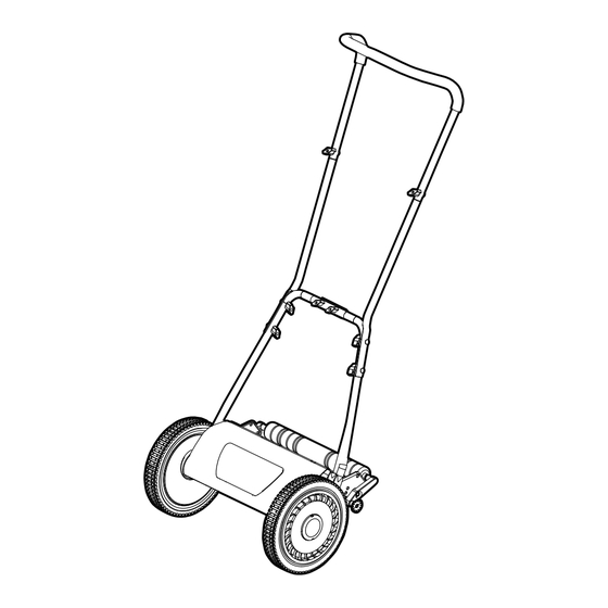
14" Reel Mower LMRM1401
Save this manual for future reference.
Advertisement

Subscribe to Our Youtube Channel
Related Manuals for LawnMaster LMRM1401


Summary of Contents for LawnMaster LMRM1401
- Page 1 Operator's Manual EN p. 2 14" Reel Mower LMRM1401 Save this manual for future reference. Read all safety rules and instructions carefully before operating this tool. Distributed By: Suzhou Cleva Electric Appliance Co., Ltd. NO.8 Ting Rong Street 215122 Suzhou - China...
- Page 2 13-14 TROUBLESHOOTING ® LAWNMASTER WARRANTY EXPLODED VIEW PARTS LIST 18-19 NOTES SPECIFICATIONS Reel Mower LMRM1401 Number of Blades 5 Hardened Steel Cutting Width 14'' (350 mm) Cutting Height Adjustment 4 positions: 1''-2'' (26-51 mm) Wheel Size 10'' (254 mm) Weight...
- Page 3 IMPORTANT SAFETY INSTRUCTIONS INTRODUCTION This product has many features for making its use more pleasant and enjoyable. Safety, performance, and dependability have been given top priority in the design of this product, making it easy to maintain and operate. WARNING READ AND UNDERSTAND ALL INSTRUCTIONS.
- Page 4 IMPORTANT SAFETY INSTRUCTIONS ■ Avoid operating the mower in a dangerous environment. Do not use the mower in damp or wet conditions or operate in the rain. Always be sure of your footing. A slip and fall can cause serious personal injury.
- Page 5 IMPORTANT SAFETY INSTRUCTIONS SAVE THESE INSTRUCTIONS Refer to them frequently and use them to instruct others who may use this appliance. If you loan someone this appliance, loan them these instructions also. SYMBOLS Some of the following symbols may be used on this product. Please study them and learn their meaning.
- Page 6 SYMBOLS The following signal words and meanings are intended to explain the levels of risk associated with this product. SYMBOL SIGNAL MEANING Indicates an imminently hazardous situation, which, if not DANGER avoided, will result in death or serious injury. Indicates a potentially hazardous situation, which, if not WARNING avoided, could result in death or serious injury.
- Page 7 KNOW YOUR REEL MOWER The safe use of this product requires an understanding of the information on the product and in this Operator’s Manual as well as a knowledge of the project you are attempting. Before use of this product, familiarize yourself with all operating features and safety rules. Components 1.
- Page 8 ASSEMBLY UNPACKING This product requires assembly. ■ Carefully remove the product and any accessories from the box. Make sure all items listed in the packing list are included. ■ Inspect the product carefully to make sure no breakage or damage occurred during shipping. ■...
- Page 9 ASSEMBLY ASSEMBLING THE HANDLES NOTE: Do not completely tighten bolts until assembly is complete. ■ Secure the upper handle to the middle handles with two bolts and two twist knobs (Fig. 1). ■ Connect the right lower handle with the left lower handle and secure with two bolts and two twist knobs (Fig.
- Page 10 ASSEMBLY ATTACHING THE HANDLE TO THE MOWER FRAME ■ Align holes at the lower end of each handle arm with posts extending from the mower frame side plates (Fig. 4). ■ Slide the lower end of the handle arms onto the posts. Hole Post Fig.
- Page 11 OPERATION WARNING Do not allow familiarity with this type of product to make you careless. Remember that a careless fraction of a second is sufficient to inflict serious injury. WARNING Do not use any attachments or accessories not recommended by the manufacturer of this product. The use of attachments or accessories not recommended can result in serious personal injury.
- Page 12 OPERATION ■ Your mower is not power-operated and requires continuous hand pushing during mowing. Use this mower only on lawn that has been grown on a smoothly graded ground surface. This mower is most effective on flat, even lawns. Mowing lawns with tall weeds may affect the overall mowing result. ■...
- Page 13 MAINTENANCE GENERAL MAINTENANCE ■ Always observe safety rules when performing any maintenance. ■ All adjustments should be checked at least once each season. ■ Periodically check all fasteners to ensure they are tight. ■ Regularly apply lubricant to mower’s cutting surfaces, cutting reel axle shaft and wheels. CLEANING AND STORING THE MOWER ■...
- Page 14 MAINTENANCE ■ Misalignment can occur, often caused by blades being too loose or too tight. This can cause an uneven cut or difficulty pushing the mower. ■ Each end of the cutting bar is adjusted separately. ■ To move the cutting bar closer to the blades, use a hex key to turn the adjustment screw clockwise. To move the cutting bar away from the blades, turn the adjustment screw counterclockwise (Fig.
- Page 15 TROUBLESHOOTING Suspected malfunctions are often due to causes that the user can fix themselves. Therefore, check the product using this section. In most cases the problem can be solved quickly. WARNING Only perform the steps described within these instructions! All further inspection, maintenance and repair work must be performed by an authorized service center or a similarly qualified specialist if you cannot solve the problem yourself! PROBLEM POSSIBLE CAUSE...
- Page 16 LAWNMASTER WARRANTY ® We take pride in producing a high quality, durable product. This Lawnmaster product carries a limited two (2) year warranty against defects in workmanship and materials from date of purchase under normal household use. If the product is to be used for commercial, industrial or rental use,a 30-day limited warranty will apply.
- Page 17 EXPLODED VIEW 24 23...
- Page 18 PARTS LIST Key Number Part Number Description Quantity Upper Handle Middle Handle Left Lower Handle Right Lower Handle Roller Shaft Roller Roller Shaft Sleeve 511002108 Height Adjustment Knob Assembly (L) Bolt Cutting Bar Pivot Rod Cutting Bar Assembly Blade Adjustment Nut Blade Adjustment Spring Blade Adjustment Bolt Supporting Plate (L)
- Page 19 PARTS LIST Key Number Part Number Description Quantity Wheel Shaft Supporting Plate (R) Washer 511002136 Height Adjustment Knob Assembly (R) 511002138 Twist Knob and Bolt Assembly (X8) Replacement parts highlighted in grey are available for after sales purchase. Replacement of repair or internal parts should only be done by a qualified service professional.
- Page 20 NOTES...
Need help?
Do you have a question about the LMRM1401 and is the answer not in the manual?
Questions and answers