Table of Contents
Advertisement
Quick Links
Operator's Manual
EN p. 2
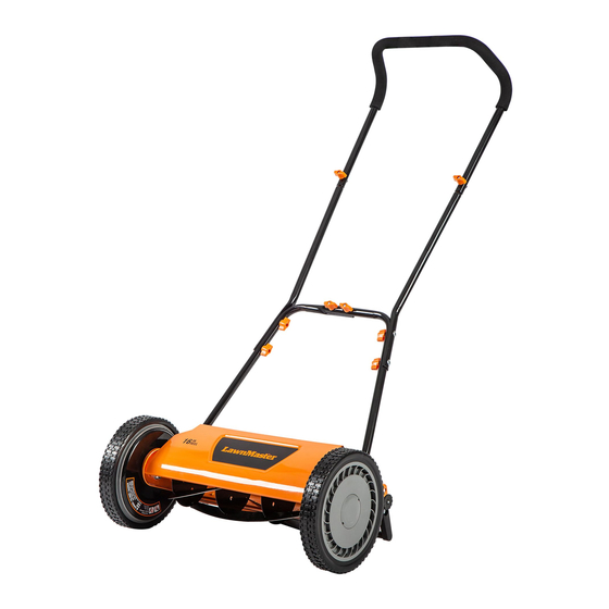
16" Reel Mower LMRM1602
Save this manual for future reference
Read all safety rules and instructions carefully before operating this tool.
Distributed By: Suzhou Cleva Electric Appliance Co., Ltd.
NO.8 Ting Rong Street 215122 Suzhou - China
NOTE: Collection Bag Sold Separately
Advertisement
Table of Contents

Subscribe to Our Youtube Channel
Related Manuals for LawnMaster LMRM1602


Summary of Contents for LawnMaster LMRM1602
- Page 1 Operator's Manual EN p. 2 16" Reel Mower LMRM1602 Save this manual for future reference NOTE: Collection Bag Sold Separately Read all safety rules and instructions carefully before operating this tool. Distributed By: Suzhou Cleva Electric Appliance Co., Ltd. NO.8 Ting Rong Street 215122 Suzhou - China...
-
Page 2: Table Of Contents
13-14 TROUBLESHOOTING ® LAWNMASTER WARRANTY EXPLODED VIEW PARTS LIST 18-19 NOTES SPECIFICATIONS Reel Mower LMRM1602 Number of Blades 5 Hardened Steel Cutting Width 16'' (400 mm) Cutting Height Adjustment 4 positions: 1''-2'' (26-51 mm) Wheel Size 10'' (254 mm) Weight... -
Page 3: Important Safety Instructions
IMPORTANT SAFETY INSTRUCTIONS INTRODUCTION This product has many features for making its use more pleasant and enjoyable. Safety, performance, and dependability have been given top priority in the design of this product making it easy to maintain and operate. WARNING READ AND UNDERSTAND ALL INSTRUCTIONS. - Page 4 IMPORTANT SAFETY INSTRUCTIONS conditions or operate in the rain. Always be sure of your footing. A slip and fall can cause serious personal injury. when the wheels turn the reel spins and can cut. Never place any part of the body in the blade area until you are sure the blade has stopped rotating. reel mower mechanisms.
-
Page 5: Symbols
IMPORTANT SAFETY INSTRUCTIONS SAVE THESE INSTRUCTIONS someone this appliance, loan them these instructions also. SYMBOLS Some of the following symbols may be used on this product. Please study them and learn their meaning. Proper interpretation of these symbols will allow you to operate the product better and safer. - Page 6 SYMBOLS associated with this product. SYMBOL SIGNAL MEANING Indicates an imminently hazardous situation, which, if not DANGER avoided, will result in death or serious injury. Indicates a potentially hazardous situation, which, if not WARNING avoided, could result in death or serious injury. Indicates a potentially hazardous situation, which, if not CAUTION avoided, may result in minor or moderate injury.
-
Page 7: Know Your Reel Mower
KNOW YOUR REEL MOWER this Operator’s Manual as well as a knowledge of the project you are attempting. Before use of this product, familiarize yourself with all operating features and safety rules. Components 1. Upper Handle 2. Twist Knob (X8) 3. -
Page 8: Assembly
ASSEMBLY UNPACKING packing list are included. the product. 8432). PACKING LIST (1) Upper Handle (2) Middle Handles (2) Lower Handles (8) Bolts (8) Twist Knobs (1) Reel Mower Body (with blades, wheels and height adjustment knobs installed) (1) Operator’s Manual WARNING If any parts are damaged or missing do not operate this product until the parts are replaced. - Page 9 ASSEMBLY ASSEMBLING THE HANDLES NOTE: Do not completely tighten bolts until assembly is complete. knobs (Fig. 2). four bolts and four twist knobs (Fig. 3). Fig. 1 Fig. 2 Fig. 3...
- Page 10 ASSEMBLY ATTACHING THE HANDLE TO THE MOWER FRAME plates (Fig. 4). Hole Post Fig. 4 WARNING Always keep hands clear of blades when attaching the handle to the frame. Not doing so can result in serious injury!
-
Page 11: Operation
OPERATION WARNING Do not allow familiarity with this type of product to make you careless. Remember that a careless WARNING Do not use any attachments or accessories not recommended by the manufacturer of this product. The use of attachments or accessories not recommended can result in serious personal injury. ADJUSTING THE CUTTING HEIGHT The cutting height can be adjusted to four positions, from 1'' to 2'' (26mm to 51mm). - Page 12 OPERATION mower only on lawn that has been grown on a smoothly graded ground surface. This mower is most or engine. cut. conventional rotary lawn mower. After mowing, readjust the blade to your preferred cutting height and mow the lawn a second time WARNING The operation of any lawn mower can result in debris being thrown into the eyes, which can damage your eyes severely.
-
Page 13: Maintenance
MAINTENANCE GENERAL MAINTENANCE CLEANING AND STORING THE MOWER damp cloth after each use. SHARPENING THE BLADES WARNING rotation can cause the blade reel to rotate. Periodically sharpen the blades as follows: bar. Refer to the Adjusting The Blades section in this manual. NOTE: To prevent surface rust to mower blades, dry blades after use and apply a thin coat of penetrating oil spray. - Page 14 MAINTENANCE To move the cutting bar away from the blades, turn the adjustment screw counterclockwise (Fig. 7). the blades and the cutting bar, and slowly turn the wheel by hand (Fig. 8). action. WARNING Do not over-tighten the adjustment screw, as this could damage the cutting bar. Tighten both screws Adjustment Screw Cutting Bar...
-
Page 15: Troubleshooting
TROUBLESHOOTING WARNING Only perform the steps described within these instructions! All further inspection, maintenance and repair work must be performed by an authorized service center PROBLEM POSSIBLE CAUSE SOLUTION Rough or uneven lawn. Check the mowing area. Mower cuts unevenly. Cutting height not set properly. -
Page 16: Lawnmaster ® Warranty
2. The unit, if it has not been operated and/or maintained in accordance with the owner's manual; 4. Routine maintenance items such as lubricants, blade sharpening; attachment are the responsibility of the purchaser. It is the purchaser's responsibility to pay transportation ® writing by LawnMaster SAVE YOUR RECEIPTS. THIS WARRANTY IS VOID WITHOUT THEM. -
Page 17: Exploded View
EXPLODED VIEW 24 23... -
Page 18: Parts List
PARTS LIST Key Number Part Number Description Quantity Upper Handle Middle Handle Left Lower Handle Right Lower Handle Roller Shaft Roller Roller Shaft Sleeve 511002108 Height Adjustment Knob Assembly (L) Bolt Cutting Bar Pivot Rod Cutting Bar Assembly Blade Adjustment Nut Blade Adjustment Spring Blade Adjustment Bolt Supporting Plate (L) - Page 19 PARTS LIST Key Number Part Number Description Quantity Wheel Shaft Supporting Plate (R) Washer 511002136 Height Adjustment Knob Assembly (R) 511002138 Twist Knob and Bolt Assembly (X8) Replacement parts highlighted in grey are available for after sales purchase. Replacement of repair or service dealer or Customer Service at 866-384-8432.
- Page 20 NOTES...
Need help?
Do you have a question about the LMRM1602 and is the answer not in the manual?
Questions and answers