Advertisement
Quick Links
Advertisement

Subscribe to Our Youtube Channel
Related Manuals for FläktGroup MultiMAXX HX


Summary of Contents for FläktGroup MultiMAXX HX
- Page 1 ® MultiMAXX OPERATION MANUAL...
- Page 2 Type Code MultiMAXX HX Type Code MultiMAXX Fig. 1-1 Unit code Fig. 1-2 Accessories Code 1 . U B . J X . X Model size Model size Model size 1 1 = Model size 1 Model size 2 2 = Model size 2...
- Page 3 Table of Contents MultiMAXX HX Table of Contents 1 Type Code ..................2 2 Table of Contents ................3 3 Safety and User Information ............5 3.1 Availability of the operation manual ..............5 3.2 Scope of application of the operation manual ..........5 3.3 Icons used ......................5...
- Page 4 Table of Contents MultiMAXX HX 9 Commissioning ................37 9.1 Pre-commissioning requirements ..............37 9.2 Vent the unit ....................38 9.3 Checking condensate drain ................38 9.4 Function check of frost protection (frost protection thermostat only with mixed-air units) .................... 38 9.5 Profile outlet ....................
- Page 5 Indicates work steps. Indicates process results. User instructions! Here you will find additional information on the use of the MultiMAXX HX air heater and its economical handling. Recycling! This symbol is used to highlight instructions on proper reuse of packaging material and disused assembly groups (separated according to recyclable materials).
- Page 6 Safety and User Information MultiMAXX HX Risk of personal injury! This section specifies procedures and precautions for preventing personal injury. Danger due to overhead loads! This icon warns about personal injury and damage caused by overhead loads and suspended heavy objects.
- Page 7 Proper use Units must be operated in accordance with EU 1253/2014. The MultiMAXX HX air heaters are designed for heating, cooling ventilating and filtering of indoor and outdoor air in industrial buildings of explosion risk area of zone 1. Units can be marked II 2G Ex h IIB T4/T3 Gb according to EN 14986 ed.2, EN ISO 80079-36, EN ISO 80079-37, EN IEC 60079-0 ed.5, EN 60079-7 ed.3 or II 2G Ex h...
- Page 8 14: Electrical installations for hazardous areas (except mines). Modifications and changes Do not attempt to modify, add components, or convert the MultiMAXX HX air heater in any way. Changes or modifications of unit heater will invalidate the CE conformity and render all warranty claims as null and void.
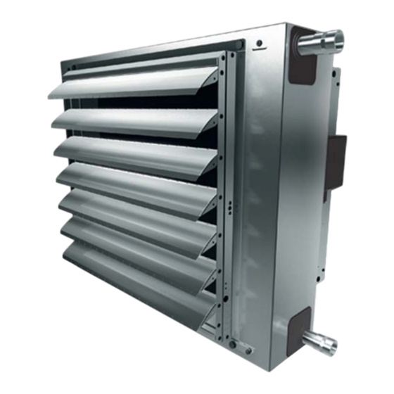
- Page 9 Technical Description MultiMAXX HX Technical Description Basic unit components Fig. 2-1: Basic unit components Pos. 1a: Fan with contact protection grille - II 2G Ex h IIB T4/T3 Gb Pos. 5: Unit casing Pos. 1b: Fan with contact protection grille - II 2G Ex h IIB+H2 T4/T3 Gb Pos.
- Page 10 MultiMAXX HX Unit setup The configuration of the MultiMAXX HX units comprises a fan, heat exchanger and casing performed in metal sheet or painted metal sheet. The discharge side is fitted with an optional discharge louvre. The axial fan is fitted on the rear side and is equipped with a contact protection grille as of EN ISO 13857.
- Page 11 (Tab.2-2). User instructions! All other important information about unit capacity, weights, connections and sound power is specified in the „Technical data - MultiMAXX HX" Max. allowed ambient temperature -20°C to +40°C Unit heater Max.
- Page 12 Technical Description MultiMAXX HX Unit dimensions and arrangement of heat exchanger connecting spigots 2.6.1 Medium technical function - heating (W), heating/cooling (V) Minimum space for mounting and maintenance Condensate tray with a free drainage 17mm (only with cooling units, medium func- tion V) Fig.
- Page 13 Technical Description MultiMAXX HX 2.6.2 Medium technical function S (heating - steam) Minimum space for mounting and maintenance Fig. 2-3: Dimension of unit heater and arrangement of heat exchanger connection fittings - only steam heating Table with unit dimensions for configuration: S –...
- Page 14 Technical Description MultiMAXX HX Heat exchanger connections Model size Rows Pipe connections Threaded pipe (external G 1" G 5/4" thread) Heat Exchanger C, A Smooth bore pipe external [mm] Threaded pipe (external G 1" G 1" G 5/4" G 5/4"...
- Page 15 Technical Description MultiMAXX HX Sound and electric data Sound power level (dB) A-rated sum level Max. Max. Speed Model Octave medium frequency (Hz) Sound Power Current Sound power size pressure* consumption consumption Spee dB(A) 1000 2000 4000 8000 dB(A) II 2G Ex h IIB T4/T3 Gb - Motor J (3 x 400 V)
- Page 16 Technical Description MultiMAXX HX 2.10 Air side accessories For MultiMAXX HX the following accessories can be supplied. Designation Order No. Design Mixed-air module, type 1* ZH#.20## Recirculating and outside air offset by 90° Mixed-air module, type 2* ZH#.21## Recirculating and outside air opposite at 180°...
- Page 17 Technical Description MultiMAXX HX 2.11 Commission Regulation (EU) 2016/2281 (Lot 30) November 2016 The values presented in the table Tab. 2-9 are provided to ensure the implementation of the EU Directive 2009/125/EG. This Directive sets the framework for the require-...
- Page 18 Shipping and storage MultiMAXX HX Shipping and storage Transport Observe the manufacturer’s instructions regarding shipping and storing the unit (see labels on the packing). User instructions! • When the unit heater is delivered and unpacked, check that the delivery is correct according to the despatch note, and also check for completeness and transit damage.
- Page 19 MultiMAXX HX Fig. 3-2: Transport Storage Protect the MultiMAXX HX unit from humidity and dirt. Store the unit on premises meet- ing ambient standards of class IE12 and in accordance with the requirements EN 60 721-3-1, Edition 2. User instructions! Allowable storage conditions: Air temperature: -25 °C to +40 °C...
- Page 20 Assembly MultiMAXX HX Assembly Load-bearing capacity of the installation site User instructions for setting up and mounting the unit! The assembly site must be vibration-free and suitable for permanently supporting the weight of the unit heater. If necessary, the approval of a structural engineer or architect must be received.
- Page 21 Assembly MultiMAXX HX Minimum distance from ceiling A (see Fig. 4-1) Provide minimum distance to ceiling to allow sufficient air circulation and ensure ade- quate access for maintenance. Model size Clearance A (mm) Unit spacing for ceiling mounting (see Fig. 4-2)
- Page 22 Assembly MultiMAXX HX Model size Clearance A (mm) 10 - 15 m 5 - 7 m 8 - 11 m 8 - 11 m Fig. 4-3: Distance between units with wall mounting FläktGroup DC-2009-0066- GB 2023-03/R9 • Subject to modification...
- Page 23 Assembly MultiMAXX HX Air throw Air throws are specified in the following table: Unit Size Air throw max. (m) HX11 HX12 HX13 HX14 HX21 HX22 HX23 HX24 Max. air throw HX31 HX32 HX33 HX34 HX41 10,8 HX42 10.2 HX43 HX44...
- Page 24 Assembly MultiMAXX HX User instructions! Units must be fitted level to the ceiling to allow access for air venting and bleeding of heat exchanger. Fixation points: unit heaters are secured in at least 4 fixation points. Use the screws of the transport safety device. When welding the heat exchanger connections, the heat exchanger casing must be protected.
- Page 25 Assembly MultiMAXX HX ZH#.31 ## ZH#.51 ## ZH#.29 ## ZH#.55#5 ZH#.21 ## ZH#.36 ## ZH#.25 ## Fig. 4-9: Wall mounting of the mixed-air unit with suspension "Modular" (ZH#.550#) With mixed-air units the flange for mounting accessories is fitted by the manufacturer;...
- Page 26 Medium connection MultiMAXX HX Medium connection Pipe connections User instructions! The supply and return piping should be run in such a way as to prevent mechanical stress and without placing a strain on the heat exchanger with sufficient clearance around the unit to allow for maintenance and servicing.
- Page 27 Medium connection MultiMAXX HX Connecting condensate drain To drain off condensate properly, field-provided condensate drain must be connected to the coil drip tray. (refer to Fig. 5 in the enclosed operation manual for louvers). • Insert a plastic hose on the relevant spigot of the drain pan and ensure proper sealing.
- Page 28 MultiMAXX HX Electrical connection Danger of electrical current! The electrical installation of MultiMAXX HX unit heaters must only be carried out by qualified electrical engineers in compliance with this operation manual and the cur- rent regulations: – VDE regulations, including safety regulations –...
- Page 29 (refer to Fig. on Page 35and Page 36). Operation with frequency convert- ers or control units with voltage reduction (e.g. transformer) is not possible. Terminal box/fan isolator The MultiMAXX HX unit heater is supplied with a plastic terminal box or fan switch. Earth terminal Fig. 6-1:...
- Page 30 Electrical connection MultiMAXX HX 6.3.1 1-speed operation with operating voltage 3 x 400 V (3 x 500 V) - unit with terminal box (K) – Power cable: 3 + PE = 4 connection wires – Electrically screened line: 2 K connecting wires...
- Page 31 Electrical connection MultiMAXX HX 6.3.3 1-speed operation with operating voltage 3 x 400 V (3 x 500 V) - unit with fan switch (S) – Power cable: 3 + PE = 4 connection wires – Electrically screened cable: 2 K connecting wires (T1, T2)
- Page 32 Electrical connection MultiMAXX HX Motor terminal diagram for 1-step three-phase standard motor M, N (3 x 400 V), O, P (3 x 500 V), unit designation II 2G Ex h IIB+H2 T4/T3 Gb – With PTC thermistor – Operating voltage: refer to unit identification plate 6.4.1 1-stage operation with operating voltage 3 x 400 V (3 x 500 V) - Device with terminal box (K)
- Page 33 Electrical connection MultiMAXX HX Fan isolator Fig. 6-8: Electrical connection - 1-stage operation - Unit with fan switch 6.4.4 1-stage operation with operating voltage 3 x 400 V (3 x 500 V) - Unit with fan switch (S) and control unit –...
- Page 34 MultiMAXX HX Frost protection monitoring of outdoor air unit and connecting damper actuator Monitoring of the heat exchanger is performed by MultiMAXX HX (II 2G c IIB(+H2) T3, T4) the frost protection thermostat. In conjunction with a 986960 or 986811 switchgear...
- Page 35 A maximum of 2 unit heaters (with consideration to motor full protection device) can be included in a unit group. 6.8.1 Installation example Unit group consisting of MultiMAXX HX air-recirculation units with control unit. Shut-off valve (refer to section 5.2 (by others))
- Page 36 (6) Shut-off valve: 3 wires (refer to Fig. 6-8) Control unit Type 986811.3 or 986960.3 (Type 986811T.51 or 986960T.51) Unit group consisting of MultiMAXX HX mixed air units with control unit Fig. 6-14: FläktGroup DC-2009-0066- GB 2023-03/R9 • Subject to modification...
- Page 37 Commissioning MultiMAXX HX Commissioning Danger of electrical current! Before performing any work on the unit, ensure that the unit is disconnected and powered down. Ensure that the unit is properly secured against subsequent switch- on at an appropriate point of the on-site power supply.
- Page 38 Commissioning MultiMAXX HX Vent the unit • Open all shut-off and control valves. • Use an air vent key to open an air vent screw by others. • Close the air vent screw again, only if heating/cooling medium is still pouring out.
- Page 39 Commissioning MultiMAXX HX Operation Activation and deactivation of the unit is performed using the speed selection switch or room thermostat or/and external remote switch. Operating instructions Ensure free air passage, air flow must be discharged without obstacles. Adjust the air jet so that there are no draughts in the occupied area! An optional fan switch fitted on the unit is only used to deactivate the fan.
- Page 40 Maintenance and Troubleshooting MultiMAXX HX Maintenance and Troubleshooting Maintenance User instructions! We recommend to conclude a maintenance contract with a service company. Danger of electrical current! Isolate all power supply connections of the GEA unit heater and ensure the power cannot be inadvertently energised.
- Page 41 Maintenance and Troubleshooting MultiMAXX HX Overview of regular maintenance intervals The following maintenance intervals must be observed within the specified periods. Maintenance intervals Components Checking air filter* (dirt, damage, odour) Checking air intake openings / grilles* Checking air discharge openings / grilles*...
- Page 42 Maintenance and Troubleshooting MultiMAXX HX Remove the heat exchanger before cleaning it. While removing heat exchanger the specified sequence must be adhered to (see Fig. 8-1). Compressed air or detergents and water must be used to clean a dirty heat exchanger. Replace and assemble all parts of the unit.
- Page 43 Maintenance and Troubleshooting MultiMAXX HX Before cooling season 8.4.1 Condensate tray cleaning Only for cooling units • Clean the drain pan • Check the drain connection or field-provided trap. Water must continuously drain through the drain connector, otherwise perform cleaning.
- Page 44 Maintenance and Troubleshooting MultiMAXX HX Troubleshooting Symptom Possible cause Action/remedy Fan does not work Unit not switched on Switch on unit Fan switch is switched on No mains voltage Check fuse/circuit breaker/power supply Indicator lights do not light up (technical personnel only)
- Page 45 Dismantling and Disposal MultiMAXX HX Dismantling and Disposal Environmental Damage! Dismantling and disposal of the MultiMAXX HX air treatment unit may only be car- ried out by appropriately qualified personnel! Dismantling Proceed as follows when dismantling the MultiMAXX HX unit...
- Page 46 Besides, the protective features must be checked as well. Inspection intervals depend on the operating conditions of the fan. The implementation of the inspection must be stated and confirmed in this installation manual. Air heater MultiMAXX HX (add type at 1st revision) Accessories ZH (add type at 1st revision) ............................
- Page 49 WWW.FLAKTGROUP .COM MULTIMAXX FläktGroup is the European market leader for smart and energy efficient Indoor Air and Critical Air solutions to support every application area. We offer our customers innovative technologies, high quality and outstanding performance supported by more than a century of accumulated industry experience. The widest product range in the market, and strong market presence in 65 countries worldwide, guarantee that we are always by your side, ready to deliver Excellence in Solutions.
Need help?
Do you have a question about the MultiMAXX HX and is the answer not in the manual?
Questions and answers