Table of Contents
Advertisement
Quick Links
Advertisement
Table of Contents

Subscribe to Our Youtube Channel
Related Manuals for FläktGroup MULTI FLAIR M 14 W0 Series


Summary of Contents for FläktGroup MULTI FLAIR M 14 W0 Series
- Page 1 MULTI FLAIR ® OPERATION MANUAL...
- Page 2 Multi Flair Product range FläktGroup DC-2008-0402-GB 2021-10/R10 • Subject to amendment...
- Page 3 Multi Flair Type code Multi Flair UNIT HEATER Controls package 1 . U G . B 3 . 0 1 . B Controller type Unit Type 2 = MATRIX 2000 = Comfort version (with designer grille) 3 = MATRIX 3000 = Standard (without de- signer grille) Controller package No.
-
Page 4: Table Of Contents
Multi Flair Content Safety and user instructions ......7 Operation manual scope ........7 Symbols used . - Page 5 Multi Flair Content Condensate drainage ........31 5.3.1 Condensate drain connection for units with a condensate pump 5.3.2 Condensate drain connection for units without a condensate pump.
- Page 6 Multi Flair Content 7.1.2 Before commissioning the following checks must be carried out: 63 7.1.3 Setting secondary air fins ....... 64 7.1.4 Following commissioning: .
-
Page 7: Safety And User Instructions
Safety and user instructions Multi Flair Safety and user instructions This is the original operation manual verified by the manufacturer. Multi Flair unit heaters are developed and manufactured using state-of-the-art techno- logy in accordance with the standards and regulations of the EU and CZ. Multi Flair unit heaters are safe and comply with high quality standards. -
Page 8: Safety Instructions: Warning Messages And Risk Symbols
Safety and user instructions Multi Flair Safety instructions: warning messages and risk symbols All information in this chapter is important and relevant to your safety. Therefore, not all information included in this chapter is highlighted using special warning symbols. Safety instructions in the following chapters of this operation manual are indicated by pictograms. -
Page 9: Safety At Work
Safety and user instructions Multi Flair Safety at work To ensure your own safety, comply with the following safety instructions: Risk of electrocution! Before commencing any work on the unit, disconnect the unit from the power supply and secure it against reconnection. (Check that the unit is not live, earth it and short- circuit conducting parts. -
Page 10: Improper Use
Safety and user instructions Multi Flair The following limit values apply for Cu/Al heat exchangers: Parameter Unit with Value Max. operating temperature °C Min. cooling temperature (when used with a MA- °C TRIX control system and valves) Max. operating pressure MPa (bar) 1.6 (16) Max. -
Page 11: Changes And Modifications
Safety and user instructions Multi Flair Changes and modifications No changes or modifications may be made to Multi Flair unit heaters or their compo- nents. Changes or modifications to Multi Flair units will invalidate the declaration of conformity and render all warranty claims null and void. Spare parts Only original spare parts are allowed to be used. -
Page 12: Technical Data
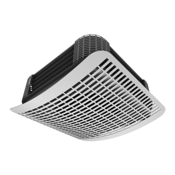
Technical data Multi Flair Technical data Unit components Pos. 1: Ceiling plate Pos. 2: Control electronics Pos. 3: Primary air supply connection Pos. 4: Corner guards (4 pieces) Pos. 5: Condensate pump – cooling (accessories) Pos. 6: 4-sided secondary air fin Pos. - Page 13 Technical data Multi Flair Some of the unit components from fig. 2-1 are described in detail below: Ceiling plate (pos. 1) Ceiling plate with primary air connection and air impact deflector Control electronics (pos. 2) – at 230 V with upstream resistor –...
-
Page 14: Operational Limits
Technical data Multi Flair Operational limits 2.2.1 Inlet medium temperature To prevent the temperature from falling below the dew point and the formation of con- densate on non-insulated parts of the unit in cooling mode, the specific minimum inlet temperature or evaporating temperature limits must not be exceeded. These depend on room temperature and relative humidity and are specified in the following diagram. -
Page 15: Dimensions
Technical data Multi Flair Dimensions 2.3.1 Basic unit Fig. 2-3: Basic unit dimensions Size Dimensions (mm) • b Ø D 900 • 800 301/355* 1000 • 900 310/360* 1100 • 985 Tab. 2-2: Basic unit dimensions; depending on structural dimensions H unit in “Standard”... -
Page 16: Electrical Data
Technical data Multi Flair 2.4.2 Electrical data Sound power level Sound pressure level* Max. power Size Speed levels Speed [rpm] Max. current [A] [dB(A)] [dB(A)] input [kW] AC-motor, 1 ~ 230 V, 1-speed 0.09 0.48 0.14 0.68 0.29 1.25 EC-motor, 1~230 V, continuous** min. -
Page 17: Condensate Pump
Technical data Multi Flair Condensate pump In cooling units, condensate may form which is collected in the condensate pan. The condensate pump drains condensate into drainage and sewage pipework located upstream. 2.5.1 Condensate drainage The condensate pump has a float switch with the following functions: –... - Page 18 Technical data Multi Flair Condensate pump capacity 1,40 Hose length 2.5 m 1,35 1,30 1,25 Hose length 5.0 m 1,20 1,15 1,10 1,05 1,00 0,95 0,90 0,85 Applies to: – Inner hose diameter: 6 mm 0,80 – Inner hose fitting diameter: 4.5 mm –...
-
Page 19: Ecodesign Directive Requirements Pursuant To Commission Regulation
Technical data Multi Flair Ecodesign Directive requirements pursuant to Commission Regulation (EU) 2016/ 2281 The values specified in tab. 2-6 are in accordance with the requirements of Commis- sion Regulation (EU) 2016/2281, implementing Directive 2009/125/EC of the Euro- pean Parliament and of the Council establishing a framework for the setting of ecodesign requirements for energy-related products, with regard to ecodesign require- ments for air heating products, cooling products, high temperature process chillers and fan coil units. -
Page 20: Transportation And Storage
Transportation and storage Multi Flair Transportation and storage Transportation safety Risk of injury from suspended loads! Standing underneath suspended loads may pose a risk to life. • Make sure that there are no people standing underneath suspended loads. Damage to the unit! Improper use may lead to damage to the Multi Flair unit heater. -
Page 21: Storage
Transportation and storage Multi Flair Storage The following must be observed during storage: – Multi Flair unit heaters may only be stored in their original packaging. – The storage site must conform to IE12 according to CSN EN 60721-3-1, must be protected from the elements, must be dry and dust-free and air humidity must be between 50 and 85% r.h. -
Page 22: Installation
Installation Multi Flair Installation Risk of electrocution! Before you start drilling, check that there are no electric or other lines at the drilling site. Personal injury! A risk of injury due to falling parts or sharp edges! During installation wear a hard hat, safety boots and gloves. -
Page 23: Installation Of The Unit
Installation Multi Flair Installation of the unit Before installing the unit, remove or uninstall the corner guards. 4.2.1 Removing corner guards Before installing the unit, remove or uninstall the corner guards. Removing corner guards: • Slide the corner guard upwards. •... - Page 24 Installation Multi Flair Attachment points Fig. 4-3: Drilling dimensions for ceiling-mounted Multi Flair unit heaters Size F (mm) Tab. 4-2: Attachment point dimensions Mounting kit 46D Mounting kit 46D (see fig. 4-4) consists of: – 4 hexagonal M8 bolts – 4 8 mm spring washers –...
-
Page 25: Installation To The Ceiling Using Threaded Rods
Installation Multi Flair 4.2.3 Installation to the ceiling using threaded rods For the dimensions of the ceiling plate and pipe connections see fig. 4-5. Ceiling plate Unit axis Primary supply connection View A Ø Top edge of the unit Mounting kit 46Z Pipe connections with female thread 3/4 Fig. -
Page 26: Primary Air Connection
Installation Multi Flair Attention! After the unit has been mounted and connections installed, the corner guards are to be fitted again. To do that carry out all of the above steps in reverse order. 4.2.4 Primary air connection (only for units with a primary air pipe connection fitting) Before mounting the unit to the ceiling or below a suspended ceiling the primary air connection fitting must be installed: •... -
Page 27: Designer Cover Installation (Only In Version M1)
Installation Multi Flair 4.2.5 Designer cover installation (only in version M1) Damage to the unit! In units with pipe connections from the side the designer cover must be installed on this side! • The angle bracket lugs and angle bracket should be screwed onto the bottom of the unit (holes are provided). -
Page 28: Hydraulic Connections
Hydraulic connections Multi Flair Hydraulic connections General Information In Multi Flair units without valves, or with valves fitted on site at a later date, the position of supply and return lines depends on coil connections performed by others and/or the valve used. -
Page 29: Installation Example: Pipe Connections From The Top
Hydraulic connections Multi Flair 5.2.1 Installation example: Pipe connections from the top Pos. 1: Supply line Pos. 2: Return line Pos. 3: Suspended ceiling Ø Fig. 5-1: Pipe connections from the top • Before the installation of the unit, lateral pipe connections must be properly sealed with the threaded plugs provided. -
Page 30: Protection Class / Water Volume / Weight / Sound Power Level
Hydraulic connections Multi Flair 5.2.3 Protection class / water volume / weight Size Protection IP20 IP20 IP20 Protection class Water volume: 1 row / 2 rows 1.2 / 2.2 1.5 / 2.6 1.7 / 3.2 Weight: Unit / enclosure 39.5 / 3.5 47.5 / 4.2 58.5 / 5.2 Tab. -
Page 31: Condensate Drainage
Hydraulic connections Multi Flair Condensate drain 5.3.1 Condensate drain connection for units with a condensate pump Condensate pump capacity is shown in the diagram (Fig. 2-5 on page 18). A short period of dry running (less than 5 minutes) will not impact the service life of the con- densate pump. -
Page 32: Condensate Drain Connection For Units Without A Condensate Pump
Hydraulic connections Multi Flair 5.3.2 Condensate drain connection for units without a condensate pump Pos. 1: Condensate drain hose, length: 1 m, internal diameter: 16 mm Fig. 5-4: Condensate drain connection provided by site contractors Attention! The connecting hose must be appropriately inclined. FläktGroup DC-2008-0402-GB 2021-10/R10 •... -
Page 33: Wiring Diagrams
Electrical connections Multi Flair Electrical connections Risk of electrocution! The electrical installation may only be carried out by persons qualified pursuant to Section 6 of Regulation CUBP and CBU No. 50/78 Coll. Attention! When connecting the unit observe operational safety regulations and generally recognized rules of engineering practice. - Page 34 Electrical connections Multi Flair Connections when using controllers, the MATRIX control system or control systems provided by site contractors The electrical connections of the unit are through the terminal block. This is located in the steel terminal box located in the corner of the unit (see Fig. 2-1). The wiring diagram is attached to the inside cover of the unit terminal box or is enclosed as a separate document.
- Page 35 Electrical connections Multi Flair Overview of MATRIX PCBs and control panels The unit’s terminal blocks, MATRIX PCBs and control panels are incorporated in the terminal box. The following overview shows the various connecting terminals and con- trol PCBs of the unit. To be able to make the necessary connections the PCB type always indicates the controller type it incorporates.
- Page 36 Electrical connections Multi Flair 6.3.2 Terminal block for a 230 V EC motor The unit’s terminal block for a 230 V EC motor is used for connecting to the 230 V mains power and the unit’s control system. Terminal block for a 230 V EC motor Size 1 Size 2 Size 3...
-
Page 37: Matrix 2001 And Matrix 3001 Control System
Electrical connections Multi Flair 6.3.3 MATRIX 2001 and MATRIX 3001 control system MATRIX MATRIX 2001 2002 3001 4001 2001 2002 3001 4001 – Power supply connection – Power supply connection – Valves (unless already connected at the factory) –... -
Page 38: Fan With Upstream Resistor
Electrical connections Multi Flair 6.3.4 Fan with upstream resistor In 3-speed 1 x 230 V AC motors speed is controlled using upstream resistors. This upstream resistor is used to set three default speed levels. Pos. 1: Upstream resistor on control panel Pos. -
Page 39: Controller Installation
Electrical connections Multi Flair Controller installation All IP20 controllers include an integrated room temperature sensor. The sensor can be used when the controller is located at an ideal place for temperature control in the room. All IP54 controllers are supplied with an external room temperature sensor. Attention! The installation site of the room temperature sensor is crucial for the precise control of room temperature. - Page 40 Electrical connections Multi Flair Electrical connection of controllers not included in the unit 6.5.1 Connection of terminal block for a 230 V AC motor – Connection can be made with a 1 to 5-speed controller installed outside the unit or controller 985.450. –...
- Page 41 Electrical connections Multi Flair 6.5.3 Connection of terminal block for a 230 V EC motor The electrical connection of a controller which is not part of the unit can be made for the various sizes of the unit with maximum control voltage rates as specified in the table below.
- Page 42 Electrical connections Multi Flair Fig. 6-10: Unit size 2, EC motor Fig. 6-11: Unit size 3, EC motor FläktGroup DC-2008-0402-GB 2021-10/R10 • Subject to amendment...
-
Page 43: Condensate Pump Connection
Electrical connections Multi Flair 6.5.4 Condensate pump connection Pos. 1: Power supply 230 V / 50 Hz / N / PE max. 16 A Pos. 2: Indication output (max. 230 V/2 A) max. 16 A 0,4 AT – K1 closes when the condensate level is too high. –... -
Page 44: Controller 985.450
Electrical connections Multi Flair 6.5.5 Connection of multiple unit heaters with a 230 V AC motor to a single 985.450 controller Multi Flair 1 Multi Flair 2 Multi Flair 3 The relevant thermostats (Heating or Cooling mode) are to be connected from the side. Intermediate terminal block 981.840 Power supply 230 V AC... - Page 45 Electrical connections Multi Flair 6.5.6 Connection of multiple unit heaters with a 230 V AC motor to a single 985.450 controller Multi Flair 1 Multi Flair 2 Multi Flair 3 The relevant thermostats (Heating or Cooling mode) are to be connected from the side. Intermediate terminal block 981.840 Power supply 230...
-
Page 46: Controller 985.420
Electrical connections Multi Flair 6.5.7 Connection of multiple unit heaters with a 230 V AC motor to a single 985.420 controller Multi Flair 1 Multi Flair 2 Multi Flair 3 The relevant thermostats (Heating or Cooling mode) are to be connected from Intermediate ter- the side. - Page 47 Electrical connections Multi Flair 6.5.8 Connection of multiple unit heaters with a 400 V AC motor to a single MC4U2AC.000 controller Multi Flair 1 Multi Flair 2 Multi Flair 3 The relevant thermostats (Heating or Cooling mode) are to be connected from Intermediate ter- the side.
- Page 48 Electrical connections Multi Flair 6.5.9 Connection of multiple unit heaters with a 230 V EC motor to a single MC4U1EC.000 controller Fig. 6-17: Connection of multiple unit heaters with a 230 V EC motor to a single MC4U1EC.000 controller – Up to 4 unit heaters can be connected via intermediate terminal block 981.101 to a single MC4U1EC.000 controller.
- Page 49 Electrical connections Multi Flair 6.5.10 Connection of multiple unit heaters with EC motors to a single 950EC1 controller Fig. 6-18: Connection of multiple unit heaters with a 230 V EC motor to a single 950EC1 controller – Up to 4 unit heaters can be connected via intermediate terminal block 981.101 to a single 950EC1 potentiometer.
-
Page 50: Electrical Connections With Matrix
Electrical connections Multi Flair Electrical connection with MATRIX 6.6.1 Power supply connection in units with a controller MATRIX 2001 2002 3001 4001 Pos. 1: Power supply 230 V AC / 50 Hz, overcurrent protection on site may not exceed B 10 A Pos. - Page 51 Electrical connections Multi Flair 6.6.2 Control cabling connection Attention! For connection use the following control cables: – In short lines and / or in environments without interference: multi-core control cable 0.5 mm shielded using aluminium coated plastic foil, e.g. J-Y(ST)Y 1x2x0.8 / 3x2x0.8 / 4x2x0.8.
- Page 52 Electrical connections Multi Flair MATRIX 2001 2002 3001 4001 Controller-to-unit heater connection with external valve control External room temperature sensor (optional) Only unit heaters with the MATRIX 2000 control system can be operated using the MATRIX OP21 controller. • Connect the control cables in accordance with the wiring diagram provided.
- Page 53 Electrical connections Multi Flair MATRIX 2001 2002 3001 4001 Connection between the first unit and an additional unit with external valve control Additional units may only be connected if they have MATRIX 2000 controls. • Connect the control cables in accordance with the wiring diagram provided.
- Page 54 Electrical connections Multi Flair 6.6.3 Bus line connection MATRIX 2001 2002 3001 4001 Controller-to-network participant connection To connect a MATRIX OP21 controller to a MATRIX.NET net- work 2-core bas cables must be used. • Connect the control cables in accordance with the wiring diagram provided.
- Page 55 Electrical connections Multi Flair 6.6.4 Connection of an outdoor air temperature sensor (optional) MATRIX 2001 2002 3001 4001 Pos. 1: Connecting cable (see the note on fig. 51 above) – Connecting the sensor in accordance with the wiring dia- gram provided.
- Page 56 Electrical connections Multi Flair 6.6.6 Connection of a room temperature sensor (optional) MATRIX 2001 2002 3001 4001 Pos. 1: Connecting cables (see the note on fig. 51 above) • Connect the room temperature sensor in accordance with the wiring diagram.
- Page 57 Electrical connections Multi Flair 6.6.9 Connection of valves 230 V MATRIX 2001 2002 3001 4001 Connection of an external valve actuator – A valve with a 230 V reversible actuator motor is necessary. – Depending on the unit’s equipment and the configuration of Valve open the control system, a valve for a 2-pipe, only Heating / only Cooling / Heating or Cooling system is used.
-
Page 58: Matrix.net Network And Connecting Shielding
Electrical connections Multi Flair MATRIX. Net network and connection of shielding This chapter provides information about MATRIX.Net and the proper way to set up a network. MATRIX.Net is a network which can be used to connect various FläktGroup control system components to each other via a data interface (network participants). Partici- pants can exchange the necessary control information through this data interface. - Page 59 Electrical connections Multi Flair MATRIX 3000 system group structure combined with a MATRIX 2000 system A group can be created with MATRIX 2000 and MATRIX 3000 systems. Fig. 6-39 The example shows a network consisting of a controller, MATRIX 2000 and MATRIX 3000 systems and various global modules.
- Page 60 Electrical connections Multi Flair Group structure with MATRIX 3000 and/or MATRIX 4000 systems A group can be created with MATRIX 3000 and MATRIX 4000 systems. fig. 6-40 The example shows a network consisting of a controller, MATRIX 3000 and MATRIX 4000 systems and various global modules.
-
Page 61: Matrix.net Network Structure
Electrical connections Multi Flair 6.7.2 MATRIX.Net network structure The network can consist of one or more (up to 16) groups. Global modules can be inte- grated into the network later. A MATRIX.Net system network configuration / topology must be created in a line structure – see “MATRIX.Net network topology” on page 62. An example of the maximum MATRIX.Net network structure is shown in Fig. -
Page 62: Matrix.net Network Topology
Electrical connections Multi Flair 6.7.3 MATRIX.Net network topology The MATRIX.Net can be built in a line structure or a line structure with a branch. All units with a MATRIX system have access to this data interface. To prevent reflections interfering with transmission the data interface must be termina- ted at each physical end. - Page 63 Electrical connections Multi Flair 6.7.5 Line structure with branches Fig. 6-43 shows a MATRIX.Net system configuration with a line structure with a branch. The example shows the connection of the controller via a branch in multiple groups. The maximum permitted branch length is 25 metres. Group 1 Group 2 Group X...
-
Page 64: Shielding / Earthing
Electrical connections Multi Flair 6.7.6 MATRIX.Net network configuration Data cable To create a MATRIX.Net network only data cables with twisted pair cores and shielding should be used (e.g. according to DIN 19245 T3). Attention! We recommend that the following data cable be used: e.g. -
Page 65: Commissioning
Commissioning Multi Flair Commissioning Risk of electrocution! Before performing any work on the unit, ensure that the unit is disconnected from the power supply. Ensure that the unit cannot be restarted by securing the on-site power supply. Risk of scalding! Before commencing work on air conditioning units: Before conducting any work on valves or connections, shut off the supply of heating medium. -
Page 66: Setting Secondary Air Fins
Commissioning Multi Flair 7.1.3 Setting secondary air fins • Hold the air fin profiles on the top right and bottom left sides simultaneously. • Move the fin profiles simultaneously in the required position. Fig. 7-1: Setting secondary air fins Attention! The discharge air direction must be set in such way as to prevent air draughts! 7.1.4 Following commissioning: •... -
Page 67: Condensate Pump Check (Only In Cooling)
Commissioning Multi Flair Condensate pump check (only in cooling) Attention! To prevent the transmission of structure-borne noise, suction and pressure lines must be routed in such a way that there is no contact between the base unit and pipework. Before commissioning make sure that –... -
Page 68: Terminating Resistors
Commissioning Multi Flair Terminating resistors MATRIX 2001 2002 3001 4001 The printed circuit boards of the MATRIX 2000 control system are not equipped with terminating resistors. The terminating resistors must be activated or deactivated on the control panel (con- troller) only if a MATRIX.Net network is to be established or additional modules such as input and output modules are to be connected. - Page 69 Commissioning Multi Flair MATRIX 2001 2002 3001 4001 The printed circuit boards of the MATRIX 3000 control system and MATRIX OP3X/44/ 5X are equipped with terminating resistors. Activation of terminating resistors at the beginning and end of the line (fig. 7-5): •...
- Page 70 Commissioning Multi Flair Address settings MATRIX 2001 2002 3001 4001 The printed circuit boards of the MATRIX 2000 control system are not equipped with terminating resistors. The appropriate group address must be assigned on the control panel. Single group (without networking multiple unit groups) •...
- Page 71 Commissioning Multi Flair MATRIX 2001 2002 3001 4001 The appropriate group address must be assigned on the control panel along with the units of a group. Single group (without networking multiple unit groups) • On the control panel, set the address to “0” (factory default setting). •...
-
Page 72: Starting The Unit
Commissioning Multi Flair Starting the unit Risk of electrocution! The terminal box is open. Tampering with the terminal box is prohibited! Before starting the unit, the terminal box must be properly closed (see “Electrical connections“ on page 33). • Start the power supply. •... -
Page 73: Data Connection Check
Commissioning Multi Flair Data connection check Risk of electrocution! Before correcting any data connection faults, power down the entire system. Ensure that the unit cannot be restarted by securing the on-site power supply. 7.7.1 Checking control cables MATRIX 2001 2002 3001 4001 ... -
Page 74: Checking Control Inputs And Outputs
Commissioning Multi Flair Checking control inputs and outputs MATRIX 3000 control systems have control inputs and outputs. When checking control inputs and outputs, pay attention to the factory settings. To see what functions your control system has, refer to the unit’s wiring diagram (enclosed in the terminal box). Configuration changes made on site (via MATRIX.PC servicing software) are not covered here. -
Page 75: Functions When Used With The Matrix Control System
Commissioning Multi Flair Functions when used with the MATRIX control system 7.9.1 Fan The fan is operated according to the control system configuration and the control mode selected on the unit’s controller. The following fan modes can be set: – Manual fan control –... -
Page 76: Condensate Pump
Commissioning Multi Flair 7.9.3 Condensate pump The condensate pump is used to drain the condensate which is formed in cooling units. The condensate pump starts when necessary based on humidity sensor readings. When the condensate limit level is exceeded, the fan stops, the valve in the cooling cir- cuit closes and the controller displays an error message. -
Page 77: Maintenance And Troubleshooting
Maintenance and troubleshooting Multi Flair Maintenance and troubleshooting Attention! Maintenance may only be carried out by qualified staff following the instructions in this user manual and the applicable regulations. Risk of injury from rotating mechanical parts! Risk of injury from rotating fan wheels! Before performing any work on the unit, ensure that the unit is disconnected from the power supply. -
Page 78: Regular Maintenance Interval Schedule
Maintenance and troubleshooting Multi Flair Regular maintenance interval schedule The following maintenance must be performed at the intervals specified in this sche- dule. Components Maintenance interval Filter inspection Heat exchanger cleaning * Inspection of hydraulic line threaded connections** Inspection of electrical connections Earthing inspection Bleeding the heat exchanger** Condensate drain inspection and condensate pan cleaning**... -
Page 79: Quarterly Maintenance
Maintenance and troubleshooting Multi Flair Quarterly maintenance 8.3.1 Filter cleaning / replacement When checking and replacing the filter according to fig. 8-1 proceed as follows: • Open the rotary catches and remove the filter cover panel. • Remove the filter cassette. •... -
Page 80: Annual Maintenance
Maintenance and troubleshooting Multi Flair Annual maintenance 8.4.1 Cleaning the heat exchanger • After removing the motor at the bottom of the unit, it is pos- sible to use that space to clean the inside of the heat exchanger including the suction area. Fig. -
Page 81: Heat Exchanger Bleed Check
Maintenance and troubleshooting Multi Flair 8.4.5 Heat exchanger bleed check • Bleed the heat exchanger as described in chapter 7.2. 8.4.6 Condensate pan and condensate pump cover cleaning • Clean the condensate pan. • Check and clean the main condensate pan drain point. This may include cleaning the condensate drain / condensate pump cover and the non-return valve. -
Page 82: Before Cooling Period
Maintenance and troubleshooting Multi Flair Before the cooling period 8.5.1 Condensate pump performance inspection • Check the condensate pump for proper function as described in chapter 7.3. Filter retrofitting Pos. 1: Filter cassette with filter mat Pos. 2: Transverse wire brackets (wire brackets face the unit side) Pos. -
Page 83: Operational Faults
Maintenance and troubleshooting Multi Flair Operational faults Exceptions to the normal operating conditions of the unit heaters indicate a malfunction and as such must be investigated by maintenance personnel. The following table should serve as a starting point for maintenance personnel regar- ding the possible causes of a malfunction and troubleshooting it. - Page 84 Maintenance and troubleshooting Multi Flair Fault Cause Troubleshooting The unit is not cooling / The fan has not been started Start the fan cooling insufficient Blocked air intake or exhaust point Unblock or clean the air duct Low air flow rate Increase fan speed Faulty / blocked fan Check or replace the faulty fan see page 81...
- Page 85 Maintenance and troubleshooting Multi Flair Fault Cause Troubleshooting Condensate pump The fan is not running The thermal contact (TC) of the fan motor and/ Check the fan motor thermal contact of the fan or alarm contact of the condensate pump are motor (connection) Replace the electronics and Red controller LED: active/tripped Fan stopped...
-
Page 86: Ec Declaration Of Conformity
Multi Flair EC DECLARATION OF CONFORMITY pursuant to Directive 2006/42/EC of the European Parliament and of the Council (government regulation No. 176/2008 Coll.) (original EC Declaration of Conformity) 2021/068/5AB24236 Manufacturer: FläktGroup Czech Republic a.s., Slovanska 781, 463 12 Liberec XXV - Vesec, Czech Republic, IC (Company ID): 46708375 Entity authorized to compile technical documentation: FläktGroup Czech Republic a.s., Slovanska 781, 463 12 Liberec XXV - Vesec, Czech Republic, IC (Company ID):... - Page 87 Notes Multi Flair FläktGroup DC-2008-0402-GB 2021-10/R10 • Subject to amendment...
- Page 88 WWW.FLAKTGROUP.COM MULTI FLAIR FläktGroup is the European market leader for energy-efficient solutions for air handling applications suitable for every application area according to your requirements. We offer our customers innovative technologies, high quality and outstanding performance supported by more than a century of accumulated industry experience. Our wide product range and market presence in 65 countries worldwide, guarantee that we are always by your side, ready to deliver excellent solutions.
Need help?
Do you have a question about the MULTI FLAIR M 14 W0 Series and is the answer not in the manual?
Questions and answers