Table of Contents
Advertisement
Advertisement
Table of Contents

Related Manuals for FläktGroup HYPOWER-GEKO


Summary of Contents for FläktGroup HYPOWER-GEKO
- Page 1 ® HYPOWER-GEKO OPERATION MANUAL...
- Page 2 HyPower-Geko Product range FläktGroup FläktGroup DC-2014-0022-GB 2018-05/R5 • Subject to modifications...
- Page 3 HyPower-Geko Unit Type Code Unit type code MATRIX Controller Valve code 1 . U 3 . F 3 . 0 1 . B H . R 6 . 1 Cooling/heating circuit Heating circuit Model size 1 = Model size 1...
-
Page 4: Table Of Contents
Table of Contents HyPower-Geko 1 Safety and User Instructions ............6 1.1 Availability of the operation manual ........6 1.2 Symbols used ................ 6 1.3 Safety instructions: warning and danger symbols ....6 1.4 Safety-conscious work procedures ........7 1.5 Personnel selection and qualification ........8 1.6 Proper use ................ - Page 5 HyPower-Geko Table of Contents 6.5 Overview of the FläktGroup MATRIX control electronics ..61 6.6 Mounting control panel ............62 6.7 Electrical connection with MATRIX ........63 6.8 Network and shielding connection MATRIX.Net ....70 6.9 Electrical connection of FläktGroup miniature switches/relay PCB for units with AC fans ............76 6.10 Electrical connection for AC fan with FläktGroup miniature...
-
Page 6: Safety And User Instructions
Safety and User Instructions HyPower-Geko Safety and User Instructions This is an original operation manual verified by the manufacturer. HyPower fan coil units are developed and manufactured in accordance with the state- of-the-art technological standards, established technical safety codes and EC Direc- tive on Machinery. -
Page 7: Safety-Conscious Work Procedures
HyPower-Geko Safety and User Instructions Risk of personal injury! This symbol indicates (different from the above-mentioned danger types) a hazard- ous location with a risk of personal injury including death and material damage. Danger due to overhead loads! This symbol indicates a hazardous suspended load with a risk of personal injury including death and material damage. -
Page 8: Personnel Selection And Qualification
Safety and User Instructions HyPower-Geko Risk of personal injury! Always wear protective gloves when shipping or installing the unit to prevent injury caused by sharp edges. The following accident prevention regulations apply (VBG1, BGV A2 (previously: VBG4), VBG7w, VBG9a) and generally recognized codes for machinery and principles of engineering, particularly DIN VDE 0100, DIN VDE 0105. -
Page 9: Improper Use
Geko units, all local safety regulations and codes as well as generally established tech- nical practices must be followed. Modifications and changes No changes, add-ons or modifications may be performed on the HyPower-Geko air treatment unit or its components. Changes or modifications of the Flex-Geko unit will invalidate the CE conformity and render all warranty claims null and void. -
Page 10: Technical Description
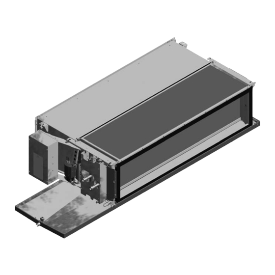
Technical Description HyPower-Geko Technical Description Basic unit components Fig. 2-1: Basic unit components Pos. 1: Basic casing (incl. assembly mountings) Pos. 8: Condensate pump (optional) Pos. 2: Fan chamber (optional)* Pos. 9: Service panel Pos. 3: Heat exchanger: Cu/Al Pos. 10: Cover for heat exchanger and condensate drain Pos. - Page 11 For heating-only units bottom basic casing cover is mounted instead of condensate tray Pos. 6. Condensate tray (optional) (pos. 6) In the HyPower-Geko, the condensate tray is for the collection of the condensation water forming at the heat exchanger. Auxiliary condensate tray (only for unit type U - GH##.U###.#####) (pos. 7) Additional condensate tray for the collection of condensation water from the control valves and shut-off instruments.
-
Page 12: Material Specification
Technical Description HyPower-Geko Material specification Unit part Material Fan chamber (optional) Galvanized sheet steel (optionally: insulation made of mineral wool laminated with glass fiber) Basic casing (including assembly mountings) Galvanized steel sheet, insulation PE Heat Exchanger Copper/aluminium (copper/copper, copper/alodine) AC and EC-Motor... - Page 13 HyPower-Geko Technical Description 2.3.2 External air side resistance User instructions! The on-site external air-side resistance may not exceed the values 200 Pa at 300 m3/h for size 1, 500 m3/h for size 2, 700 m3/h for size 3 and 1000 m3/h for size 4.
- Page 14 Technical Description HyPower-Geko 2.3.4 Valves with modulating actuators Valves with modulating Values actuator 230 V/24 V 230 V 24 V Max. operating pressure/inlet temperature 1.6 MPa (16 bar) / 110 °C Max. allowed ambient temperature 60 °C Operating voltage 230 V AC...
-
Page 15: Dimensions
HyPower-Geko Technical Description Dimensions 2.4.1 Basic unit Fig. 2-3: Dimensions for unit type U without fan chamber (A) (not certified as of VDI 6022) - GH##.U###.###A0 Model size b [mm] 1170 1590 Tab. 2-8: Width of basic unit, depending on unit size Fig. - Page 16 Technical Description HyPower-Geko Fig. 2-5: Dimensions for unit type H with fan chamber (B, C) - GH##.H###.###B(C)# Model size b [mm] 1170 1590 Tab. 2-10: Widths dependent on unit size 2.4.2 Air side accessories Fig. 2-6: Dimensions of intake and discharge plenum(ZGH.#A031 / ZGH.#A042)
- Page 17 HyPower-Geko Technical Description Fig. 2-7: Dimensions of intake and discharge plenum Fig. 2-10: Dimensions of air-intake and air-discharge sound (ZGH.#A111 / ZGH.#A112) absorber fittings (ZGH.#A211 / ZGH.#A212) Fig. 2-8: Dimensions air intake grille (intervention protection) Fig. 2-11: Dimensions of air discharge transition piece (ZGH.#A511)
-
Page 18: Unit Data
Technical Description HyPower-Geko Unit data 2.5.1 Unit weight and water charge of heat exchanger Model size Weight1) [kg] Water charge[l] 2-pipe 4-pipe Cooling circuit Heating circuit VK A VK B VK C CS 1 CS 2 CS 3 CS 1... -
Page 19: Condensate Pump
HyPower-Geko Technical Description 2.5.4 Electrical data for fans Current consumption [A]* Power consumption [W]* Model size Fan type Min. / Max. Min. / Max. VK A VK B VK C VK A VK B VK C 0.64 / 0.98 0.57 / 0.75 0.56 / 0.69... - Page 20 Technical Description HyPower-Geko 2.6.2 Technical data and capacity of condensate pump The max. delivery head of the pump is 8 m, the maximum volume flow is 14 l/h. In the fig. 2-14 the power of the pump is specified in l/h relative to the delivery head.
-
Page 21: Air Side Accessories
HyPower-Geko Technical Description Air side accessories The following accessories can be supplied for the HyPower-Geko fan coil unit: Designation Order No. Design Flexible connection ZGH.#A112 discharge Fire classification B1 ZGH.#A111 intake Air intake box with round connec- ZGH.#A031 Air intake plenum with round connectors DN 250, galvanized... -
Page 22: Commission Regulation (Eu) 2016/2281
Technical Description HyPower-Geko Commission Regulation (EU) 2016/2281 (Lot 30) November 2016 The values presented in the table Tab. 2-20 are provided to ensure the implementation of the EU Directive 2009/125/EG. This Directive sets the framework for the require- ments to the environmentally-friendly design of energy-related products such as air heaters, air coolers, units for air cooling in industrial processes with high operating tem- perature and fan coil units. - Page 23 HyPower-Geko Technical Description Units rated,c rated,c rated,c rated,h elec [kW] [kW] [kW] [kW] [kW] [dB(A)] 0,185 41,0 GH31.#W0(0W, WC)#. 0,303 1555 57,0 11,8 0,396 2565 67,0 0,185 42,0 0,298 1540 57,0 GH31.#WW#. 12,3 10,8 12,1 0,383 2455 66,0 0,027 46,0...
-
Page 24: Shipping And Storage
• Always wear protective gloves to prevent injury caused by sharp edges. • To prevent injury ensure that at least two people carry the HyPower-Geko. • When delivering on pallets, use only lifting gear and transport vehicles with suf- ficient load-bearing capacity. -
Page 25: Temporary Storage
HyPower-Geko Shipping and storage Horizontal transport The HyPower-Geko must only be transported and lifted on both sides of bottom edges (refer to fig. 3-1). Fig. 3-1: Transport Temporary storage When storing the unit for a temporary period, the following aspects must be consid- ered: –... -
Page 26: Mounting
Mounting HyPower-Geko Mounting Danger of electrical current! Before drilling, ensure that the drilling area is free from electrical cables and pipes. Risk of personal injury! Injury may be caused by falling parts and sharp edges! Wear a helmet, safety boots and protective gloves when installing the unit. Ceiling installations should always be performed by two persons. -
Page 27: Recommended Service Opening For Maintenance Work On The Basic Unit
HyPower-Geko Mounting Recommended service opening for maintenance work on the basic unit 4.2.1 Unit type U (GH##.U###.#####) In order to carry out all necessary service and maintenance work on the basic unit it is recommended that a service opening with minimum dimensions of B x 1150 mm (B x 1040 mm)* is provided (see fig. - Page 28 Mounting HyPower-Geko 4.2.2 Unit type H (GH##.H###.#####) In order to carry out all necessary service and maintenance work on the basic unit it is recommended that a service opening with minimum dimensions of B x 1150 mm (B x 1040 mm)* is provided (see fig. 4-2 ) Fig.
-
Page 29: Pre-Installation Work
HyPower-Geko Mounting Pre-installation work Depending on the connection side, the pipes can be connected from the left or from the right. The following installation clearances must be observed: Position No., REASON Installation refer to fig. 4-3 clearance [mm] for proper inflow of the air from... -
Page 30: Unit Mounting
Mounting HyPower-Geko Unit mounting 4.4.1 Installation with various fixing materials To fasten the units, assembly mountings with 2 holes are provided (1 on each side, see fig. 4-6, Pos. 1). Appropriate fixing accessories are needed depending on the mounting variant (refer to fig. 4-5). - Page 31 Ensure connection possibility for the mounting brackets (examples in fig. 4-5). • Use bolts/screws to fix the HyPower-Geko unit. • Use a spirit level to exactly align the HyPower-Geko in longitudinal and lateral di- rection (refer to fig. 4-6). • Tighten the fixing bolts.
- Page 32 Mounting HyPower-Geko 4.4.2 Mounting with suspension rail (accessory) Suspension rails are available for easy and quick installation as an accessory. Depending on the type and number of mounted accessory modules, three different rail lengths are available. The fig. 4-7 demonstrates possible module combinations.
- Page 33 HyPower-Geko Mounting Pos. 1: Threaded rod M8 Pos. 2: Assembly track Pos. 3: Track adapter Pos. 4: Screw M8x25, washer, nut Pos. 5: Assembly mounting of the unit/accessories • Use the fixing material (see fig. 4-8, Pos. 4) to fasten the rail adapt- ers (see fig.
- Page 34 • Hang the HyPower-Geko with rail adapters (see fig. 4-8) in the suspension track. • Lift the opposite side of the HyPower-Geko unit so that the threaded rods go through the holes of the assembly mountings. • Connect the HyPower-Geko using supplied fixing material.
- Page 35 HyPower-Geko Mounting 4.4.3 Assembly discharge transition piece (ZGH.#A912) User instructions! For the assembly of discharge side accessories (discharge sound attenuator, dis- charge plenum, flexible canvas discharge connection or on-site ducts) on the basic unit, the discharge transition piece (Order No.: ZGH.#A912, where the # sign indi- cates the model size of the unit) is absolutely required.
- Page 36 Mounting HyPower-Geko 4.4.4 Mounting flexible canvas connection User instructions! The flexible canvas connection is delivered separately with the enclosed adhesive tape provided for the duct seal between the flange of the flexible supports and the unit with fan chamber or sound attenuator, or discharge transition piece.
- Page 37 HyPower-Geko Mounting 4.4.6 Assembly of the intake/discharge sound attenuator User instructions! The intake/discharge sound attenuator is delivered with separately enclosed adhe- sive tape provided for the duct seal between the flange of the sound attenuator and the unit with fan section or the discharge-transition piece.
- Page 38 Mounting HyPower-Geko 4.4.7 Installation intake/discharge plenum and seal cap for round connector DN250 User instructions! The intake/discharge plenum with round connector DN250 is delivered with sepa- rately enclosed adhesive tape provided for the seal between the flange of the box and the unit with fan section or the discharge-transition piece, or intake/discharge- sound attenuator or flexible canvas connection.
- Page 39 HyPower-Geko Mounting 4.4.8 Mounting filter chamber with top/side removal (ZGH.#A411 / ZGH.#A421) Notice! The filter chambers with top/side removal (ZGH.#A411 / ZGH.#A4212) are supplied with a separately enclosed insulation tape. This tape is used as a sealing between the connection of the filter chamber and the fan chamber of unit.
- Page 40 Mounting HyPower-Geko 4.4.9 Installation of condensate tray User instructions! This notice only concerns the unit in cooling operation. The condensate tray is always supplied separately and is to be installed before unit assembly. The condensate drain outlet of the condensate tray must always be on the heat exchanger connection side! Pos.
-
Page 41: Hydraulic Connection
DANGER OF SCALDING BY ESCAPING HEATING MEDIUM! Before the on-site piping and hydraulic connections of the Hypower-Geko are set up, the heating/cooling medium must be shut off and secured against inadvertent opening. - Page 42 Hydraulic Connection HyPower-Geko With a 2-way valve, control is carried out by throttling the medium supply (see fig. 5-2). Fig. 5-2: Motor actuated 2-way valve Valves with thermoelectric actuator On/off operation (open/close) is possible with these valves. If 3-way valves are fitted by the manufacturer, control is performed via a distributor circuit (refer to fig.
-
Page 43: Heating And Cooling Connections For Units Without Valves Or With On-Site Valves Provided By Others
HyPower-Geko Hydraulic Connection Ball valve The ball valve is used to limit or shut off the medium flow (refer to fig. 5-6). Ball valve Fig. 5-6: Heating and cooling connections for units without valves or with on-site valves provided by others... - Page 44 Hydraulic Connection HyPower-Geko Pos. 1: Water inlet (internal screw thread, see Tab. 5- Pos. 2: Return line (internal screw thread, see Tab. 5-1) Fig. 5-7: Heat exchanger connections 2-pipe system, left connection Pos. 1: Water inlet (internal screw thread, see Tab. 5- Pos.
- Page 45 HyPower-Geko Hydraulic Connection 5.3.4 Medium connection in a 4-pipe system User instructions! When making a medium connection to the unit, always ensure the correct connec- tion to the input and output of the heat exchanger! Exchanging the connections can lead to loss of efficiency! (see fig. 5-9 and fig. 5-10) The connection fittings of the heat exchanger always have an inner thread.
-
Page 46: Heating And Cooling Water Connections For Units With Factory-Mounted Valves
Hydraulic Connection HyPower-Geko Heating and cooling water connections for units with factory-mounted valves 5.4.1 Mounting connections • At the beginning of the fitting procedure, remove caps on the water inlet and outlet pipes. • Fit the connections while ensuring they are free of mechanical stress. - Page 47 HyPower-Geko Hydraulic Connection 5.4.2 Medium connection in a 2-pipe system 2-way valve Pos. 1: Supply line Pos. 2: Valve actuator motor Pos. 3: Shut-off valve/ball valve (optional) Pos. 4: Return line Fig. 5-11: Piping connections of 2-pipe system, 2-way valve, left connection Pos.
- Page 48 Hydraulic Connection HyPower-Geko 3-way valve Pos. 1: Supply line Pos. 2: Valve actuator motor Pos. 3: Shut-off valve/ball valve (optional) Pos. 4: Return line Fig. 5-13: Piping connections of 2-pipe system, 3-way valve, left connection Pos. 1: Supply line Pos. 2: Valve actuator motor Pos.
- Page 49 HyPower-Geko Hydraulic Connection 5.4.3 Medium connection in a 4-pipe system 2-way valve Pos. 1: Supply line cooling Pos. 2: Valve actuator motor cooling Pos. 3: Shut-off valve/ball valve cooling (optional) Pos. 4: Shut-off valve/ball valve heating (optional) Pos. 5: Return line cooling Pos.
- Page 50 Hydraulic Connection HyPower-Geko 3-way valve Pos. 1: Supply line cooling Pos. 2: Valve actuator motor cooling Pos. 3: Shut-off valve/ball valve cooling (optional) Pos. 4: Shut-off valve/ball valve heating (optional) Pos. 5: Return line cooling Pos. 6: Supply line heating Pos.
-
Page 51: Connecting Condensate Drain
HyPower-Geko Hydraulic Connection Connecting condensate drain To drain off condensate properly, the condensate drain provided on-site must be con- nected to the coil drip tray. • Insert a plastic hose or a copper pipe on the provided connector of the drain pan and seal it, (refer to fig. -
Page 52: Connecting Condensate Pump
Hydraulic Connection HyPower-Geko Connecting condensate pump Pos. 1: Condensate tray Pos. 2: Plastic-end piece of the suction hose of the condensate pump Pos. 3: Inlet hose Pos. 4: Condensate pump Pos. 5: Pressure hose (1.5 m long) Pos. 6: Fill level sensor Pos. - Page 53 HyPower-Geko Hydraulic Connection NOTICE! When laying out the pressure hose, ensure that it is not bent or folded. Insulate the hose against all surfaces with which it could come into contact to prevent the transmission of structure-borne noise. Actual discharge volume of condensate pump in [l/h]...
-
Page 54: Electrical Connection
Miniature switch C 6 A Tab. 6-1: Fusing Terminal box or electric switch cabinet Depending on the model variant, the HyPower-Geko is delivered with a – Terminal boxand metal sheet electrical control box Terminal box Metal-sheet electric switch cabinet Fig. 6-1:... -
Page 55: Fan Speed
HyPower-Geko Electrical connection Depending on the model, the metal sheet electrical switch cabinet contains: – one terminal strip and other electrical parts (if required) – a control/power electronics (MATRIX 2001/3001/4001) Fan speed 6.3.1 Fan with AC motor (3/5-speed motor) The fan motor is fitted with five controllable speeds. According to the customer require- ments the manufacturer can supply 3 or 5 speed stages (see unit-specific wiring dia- gram Tab. -
Page 56: Connection With Controls Provided By Others
Connect only in accordance with the unit-specific wiring diagram. 6.4.1 Connecting HyPower-Geko with AC motors If a HyPower-Geko is fitted with control by others, the customer can either select a ter- minal strip or FG-relay PCB to be supplied with the unit. - Page 57 Only terminals for wiring control and steering system are presented. Depending on the unit configuration, the number of terminals varies. • Connect multiple HyPower-Geko units in accordance with the wiring diagram. Fig. 6-3: Connection termial block/relay PCB User instructions! Before commencing connections, check that the order code of the unit's electrical equipment matches the wiring diagram.
- Page 58 Connecting multiple HyPower-Geko units without FG-relay PCB User instructions! Multiple HyPower-Geko units without a FG-relay circuit board can be equipped and combined with an external controller according to Fig. 6-4. Cut-off relays must be provided by others (K1 - K3).
- Page 59 HyPower-Geko Electrical connection User instructions! Before commencing connections, check that the order code of the unit's electrical equipment matches the wiring diagram. Model size Number of EC motors Fan type S + D D + D Tab. 6-5: Number of EC motors (S...single, D...double) If a unit is fitted with one motor, an alarm signal is conducted to the terminals 11.1.
- Page 60 *) =The connections highlighted in light gray were executed at the factory. This view provides a better visualization of the switches. = Number of line wires: e.g: 5 x 1.5 mm² NYM • Connect multiple HyPower-Geko units in accordance with the wiring diagram. FläktGroup DC-2014-0022-GB 2018-05/R5 • Subject to modifications...
-
Page 61: Overview Of The Fläktgroup Matrix Control Electronics
HyPower-Geko Electrical connection Overview of the FläktGroup MATRIX control electronics MATRIX control electronics are built into the electric switch cabinet. The following table illustrates different controller circuit boards. In order to enable you to make the nec- essary connections, the following PCB layouts illustrate the controller type installed in each case. -
Page 62: Mounting Control Panel
Electrical connection HyPower-Geko Mounting control panel All IP20 control panels have an integrated room-temperature sensor. The latter can be used when the control panel is mounted at an optimum indoor location for regulating temperature. All IP54 control panels are supplied with a separate external room tem- perature sensor. -
Page 63: Electrical Connection With Matrix
HyPower-Geko Electrical connection Electrical connection with MATRIX 6.7.1 Connecting mains supply voltage for controller MATRIX 2001 3001 4001 4001+IO Pos. 1: Power supply 230 V AC / 50 Hz, on-site fusing by others max. B 10 A Pos. 2: Connection to first unit Pos. - Page 64 Electrical connection HyPower-Geko MATRIX 2001 3001 4001 4001+IO Connecting control panel – unit - other slave units Control panel MATRIX OP21 can only be connected to units equipped with MATRIX 2000.A maximum of 16 units can be connected to OP21.
- Page 65 HyPower-Geko Electrical connection MATRIX 2001 3001 4001 4001+IO Connecting master unit MATRIX 3000 – slave units MATRIX 2000 Units with MATRIX 3000 can be operated with units fitted with MATRIX 2000. • Connect control cables in accordance with the wiring diagram.
- Page 66 Electrical connection HyPower-Geko MATRIX 2001 3001 4001 4001+IO Control panel connection – air-handling unit Control panels MATRIX OP3x/44/5x can only be operated with units fitted with MATRIX 3000 controller electronics. • Connect the control cables in accordance with the wiring diagram.
- Page 67 HyPower-Geko Electrical connection Pos. 1: Connecting cable (refer to notice on Seite 63) • Connect the outdoor sensor according to wiring diagram. Fig. 6-16: Connecting outdoor sensor 6.7.5 Connecting the inlet sensor (option) MATRIX 2001 3001 4001 4001+IO Pos. 1: Connecting cable (refer to notice on Seite 63) •...
- Page 68 Electrical connection HyPower-Geko MATRIX 2001 3001 4001 4001+IO Pos. 1: Con- necting cable (refer to notice on Seite 63) • Connect the room or return-air sensor according to the wiring diagram. Fig. 6-20: Connecting room sensor/return-air sensor 6.7.7 Connecting supply-air sensor (for subsequent retrofitting)
- Page 69 HyPower-Geko Electrical connection 6.7.9 Connecting status and fault signal MATRIX 2001 3001 4001 4001+IO It is possible to tap the status and alarm messages on the con- trollers using floating contacts. The contact load at 230 V AC amounts to a maximum of 4 A ohmic / 2 A inductive.
-
Page 70: Network And Shielding Connection Matrix.net
Electrical connection HyPower-Geko Network and shielding connection MATRIX.Net This section contains information about the MATRIX.Net and the correct network setup. MATRIX.Net is a network for connecting various components of the FläktGroup control system (network users) in one data bus. The bus enables the exchange of all information required for control and regulation between the users. - Page 71 HyPower-Geko Electrical connection Group structure of the MATRIX 3000 system in combination with the MATRIX 2000 system A group may be formed using the MATRIX 2000 and MATRIX 3000 systems. The fig. 6-27 shows an example of a network consisting of a control panel, MATRIX 2000 system, MATRIX 3000 system and various global modules.
- Page 72 Electrical connection HyPower-Geko Group structure with MATRIX 3000 and/or MATRIX 4000 system A group may be formed using the MATRIX 3000 and MATRIX 4000 systems. The fig. 6-28 shows an example of a network consisting of a control panel, MATRIX 3000 system, MATRIX 4000 system and various global modules.
- Page 73 HyPower-Geko Electrical connection 6.8.2 Network structure MATRIX.Net A network can consist of one or several (up to 16) groups. Global modules can also be integrated into the network. The network structure/network topology of MATRIX.Net should be linear – see “Topologies of network MATRIX.Net” on page 73.
- Page 74 Electrical connection HyPower-Geko 6.8.4 Line structure The illustration shows the setup of the MATRIX.Net with line structure. As an example two groups, each consisting of a control panel and a Global Module, are networked. In addition, power supply of the control panel via the controller (terminals 95/99) is shown.
- Page 75 HyPower-Geko Electrical connection 6.8.6 Network set up MATRIX.Net Data transfer cable For setting up the MATRIX.Net use only data transfer cable certified according to DIN 19245 T3 and EN 50170 as twisted-pair wire with braided shield. For the bus system MATRIX.NET we recommend the following data transfer cable: Total max.
-
Page 76: Electrical Connection Of Fläktgroup Miniature Switches/Relay Pcb For Units With Ac Fans
HyPower-Geko Electrical connection of FläktGroup miniature switches/relay PCB for units with AC fans HyPower-Geko units can be easily controlled using the CMS, CMT or CET.ACEC switches. Depending on the unit model, the following operating modes are possible: – Operating mode Only Heating (2-pipe system) –... -
Page 77: 6.10 Electrical Connection For Ac Fan With Fläktgroup Miniature Switches Cms And Cmt
HyPower-Geko Electrical connection 6.10 Electrical connection for AC fan with FläktGroup miniature switches CMS and CMT 6.10.1 Unit connecting terminals for configurations with terminal strip and relay PCB Unit with terminal strip Unit with relay PCB Fig. 6-33: Connecting terminals 1 ) Condensate pump is optional Connect valves, if these are available in the unit configuration. - Page 78 Electrical connection HyPower-Geko 6.10.2 Operating mode only heating – only cooling – heating or cooling (2-pipe system) Unit with terminal strip Unit with relay PCB Fig. 6-34: Manual fan control Fig. 6-35: Manual fan control (unit with terminal strip) (unit with relay PCB) 6.10.3 Operating mode Only Heating (2-pipe system)
- Page 79 HyPower-Geko Electrical connection 6.10.4 Operating mode Only Cooling (2-pipe system) Unit with terminal strip Unit with relay PCB CMT2D CMT2D Fig. 6-40: Fan continuous mode and valve control Fig. 6-41: Fan continuous mode and valve control (unit with terminal strip)
- Page 80 Electrical connection HyPower-Geko 6.10.5 Operating mode Heating or Cooling (2-pipe system) Unit with terminal strip Unit with relay PCB CMT2D 902 135 CMT2D 902 135 Fig. 6-48: Fan continuous mode and valve control Fig. 6-49: Fan continuous mode and valve control...
- Page 81 HyPower-Geko Electrical connection 6.10.6 Operating mode Heating and Cooling (4-pipe system) Unit with terminal strip Unit with relay PCB CMT4D CMT4D Fig. 6-56: Fan continuous mode and valve control Fig. 6-57: Fan continuous mode and valve control (unit with terminal strip)
-
Page 82: Electrical Connection Of Fläktgroup Miniature Switches Cet.acec For Units With Ac Fans
Electrical connection HyPower-Geko 6.11 Electrical connection of FläktGroup miniature switches CET.ACEC for units with AC fans 6.11.1 Unit connecting terminals with a terminal strip and relay PCB Unit with terminal strip Unit with relay PCB Fig. 6-60: Connecting terminals 1) Condensate pump is optional 2) Connect valves, if these are available in the unit configuration. - Page 83 HyPower-Geko Electrical connection 6.11.2 Operating mode Only Heating (2-pipe system) Unit with terminal strip Parameter 3: SEL0 = 14 and SEL2 = auto (2-pipe system) Parameter 4: SEL0 = 16 and SEL2 = OFF (fan On/Off) Parameter 5: SEL0 = 18 and SEL2 = auto...
- Page 84 Electrical connection HyPower-Geko 6.11.3 Operating mode Only Cooling (2-pipe system) Unit with terminal strip Parameter 3: SEL0 = 14 and SEL2 = auto (2-pipe system) Parameter 4: SEL0 = 16 and SEL2 = OFF (fan On/Off) Parameter 5: SEL0 = 18 and SEL2 = auto...
- Page 85 HyPower-Geko Electrical connection 6.11.4 Operating mode Heating or Cooling (2-pipe system) Unit with terminal strip Parameter 3: SEL0 = 14 and SEL2 = auto (2-pipe system) Parameter 4: SEL0 = 16 and SEL2 = OFF (fan On/Off) Parameter 5: SEL0 = 18 and SEL2 = auto...
- Page 86 Electrical connection HyPower-Geko 6.11.5 Operating mode Heating and Cooling (4-pipe system)) Unit with terminal strip Parameter 3: SEL0 = 14 and SEL2 = OFF (4-pipe system) Parameter 4: SEL0 = 16 and SEL2 = OFF (fan On/Off) Parameter 5: SEL0 = 18 and SEL2 = auto...
-
Page 87: Electrical Connection Of Fläktgroup Miniature Switches Cet.acec For Units With Ec Fans
HyPower-Geko Electrical connection 6.12 Electrical connection of FläktGroup miniature switches CET.ACEC for units with EC fans The HyPower Geko units can be easily controlled using the CET.ACEC switch. Depending on the unit model the following operating modes are possible: – Operating mode Only Heating (2-pipe system) –... - Page 88 Electrical connection HyPower-Geko 6.12.1 Operating mode Only Heating (2-pipe system) 2.-4. unit Parameter 3: SEL0 = 14 and SEL2 = auto (2-pipe system) Parameter 4: SEL0 = 16 and SEL2 = OFF (fan On/Off) Parameter 5: SEL0 = 18 and SEL2 = auto...
- Page 89 HyPower-Geko Electrical connection 6.12.3 Operating mode Heating or Cooling (2-pipe system) 2.-4. unit Parameter 3: SEL0 = 14 and SEL2 = auto (2-pipe system) Parameter 4: SEL0 = 16 and SEL2 = OFF (fan On/Off) Parameter 5: SEL0 = 18 and SEL2 = auto...
- Page 90 Electrical connection HyPower-Geko 6.12.4 Operating mode Heating and Cooling (4-pipe system)) 2.-4. unit Parameter 3: SEL0 = 14 and SEL2 = OFF (4-pipe system) Parameter 4: SEL0 = 16 and SEL2 = OFF (fan On/Off) Parameter 5: SEL0 = 18 and SEL2 = auto...
- Page 91 HyPower-Geko Electrical connection 6.12.5 Sensors and control inputs Danger of electrical current! Extra-low voltage terminal strip (sensor and control input) is not galvanically sepa- rated from the mains supply voltage. Mains potential on terminal and terminal strip. Room or return-air sensor connection (option) or inlet sensor Pos.
- Page 92 Electrical connection HyPower-Geko User instructions! If more than two wires must be connected to terminal 13, a supporting terminal must be provided by others on-site. The supporting terminal must enable connection of more than two wires. Besides fan control, units with a cooling function must also be equipped with valve con- trol.
-
Page 93: Commissioning
Safety check 7.1.1 Pre-commissioning checklist – The entire plant comprising HyPower-Geko units has been installed both mechan- ically and electrically. – The system and HyPower-Geko units are de-energized and isolated – All medium pipes were flushed and are free from residues and foreign matter. - Page 94 Commissioning HyPower-Geko 7.1.2 The following pre-commissioning checks must be performed: • Check that the HyPower-Geko (ceiling mounting) is properly secured. • Manually check the mounting of actuators (fig. 7-1, pos. 1 sample). • Tighten all screw connections on medium connections (fig.
-
Page 95: Checking The Control And Shut-Off Valves
HyPower-Geko Commissioning Checking the control and shut-off valves Check all on-site valves according to the regulations of the manufacturer. 7.2.1 Checking the control valves 2 or 3-way valves with modulating actuators or 2 and 3-way valves with thermoelectric actuators. Actuators of 2 and 3-way valves have a position indicator in the form of a red plastic nose that is placed in the relevant slots. - Page 96 Commissioning HyPower-Geko 7.2.2 Shut-off valve settings (variants) Check whether the shut-off valves are opened. • Unscrew the protective cap (fig. 7-2, pos. 2). • Close the valve by tightening the internal flow-control screw (fig. 7.2, pos. 3) using a 4-mm hex key until the stop position on the right side.
- Page 97 HyPower-Geko Commissioning 7.2.3 Shut-off valve for control valves up to 1.6 kvs (1/2") value for fan coil units Pre-setting Flow Rate Fig. 7-3: Flow rate diagram V9400 Pre-setting 1 1/2 values 0.07 0.13 0.22 0.32 0.43 0.65 0.85 1.10 1.25 1.40...
- Page 98 Commissioning HyPower-Geko 7.2.4 Shut-off valve for control valves from to 2.5 k (3/4") to 4.0 k (3/4") value for fan coil units Pre-setting Flow Rate Fig. 7-4: Flow rate diagram V9441 Pre-setting 1 1/2 2 1/2 values Tab. 7-3: Pre-setting = turns of the pre-setting screw from the right stop position...
- Page 99 HyPower-Geko Commissioning 7.2.5 Shut-off valve for control valves from to 6.3 k (5/4") to 8.0 k (5/4") value for fan coil units Pre-setting Flow Rate Fig. 7-5: Flow rate diagram V9440 Pre-setting 1 1/2 0.32 0.60 1.00 1.50 2.50 3.20 3.80...
-
Page 100: Vent The Unit
Commissioning HyPower-Geko Vent the unit To ensure that the exchanger is charged with heating/cooling medium, it must be air vented. User instructions! Protect electrical hardware and furniture from escaping splash water. • Open all shut-off and control valves. • Open the venting screw(s) with a suitable tool (see fig. -
Page 101: Terminating Resistors
HyPower-Geko Commissioning Terminating resistors MATRIX 2001 3001 4001 4001+IO Unit printed circuit boards of the MATRIX 2000 control system are not equipped with terminating resistors. Terminating resistors of the MATRIX OP21 control panel have to be switched on or off only if this network is established with other unit groups or additional modules, such as a clock module, or to input and output modules through the MATRIX.Net. - Page 102 Commissioning HyPower-Geko MATRIX 2001 3001 4001 4001+IO Unit printed circuit boards of the MATRIX 3000 control system and MATRIX OP3X/44/ 5X control panels are equipped with terminating resistors. Terminating resistors are placed at line start and end (fig. 7-9): •...
-
Page 103: Setting Address
HyPower-Geko Commissioning Setting address MATRIX 2001 3001 4001 4001+IO The unit PCBs of the MATRIX 2000 control system are not fitted with address selection switches. The relevant group address must be assigned on the control panel. Single group (without networking multiple unit groups) •... - Page 104 Commissioning HyPower-Geko MATRIX 2001 3001 4001 4001+IO The corresponding group address must be assigned to the control panels and units in a group. Single group (without networking multiple unit groups) • On the control panel, set the address “0” (manufacturer's default setting).
-
Page 105: Setting Limitation Functions
HyPower-Geko Commissioning Setting limitation functions MATRIX 2001 3001 4001 4001+IO Limit values of the supply air temperature can be set for heating and cooling operation. – Heating operation: Minimum and maximum limitation (limitation type: rigid or variable) – Cooling operation: Minimum limitation These limitation values and the limitation type can be set via the “MATRIX.PDA”... - Page 106 Commissioning HyPower-Geko Minimum heating limitation (variable): Value can fall below the set minimum temperature value if the current room tempera- ture value exceeds the setpoint by a value that is calculated as room temperature dif- ference multiplied by effective factor.
-
Page 107: Switch On Unit
HyPower-Geko Commissioning Switch on unit Danger of electrical current! The electric switch cabinet (terminal box) is open. Direct interventions in the electric switch cabinet (terminal box) are not permitted! Before completing work on the air treatment unit, ensure that the electrical control box is properly closed (refer to "Connection with controls provided by others"... -
Page 108: Checking Data Connection
Commissioning HyPower-Geko Checking data connection Danger of electrical current! Before correcting an error in the data connection, power down the entire plant. Ensure that the unit is properly secured against subsequent switch-on at an appro- priate point of the on-site power supply. -
Page 109: 7.10 Checking Control Inputs And Outputs
HyPower-Geko Commissioning 7.10 Checking control inputs and outputs The MATRIX 500/3000/4000 control systems are fitted with inputs and/or outputs.Con- sider the factory-performed configuration for checking control inputs and outputs. Refer to the unit connection diagram (attached to the connection box) for the relevant controller function. - Page 110 Commissioning HyPower-Geko Procedure for activating „autonomous operating mode“ or „economy mode“: • Switch the unit on. • Couple input terminals. The unit switches into "free operating mode" or "economy mode". Procedure for activating „unit off“: • Switch the unit on.
-
Page 111: Check Condensate Pump (Applies Only To Cooling Units With Condensate Pump)
HyPower-Geko Commissioning 7.11 Check condensate pump (applies only to cooling units with condensate pump) User instructions! Lay the pressure lines so that no structure-born vibration can be transferred to the basic unit or to on-site facilities Prior to commissioning, ensure that –... -
Page 112: 7.12 Functional Characteristics For The Use Of Matrix
Commissioning HyPower-Geko 7.12 Functional characteristics for the use of MATRIX 7.12.1 Fans with MATRIX 2001 to 4001 MATRIX 2001 3001 4001 4001+IO Fan control depends on the configured control type and selected operating mode on the control panel. The following fan modes can be set: –... - Page 113 HyPower-Geko Commissioning 7.12.2 Fans with MATRIX 511 MATRIX 2001 3001 4001 4001+IO The fan control behaviour depends on the selected operating mode on the control panel. – In position "A" the fan speed 3 is continuously activated. – In positions "1" to "5" the fan is deactivated as soon as the setpoint temperature is reached.
- Page 114 Commissioning HyPower-Geko 7.12.6 Indoor Anti-Freeze Protection MATRIX 2001 3001 4001 4001+IO User instructions! This note is only valid for units with a heating function. This function ensures a frost-free condition when the unit is switched off. At room temperatures < 4 °C, the valve is fully opened or electric heater on. The fan is activated at the lowest speed, regardless of the inlet temperature.
-
Page 115: Maintenance And Troubleshooting
Maintenance The HyPower-Geko is a high-grade and reliable unit. In order to guarantee the function and trouble-free performance of the HyPower-Geko unit, regular maintenance and inspection must be performed by technical experts. - Page 116 Maintenance and Troubleshooting HyPower-Geko List of regular maintenance work The following maintenance tasks must be performed at the indicated time intervals. Maintenance frequency Components Checking filter Checking fan or fan chamber * Variant: checking intake and/or discharge sound attenuator *...
-
Page 117: Quarterly Maintenance
HyPower-Geko Maintenance and Troubleshooting Quarterly maintenance 8.2.1 Examine filter Check the filter for contamination, damage, and odors and exchange if necessary. 8.2.2 Replacing filter In order to carry out the exchange of the filter according to fig. 8-1 proceed as follows: •... - Page 118 Maintenance and Troubleshooting HyPower-Geko 8.2.3 Replacing filter in chamber with top/side removal (ZGH.#A411 / ZGH.#A421) • Release the quick locks on the filter chamber with top/side removal by a half-turn counter-clockwise (refer to fig. 8-2 Pos. 2; and open the panel by turning downward/to side (refer to fig.
-
Page 119: Annual Maintenance
HyPower-Geko Maintenance and Troubleshooting 8.2.4 Examine heat exchanger and condensate tray Visually inspect HE and condensate tray for contamination, damage, corrosion and leak tightness, and clean and repair if necessary. Annual maintenance 8.3.1 Clean accessory modules (sound absorber, intake/discharge boxes) (optional) - Page 120 Maintenance and Troubleshooting HyPower-Geko 8.3.2 Checking bolt and screw medium connections • Check the firm seat of all screws of the medium connections (see fig. 8-4, Pos. 2 for example). • Manually verify the fastening of the actuators (seefig. 8-4, Pos. 1 for example).
- Page 121 HyPower-Geko Maintenance and Troubleshooting 8.3.5 Check the heat exchanger and drip tray for dirt/mold, and clean and disinfect if required. Risk of personal injury! Injury may be caused by falling parts and sharp edges! Upon disassembly of the unit, wear helmet, safety shoes and protective gloves. Dis-...
- Page 122 Maintenance and Troubleshooting HyPower-Geko Pos. 1: Half-round hole at the edge of the end piece Pos. 2: Condensate tray Pos. 3: Plastic end piece of the suction hose of the condensate pump Fig. 8-6: Assembly of the plastic end piece of the suction hose of the condensate pump •...
- Page 123 HyPower-Geko Maintenance and Troubleshooting Pos. 1: Cover panel Fan room Pos. 2: Fastening screws (2 per side) Pos. 3: Filter panel Pos. 4: Fan Fig. 8-7: Check fan • Mount all components in the reverse order User instructions! Do not mount components in case of a subsequent check of fans! 8.3.7 Check internal insulation for dirt and mould and, if necessary, clean and disinfect...
- Page 124 Maintenance and Troubleshooting HyPower-Geko • Empty the heat exchanger by opening all venting and draining screws at the heat exchanger connections (see fig. 8-8, Pos. 1 and Pos. 2) and loosen the screw connectors of the medium connections at the heat exchanger (see fig. 8-8, Pos. 3).
- Page 125 HyPower-Geko Maintenance and Troubleshooting Pos. 1: Fastening screws (2 per side) Pos. 2: Fastening screws 2 per side) Pos. 3 Fastening screws 2 per side) Pos. 4 Fastening screws 6 per side) Pos. 5 Heat exchanger Fig. 8-9: Dismounting heat exchanger •...
-
Page 126: Before Cooling Season
Maintenance and Troubleshooting HyPower-Geko Before cooling season 8.4.1 Clean the sensor of the condensate pump Only applicable to units with an integrated condensate pump. User instructions! Protect the sensor of the condensate pump from dust and aggressive liquids. Pos. 1: Condensate tray Pos. - Page 127 HyPower-Geko Maintenance and Troubleshooting Pos. 1: Sensor holder Pos. 2: Cable penetration Pos. 3: Nut of the cable sleeve Pos. 4: Cable with sensors Pos. 5: Seal - O-Ring Fig. 8-12: Clean the humidity sensor • Lubricate the drain connection of the condensate tray including its O-ring (see fig. 8- 12, Pos.
-
Page 128: Breakdowns
Maintenance and Troubleshooting HyPower-Geko Breakdowns Deviations from normal operating conditions of the fan coil unit indicate malfunctions that must be investigated by the maintenance personnel. The following table should serve as a starting point for maintenance personnel regard- ing possible causes of malfunctions and their remedy. - Page 129 HyPower-Geko Maintenance and Troubleshooting Fault Possible cause Action/remedy Unit does not cool/cools insuffi- Fan not switched on Switch on fan ciently (chilled water) Air volume flow of unit too low Select higher speed Air intake or discharge areas blocked Clear or clean air flow paths...
- Page 130 Maintenance and Troubleshooting HyPower-Geko Fault Possible cause Action/remedy Fan fails to start Thermal contact of the fan motor and/or alarm Check thermal contact of fan motor (through contact of humidity sensor of condensate pump connection). Replace the power electronics/ Red LED of the control unit is...
-
Page 131: Ec Declaration Of Conformity
They are used in industrial, storage, commercial, exhibition and similar premises, i.e., under normal operating GEA HyPower-Geko air-conditioning units, size 1 to 4 with MATRIX 3000, 3500, 4000 regulation and CET-EC conditions according to EN 60721-3-3. These units have been designed exclusively for heating, filtering and controls, type designation GHXX.XXXX.XXXXX including electro/ water/ air accessories, type designation... - Page 132 WWW.FLAKTGROUP.COM HYPOWER-GEKO FläktGroup is the European market leader for smart and energy efficient Indoor Air and Critical Air solutions to support every application area. We offer our customers innovative technologies, high quality and outstanding performance supported by more than a century of accumulated industry experience. The widest product range in the market, and strong market presence in 65 countries worldwide, guarantee that we are always by your side, ready to deliver Excellence in Solutions.
Need help?
Do you have a question about the HYPOWER-GEKO and is the answer not in the manual?
Questions and answers