Table of Contents
Advertisement
Quick Links
Advertisement
Table of Contents
Troubleshooting

Related Manuals for FläktGroup MultiMAXX HN11


Summary of Contents for FläktGroup MultiMAXX HN11
- Page 1 MultiMAXX ® OPERATION MANUAL...
-
Page 2: Product Overview
MultiMAXX HN Product overview FläktGroup DC-2011-0143-GB 2022-07/R6 • Subject to modifications... -
Page 3: Type Code
MultiMAXX HN Type code 2 . U P . B 2 . 2 Controller type 2 = MATRIX 2000 Size 3 = MATRIX 3000 Size 4 = MATRIX 4000 Size 1 1 = Size 1 Size 2 Control package 001-999 2 = Size 2 Size 3 3 = Size 3... -
Page 4: Table Of Contents
MultiMAXX HN Table of contents Table of contents Product overview ................2 Type code ..................3 Table of contents ................4 1 Safety and user information ............6 Scope of application ..................6 Symbols ....................... 6 Health and safety at work ................7 Use ....................... - Page 5 MultiMAXX HN Table of contents 1-speed stepless EC-motor 1 x 230 V, 50 Hz (electric motor designation Y) wiring diagram ..............39 3-speed stepless EC-motor 3 x 400 V, 50 Hz (electric motor designation Y) wiring diagram ..............39 Overview of MATRIX printed circuit boards ..........40 Controller/room temperature sensor location ..........46 6.10 Electrical connections with MATRIX ..........
-
Page 6: Safety And User Information
MultiMAXX HN Safety and user information Safety and user information This is the original operation manual verified by the manufacturer. MultiMAXX HN heating, ventilation and cooling units are designed and manufactured in accordance with state-of-the-art engineering and technological trends, and in com- pliance with established EU safety and technical standards and codes. -
Page 7: Health And Safety At Work
MultiMAXX HN Safety and user information Injury to persons! This symbol indicates special information, commands and restrictions to avoid injury to persons! Risk of injury from suspended loads! This symbol indicates a risk of injury and damage due to suspended loads. Risk of injury from hot surfaces! This symbol indicates instructions, commands and restrictions which, if not obser- ved, may result in injury or damage caused by hot surfaces. -
Page 8: Use
MultiMAXX HN Safety and user information RISK OF DAMAGE DUE TO ELECTROSTATIC DISCHARGE! While connecting or adjusting MultiMAXX HN heating units make sure that you discharge yourself before touching PC boards and electrical components. Risk of injury from rotating parts! Before commencing any work, disconnect the unit from the power supply. -
Page 9: Safety Regulations And Standards
MultiMAXX HN Safety and user information Any use other than that described above is considered improper. The manufacturer or Improper use supplier is not liable for any damages arising from improper use. The risk shall be borne by the user. No claims resulting from improper use will be considered. Injury to persons! MultiMAXX HN must not be operated: –... -
Page 10: Technical Data
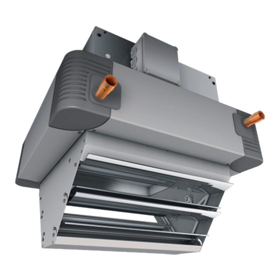
MultiMAXX HN Technical data Unit components Fig. 2-1: MultiMAXX HN unit components 1: Protection grille (part of the fan) 2a: Wide-blade fan 2b: Curved-blade fan 3a: Air inlet nozzle, short 3b: Air inlet nozzle, long 4: Fan enclosure 5: Cu/Cu heat exchanger 6: Heat exchanger casing Comfort 7: Secondary louvre - manual control 8: Terminal block (in a plastic box) -
Page 11: Material Specifications
MultiMAXX HN Material specifications Unit part Material Fan with protection grille Various materials Air inlet nozzle Galvanized sheet steel Fan chamber Galvanized sheet steel Heat exchanger Cu/Cu or Cu/Al or Fe/FeZn Heat exchanger casing galvanized steel or galvanized painted steel in the Comfort version, plastic corners Air outlet louvre galvanized steel or Al louvre slats + galvanized steel or Al louvre slats + sta-... -
Page 12: Unit Versions
MultiMAXX HN Unit versions Fig. 2-2: Heating unit with casing in Industry design, with se- Fig. 2-4: Heating unit with casing in Comfort design, with basic condary air louvre air louvre Fig. 2-3: Cooling unit with casing in Industry design, with con- Fig. - Page 13 MultiMAXX HN Fig. 2-6: Wall-mounted cooling unit with secondary Basic louv- Fig. 2-8: Wall-mounted cooling unit with secondary Basic louv- re, with gravity-flow condensate drainage re, with gravity-flow condensate drain Fig. 2-7: Ceiling-mounted cooling unit with four-side anemostat, Fig. 2-9: Ceiling-mounted cooling unit with secondary louvre, with gravity-flow condensate drain with condensate pump...
-
Page 14: Unit Description
MultiMAXX HN Unit description MultiMAXX HN heating (and possibly cooling) units consist of a fan and a heat exchanger in a galvanized (or painted) steel casing. If required, the heat exchanger casing may have a RAL- shade protective surface finish. The outlet side is fitted with one of several types of outlet louvre (see the type code). -
Page 15: Unit Dimensions
MultiMAXX HN Unit dimensions 2.6.1 Dimensions of MultiMAXX HN units, Cu/Al, Cu/Cu, Fe/Fe Zn heat exchangers (water used as a medium) Industry design version Minimum installation and operation space Condensate pan with drain 16 mm (only for unit function V) Minimum installation and operation space Comfort design version Fig. - Page 16 MultiMAXX HN 2.6.2 Dimensions of MultiMAXX HN units, Fe/Fe Zn heat exchanger (steam used as a medium) Industry design version Minimum installation and operation space Comfort design version Minimum installation and operation space Fig. 2-11: Heating unit dimensions and heat exchanger connection Dimensions [mm]/size 1026 1154...
-
Page 17: Heat Exchanger Outlet Connections
MultiMAXX HN Heat exchanger outlet connections Model size Number of rows Heat exchanger outlet connections/identification in the type code threaded rod/A (male) R 1" R 1 1/4" Cu/Cu Cu/Al threadless pipe/O * threaded rod/A (male) R 1" R 1" R 1 1/4" R 1 1/4"... -
Page 18: Acoustic And Electrical Data
MultiMAXX HN 2.10 Acoustic and electrical data Speed Total sound value Speed Total sound value Max. Max. Max. Max. power power Size Size cur- rev / Sound power Sound pres- rev / Sound power Sound pres- cur- input input dB(A) sure* dB(A) dB(A) sure* dB(A) -
Page 19: Condensate Pump
MultiMAXX HN 2.11 Condensate pump Cooling units may produce condensate, which is collected in the condensate pan. If a gravity-flow condensate drain is not provided, a condensate pump must be used. The pump will transport condensate to collection or waste outlet points. 2.11.1 Condensate drain function The condensate pan is connected to the condensate pump by a hose. - Page 20 MultiMAXX HN Technical data Values Maximum water volume 500 l/h Sound pressure level < 47 dBA (1 metre from the pump) Alarm sensor signal 1 A induction, 4 A ohmic Drain connection fitting 3/8“ Tab. 2-6: Condensate pump technical data Condensate pump capacity Condensate volume (l/h) Fig.
-
Page 21: Air Side Accessories
MultiMAXX HN 2.12 Air side accessories The following accessories are available for MultiMAXX HN units: Identification Order Design code Mixed air module, direct ZH#.200# Mixing outdoor and recirculating air; galvanized sheet metal, Al profile Mixed air module, lateral ZH#.210# Mixing outdoor and recirculating air; galvanized sheet metal, Al profile Shut-off damper ZH#.230#... -
Page 22: Ecodesign Requirements According To Commission Regulation (Eu) 2016/ 2281
MultiMAXX HN Attention! All other important data regarding air side accessories is provided in the “Design data brochure for MultiMAXX HN heating units" 2.13 Ecodesign Directive requirements pursuant to Commission Regulation (EU) 2016/ 2281 Values indicated in Table 2-9 are according to the requirements of Commission Reg- ulation (EU) 2016/2281 implementing EU Parliament and Council Directive 2009/125/ EC on defining the framework for determining requirements for Ecodesign-certified products related to energy consumption and Ecodesign-certified air heaters, cooling... -
Page 23: Shipping And Storage
MultiMAXX HN Shipping and storage Shipping The manufacturer’s instructions must be observed during shipping (see the symbols on the packaging). Attention! • Check the shipment for complete and correct contents against the delivery note. • For repeated shipping and storage use the original packaging! Damage to the unit! •... -
Page 24: Storage
MultiMAXX HN Fig. 3-2: Wrong manner of handling the unit Storage MultiMAXX HN heating units must be protected against humidity and contamination and stored in areas protected from weather conditions in compliance with environment parameters Class IE 12 according to CSN EN IEC 60721-3-1 ed. 2/ Attention! Permitted storage conditions: Air temperature: -25 °C to 40 °C... -
Page 25: Mounting
MultiMAXX HN Installation Installation site load-bearing capacity Attention! The site of installation must be suitable to permanently bear the load of the heating unit; if necessary, this must be checked by a structural engineer or a designer. The suspension brackets of MultiMAXX HN units are to be mounted by 2x 4 M8 rivet nuts on the sides of the fan enclosure (see Fig. -
Page 26: Wall Mounting
MultiMAXX HN Distance between ceiling-mounted units (see Fig. 4-2) In order for the entire room to be covered we recommend the following distances between units: 6 to 12 m 3 to 6 m Fig. 4-2: Distances between ceiling-mounted units For the method of mounting recirculation units on the ceiling using a ceiling suspension bracket (ZH#.560#) see Fig. -
Page 27: Safe Distance
MultiMAXX HN 10 to 15 m 5 to 7 m 8 to 11 m 8 to 11 m Fig. 4-3: Distances between wall-mounted units Air throw Air throw in wall-mounted units Max. air Size throw (m) - louvres U, W HN11 HN12 HN13... -
Page 28: Unit Mounting
MultiMAXX HN Installation of the unit Attention! Heating units mounted on the ceiling must always be in a horizontal position to allow the bleeding and emptying of the heat exchanger. Fixing points: Heating units must be secured at 4 fixing points at least. When welding the pipes onto the heat exchanger, be careful not to damage the paint on the unit’s casing, Damage to the unit! - Page 29 MultiMAXX HN Fig. 4-6: Ceiling mounting using a ceiling suspension bracket Fig. 4-8: Wall mounting using the Studio suspension bracket (ZH#.5601) (ZH#.5400) Fig. 4-7: Wall mounting using the Modular suspension bracket Fig. 4-9: Wall mounting using the Kompakt C suspension brac- (ZH#.5500) ket (ZH#.5300) FläktGroup DC-2011-0143-GB 2022-07/R6 •...
- Page 30 MultiMAXX HN ZH#.3500 ZH#.4900 ZH#.4900 ZH#.200# ZH#.360# ZH#.2500 2600 ZH#.560# Fig. 4-10: Ceiling mounting of an air mixing unit and accessories with a ceiling suspension brac- ket (ZH#.560#) ZH#.3100 ZH#.5100 ZH#.2900 ZH#.5505 ZH#.210# ZH#.360# ZH#.2500 Fig. 4-11: : Wall mounting of an air mixing unit and accessories with the Modular suspension bracket (ZH#.560#) Air mixing units have the accessories flange factory-fitted;...
-
Page 31: Media Connections
MultiMAXX HN Media connection Pipe connection Attention! The inlet and outlet pipes must be installed in such a way to prevent any mechanical tension on the heat exchanger and to allow easy access to the heating unit for maintenance and repair. Connecting pipes: It is necessary to bleed air from the connecting pipes and heat exchanger on site! Heating/cooling medium inlet/outlet: Observe the designation of the connec-... -
Page 32: Condensate Pump Connection
MultiMAXX HN Condensate pump connection The condensate pump and its components are supplied with the following compo- nents: pump holder, condensate pump, suction hose and necessary connection parts - 2 screws for mounting the pump holder onto ceiling-mounted units or 4 screws for wall-mounted units, 2 screws for attaching the holder to the condensate pump, 1 self- adhesive plastic sleeve. -
Page 33: Electrical Connections
MultiMAXX HN Electrical connections Risk of electrocution! The electrical installation may only be carried out by persons qualified pursuant to Section 6 of Regulation CUBP and CBU No. 50/78 Coll. Attention! When carrying out the electrical connection of the unit, it is necessary to observe operational safety regulations and the generally recognized rules of engineering practice. -
Page 34: Plastic Electrical Enclosure/Steel Electrical Enclosure
MultiMAXX HN 6.1.2 Electric motor protection Protection by thermal contact (AC-motors): As standard, all AC-motors of MultiMAXX HN unit fans are fitted with thermal protection contacts, which must be connected. When the maximum permitted temperature of the electric motor winding is exceeded, the motor is stopped by the MC4 electrical enclosure. -
Page 35: 3-Speed, 3-Phase Electric Motor 3 X 400 V (3 X 500 V), 50 Hz (Electric Motor Designation C, S, V) Wiring Diagram
MultiMAXX HN Attention! The plastic enclosure and fan switch do not always have free terminals for connec- ting electrical accessories! These must be provided by an additional electrical ter- minal block (supplied by the site contractor). 3-speed, 3-phase electric motor 3 x 400 V (3 x 500 V), 50 Hz (electric motor designation C, S, V) wiring diagram –... -
Page 36: 2-Speed, 3-Phase Electric Motor 3 X 400 V, 50 Hz (Electric Motor Designation A, B, R) Wiring Diagram
MultiMAXX HN 1-stage operation at high speed ( 1-stage operation at medium speed (YY) 1-stage operation at low speed ( Fig. 6-3: Wiring diagram – 1-stage operation Attention! The electric motor cannot be operated with only two phases, otherwise it might be damaged. -
Page 37: 1-Speed, 1-Phase Electric Motor 1 X 230 V, 50 Hz
MultiMAXX HN 6.4.2 1-stage operation at operating voltage 3 x 400 V - electric motor terminal block wiring diagram – power supply voltage: 3 + PE = 4-core cable – TC shielded line: 2-core cable 1-stage operation at high speed ( 1-stage operation at low speed ( ... - Page 38 MultiMAXX HN 6.5.2 1-stage operation at operating voltage 1 x 230 V - electric motor terminal block wiring diagram – power supply voltage: 2 + PE = 3-core cable – TC shielded line: 2-core cable 1-speed operation Fig. 6-7: Wiring diagram – 1-stage operation 1-speed EC-motor 1 x 230 V, 50 Hz (electric motor designation Y) wiring diagram –...
-
Page 39: 1-Speed Stepless Ec-Motor 1 X 230 V, 50 Hz (Electric Motor Designation Y) Wiring Diagram
MultiMAXX HN 3-speed stepless EC-motor 3 x 400 V, 50 Hz (electric motor designation Z) wiring diagram – motor operation contact – operating voltage: 3 x 400 V – with control unit MC 4 – power supply line: 3 + PE = 4-core cable –... -
Page 40: Overview Of Matrix Printed Circuit Boards
MultiMAXX HN Overview of MATRIX printed circuit boards MATRIX PCBs are installed in a steel electrical enclosure. The following overview des- cribes the various types of control board. To make the necessary connections, the following board diagrams indicate the relevant controller types. The controller type (e.g. - Page 41 MultiMAXX HN 6.8.2 MATRIX 2002 and MATRIX 3002 control system PCB MATRIX MATRIX 2002 3002 4002 4002+IO 2002 3002 4002 4002+IO – Power supply connection – Power supply connection – Secondary louvre connection (in combination with – Secondary louvre connection MATRIX 3000) –...
- Page 42 MultiMAXX HN 6.8.3 MATRIX 4002 and MATRIX 4002+IO control system PCB MATRIX MATRIX 2002 3002 4002 4002+IO 2002 3002 4002 4002+IO – Power supply connection – Power supply connection – Secondary louvre connection – Secondary louvre connection – Mixing damper connection –...
- Page 43 MultiMAXX HN 6.8.4 MATRIX 2003 and MATRIX 3003 control system PCB MATRIX MATRIX 2003 3003 4003 4003+IO 2003 3003 4003 4003+IO – Power supply connection – Power supply connection – Secondary louvre connection (in combination with – Secondary louvre connection MATRIX 3000) –...
- Page 44 MultiMAXX HN 6.8.5 MATRIX 4003 and MATRIX 4003+IO control system PCB MATRIX MATRIX 2003 3003 4003 4003+IO 2003 3003 4003 4003+IO – Power supply connection – Power supply connection – Secondary louvre connection – Secondary louvre connection – Mixing damper connection –...
- Page 45 MultiMAXX HN 6.8.6 MATRIX 4004 and MATRIX 4004+IO control system PCB MATRIX MATRIX 4004 4004+IO 4004 4004+IO – Power supply connection – Power supply connection – Secondary louvre connection – Secondary louvre connection – Mixing damper connection – External valve –...
-
Page 46: Controller/Room Temperature Sensor Location
MultiMAXX HN Controller/room temperature sensor location Controllers with an IP54 protection rating do not have an integrated room temperature sensor. Such controllers are supplied with an external room temperature sensor. Attention! The installation site of the room temperature sensor is crucial for the precise control of room temperature. - Page 47 MultiMAXX HN 6.9.1 Controller installation Attention! In this case an external room temperature sensor is necessary. Fig. 6-17: Opening the controller Pos. 1: Mounting plate Pos. 2: Top section • Using a screwdriver remove the top section from the rear of the controller as shown in Fig.
-
Page 48: Electrical Connections With Matrix
MultiMAXX HN 6.10 Electrical connections with MATRIX 6.10.1 Connecting the mains power for units with 230 V power supply MATRIX 2001 3001 4004 4004+IO Pos. 1: Power supply 230 V AC/50 Hz, protection on-site max. B 10 A Pos. - Page 49 MultiMAXX HN 6.10.2 Connecting the mains power for units with 400 V power supply MATRIX 2002 3002 4002 4002+IO 2003 3003 4003 4003+IO Pos. 1: Power supply 400 V AC/50 Hz, protection on-site max. B 16 A Pos.
- Page 50 MultiMAXX HN MATRIX 200 # 300 # 400 # 400#+IO Controller - heating unit - additional unit connection (without valve control) With MATRIX OP21 controllers it is only possible to operate units with MATRIX 200# controls. Up to 16 heating units may be connected to one OP21.
- Page 51 MultiMAXX HN MATRIX 200 # 300 # 400 # 400#+IO First unit with MATRIX 300# – additional unit with MATRIX 200# connection Units MATRIX 300# control systems can only be operated with units with MATRIX 200# control systems. •...
- Page 52 MultiMAXX HN MATRIX 200 # 300 # 400 # 400#+IO Controller-to-heating unit connection With MATRIX OP3#/44/5# controllers it is only possible to ope- rate units with MATRIX 3000/ 4000 controls. • Connect the bus lines according to the wiring diagram supplied.
- Page 53 MultiMAXX HN 6.10.5 Connecting an outdoor temperature sensor (optional) MATRIX 200 # 300 # 400 # 400#+IO Pos. 1: Connecting cable (see the note on page 49) • Connect the outdoor temperature sensor according to the wiring diagram supplied. Fig.
- Page 54 MultiMAXX HN 6.10.9 Connecting a supply air temperature sensor MATRIX 200 # 300 # 400 # 400#+IO Pos. 1: Connecting cable (see the note on page 49) • Connect the supply air temperature sensor according to the wiring diagram supplied.
- Page 55 MultiMAXX HN 6.10.12 Connecting functional inputs and outputs MATRIX 2001 3001 4001 4001+IO A functional input may be connected to provide various functi- ons depending on the version. To activate a function this contact must be: – closed in economy mode, –...
- Page 56 MultiMAXX HN 6.10.13 Secondary louvre connection MATRIX 200 # 3001 400 # 400#+IO • Connect secondary louvre according to the wiring diagram supplied. Fig. 6-33: Secondary louvre connection MATRIX 2002 3002 4002 4002+IO 2003 3003 4003 4003+IO 4004 4004+IO ...
- Page 57 MultiMAXX HN 6.10.16 Shut-off valve connection MATRIX 200 # 300 # 400 # 400#+IO 1 = 230 V 934### series valve 2 = 230 V return spring valve • Connect valve actuators according to the wiring diagram supplied.
-
Page 58: Matrix.net Network And Shielding Connection
MultiMAXX HN 6.11 MATRIX.Net network and shielding connection This chapter provides information on MATRIX.Net and the proper way of setting up a network. MATRIX.Net is a network which can be used to connect various FläktGroup control system components to each other via a data interface (network participants). Through this data interface participants exchange information necessary for control. - Page 59 MultiMAXX HN Group structure in the MATRIX 3000 system in combination with the MATRIX 2000 system A group can be created with MATRIX 2000 and MATRIX 3000 systems. Fig. 6-41 in the example shows a network consisting of a controller, MATRIX 2000 and MATRIX 3000 systems and various global modules.
- Page 60 MultiMAXX HN Group structure with MATRIX 3000 and/or MATRIX 4000 systems A group can be created with MATRIX 3000 and MATRIX 4000 systems. Fig. 6-42 The example shows a network consisting of a controller, MATRIX 3000 a MATRIX 4000 systems and various global modules. Group Network Unit 2...
- Page 61 MultiMAXX HN 6.11.2 MATRIX.Net network structure The network can consist of one or more (up to 16) groups. Global modules can be inte- grated in the network later. The network structure/network topology of MATRIX.Net must be performed in a linear manner – see “Network topology” on page 62. The maximum extent of the MATRIX.Net network is shown in Fig.
- Page 62 MultiMAXX HN 6.11.3 MATRIX.Net network topology The MATRIX.Net system may be built in a line structure or a line structure with a branch. All units with a MATRIX system have access to this data interface. To prevent reflections interfering with transmission the data interface must be termina- ted at each physical end.
- Page 63 MultiMAXX HN 6.11.5 Line structure with branches Fig. 6-45 shows a MATRIX.Net system in a line structure with a branch. The example shows the connection of the controller via a branch in multiple groups. The maximum permitted branch length is 25 metres. Group 1 Group 2 Group X...
- Page 64 MultiMAXX HN 6.11.6 MATRIX.Net network configuration Data cable To build a MATRIX.Net network use only twisted core shielded data transfer cables according to EN 50170. Attention! We recommend the following data cable: 2 x 2 x ... mm Line length Regardless of the cross section and the number of participants the maximum line length including branches must not exceed 600 m.
-
Page 65: Connecting The Mc4 Control Unit, Potentiometer Or Control System On Site
MultiMAXX HN 6.12 Connecting the MC4 control unit, potentiometer or control system on site Connect the control system via a terminal block. This is located in the plastic electrical enclosure or fan switch, mounted either on the left or right of the fan enclosure (depen- ding on the configuration of the medium connections). - Page 66 MultiMAXX HN Group of air mixing heating units MultiMAXX HN with control unit MC 4 Contact thermostat Room thermostat Intermediate terminal block Indication Power supply MC4 control unit Fig. 6-46: Group of air mixing heating units MultiMAXX HN with control unit MC 4 Control unit cables - number of cores MC4M3AC MC4M2AC...
- Page 67 MultiMAXX HN Group of recirculation heating units MultiMAXX HN with control unit MC 4 Contact thermostat Room thermostat Intermediate termi- nal block Indication Power supply MC4 control unit Fig. 6-47: Group of recirculation heating units MultiMAXX HN with control unit MC 4 Control unit cables - number of cores MC4U3AC MC4U2AC...
- Page 68 MultiMAXX HN Group of recirculation heating units MultiMAXX HN with EC-motor with speed control by potentiometer 950EC1 Intermediate termi- nal block 981880 Power supply 1x230 Cables - number of cores V/50 Hz or 3x400 V/ Cable 1 (Power supply) - 3 cores (1 x 230 V) 50 Hz - 5 cores (3 x 400 V) Potentiometer 950EC1...
-
Page 69: Mixing Chamber Damper And Shut-Off Damper Actuator Wiring Diagram
MultiMAXX HN 6.13 Mixing chamber damper and shut-off damper actuator wiring diagram The wiring diagram is always shown on the casing of the relevant actuator and mixing chamber. Actuator 230 V open/close Actuator 230 V, open/close Actuator 230 V, + end limit (ZH#.2#02) + potentiometer (ZH#.2#03) switch (ZH#.2#04) -
Page 70: Commissioning
MultiMAXX HN Commissioning Risk of electrocution! Before carrying out any work on the unit, ensure that the unit is disconnected from the power supply. Ensure that the unit is secured against being reconnected at an appropriate point on the power supply system! Risk of scalding! Before commencing work on heating units: Before any work on valves or inlet or outlet medium connection close the heating... -
Page 71: Bleeding Air From The System
MultiMAXX HN Bleeding air from the system • Open all shut-off and control valves. • Open the system air bleed screw. • Once only the heating/cooling medium flows out, close the air bleed valve. Condensate drain and condensate pump inspection Attention! The cooling operation causes the formation of condensate, even on non-insulated medium lines. -
Page 72: Operational Inspection Of Frost Protection (Only For Mixing Units)
MultiMAXX HN Operational inspection of frost protection (only for mixing units) Units with outdoor air supply are fitted with a frost protection thermostat. With the recommended installation set-up, according to Fig. 6-49, the frost protection sensor and assessment element shuts off the actuator’s power supply at temperatures below approx. -
Page 73: Operating Instructions
MultiMAXX HN Wall-mounted unit Ceiling-mounted unit Fig. 7-2: Manual adjustment of the secondary louvre 7.5.6 Differential pressure switch The differential pressure switch is activate when the final filter pressure drop setpoint is reached, and the indicator on control unit MC4####.##F indicates that the filter is clogged and needs replacement. -
Page 74: Termination Resistors
MultiMAXX HN Termination resistors MATRIX 200 # 300 # 400 # 400#+IO The printed circuit boards of the MATRIX 2000 control system are not equipped with termination resistors. The termination resistors on the OP21 controller must only be switched on or off if a MATRIX.Net network is being built, or an additional module such as clock, input or out- put modules is being connected. - Page 75 MultiMAXX HN MATRIX 200 # 300 # 400 # 400#+IO MATRIX 300#/4000# control system PCBs and MATRIX OP3#/44/5# controllers have termination resistors. The termination resistors are connected at the beginning and end of the line (see Fig. 7-4): •...
-
Page 76: Settings Addresses
MultiMAXX HN Address settings MATRIX 200 # 300 # 400 # 400#+IO The printed circuit boards of the MATRIX 2000 control system are not equipped with termination resistors. The appropriate group address must be assigned on the control panel. Single group (without networking multiple unit groups) •... - Page 77 MultiMAXX HN MATRIX 200 # 300 # 400 # 400#+IO The appropriate group address must be assigned on the control panel and the units of a group. Single group (without networking multiple unit groups) • On the control panel, set the address to “0” (factory default setting). •...
-
Page 78: Starting The Unit
MultiMAXX HN 7.10 Starting the unit Risk of electrocution! The terminal box is open. Tampering with the terminal box is prohibited! Before starting the unit the electrical enclosure must be properly closed. • Switch on the power supply. • The unit is started using a MATRIX series controller, a 983... series controller or an external controller. -
Page 79: Data Connectivity Check
MultiMAXX HN 7.11 Data connectivity check Risk of electrocution! Before remedying a data connectivity fault, disconnect the entire system from the power supply. Ensure that the unit is secured against being reconnected at an appropriate point on the power supply system. 7.11.1 Checking control cables MATRIX 200 #... -
Page 80: Checking Control Inputs And Outputs
MultiMAXX HN 7.12 Checking control inputs and outputs MATRIX 3000/4000 control systems have control inputs and outputs. When checking control inputs and outputs, pay attention to the factory settings. The type of function a control system features is indicated in the unit’s wiring diagram (located in the electrical enclosure). - Page 81 MultiMAXX HN 7.12.2 Enabling external control of the exhaust fan MATRIX 200 # 300 # 400 # 400#+IO Procedure • Start the unit and, if necessary, change the required temperature setting once the fan starts running. • Start the mixing chamber damper control. The damper opens. 7.12.3 Operation modes MATRIX 200 #...
-
Page 82: Functions When Used With Matrix
MultiMAXX HN 7.13 Functions when used with MATRIX 7.13.1 Fan for MATRIX 200# to 400# MATRIX 200 # 300 # 400 # 400#+IO Fan control depends on the configuration of the control system and the selected unit's control mode. - Page 83 MultiMAXX HN Delayed start function MATRIX 200 # 300 # 400 # 400#+IO In air mixing units the fan starts after a delay and the valve opens immediately provided that the outdoor temperature exceeds a certain level (default 10 °C). An outdoor tem- perature sensor is required for this function.
- Page 84 MultiMAXX HN 7.13.4 Condensate pump MATRIX 200 # 300 # 400 # 400#+IO The condensate pump is used to drain the condensate which is formed in cooling units. The condensate pump is started as necessary by the float switch integrated with the condensate pan.
- Page 85 MultiMAXX HN Default settings and inlet limit values: – Pre-set air temperature: 18.0°C – minimum inlet air temperature: 10.0°C – maximum inlet air temperature: 35.0°C With room temperature control it is also necessary to select whether the limit is fixed or variable.
- Page 86 MultiMAXX HN if an internal room temperature sensor is connected but no required room temperature is available, i.e. there is no controller (e.g. when the construction site is being dried). “Standby mode” is interrupted once the required room temperature is entered. 7.13.9 Room frost protection MATRIX 200 #...
- Page 87 MultiMAXX HN 7.13.12 Secondary louvre The secondary louvre supplies air treated by the heating unit into the room being hea- ted in an optimum manner. The secondary louvre control function sets the optimum angle of discharge of the rele- vant air flow rate (fan speed) at the current temperature. The room can thus be heated without a draught while at the same time minimizing the stack effect.
- Page 88 MultiMAXX HN Make the setting as follows: • Switch two-stage and three-stage fans to stage 2. • Switch stepless EC motors to stage 2 or set the fan speed (on the controller with display) to 66%. • Set the secondary louvre in the fine-adjustment menu until you reach the required draught-free condition.
-
Page 89: Maintenance And Troubleshooting
MultiMAXX HN Maintenance and troubleshooting Maintenance Attention! We recommend commissioning a service contractor trained by the manufacturer to carry out maintenance. Risk of electrocution! Disconnect the heating unit from the power supply and secure it against inadvertent reconnection! Risk of injury from rotating parts! Wait until the fan stops moving! Risk of scalding! Wait until the heat exchanger and heating unit cool down! - Page 90 MultiMAXX HN Regular maintenance interval schedule The following maintenance must be carried out at the intervals specified: Maintenance intervals Components Filter inspection Air intake inspection* Outlet louvre inspection* Fan/fan area inspection* Inspection of hydraulic line screw connections** Checking electrical connections Earthing inspection Air bleeding the heat exchanger** Inspection of the heat exchanger and main condensate...
-
Page 91: Quarterly Maintenance
MultiMAXX HN Quarterly maintenance 8.2.1 Filter replacement If the unit has a filter module, it is necessary to check the filter for cleanliness. When the pressure drop increases to the maximum level defined in the design, the filter must be replaced. If a unit with a filtration module has a differential pressure switch, this switch must be set to the value defined in the design. - Page 92 MultiMAXX HN Pos. 1: Filter chamber Pos. 2: Bag filter G2, G4 or F7 Loosen the filter chamber side panel (1) by turning the quick-release locks by 90°, tilt the side panel out, pull out the bag filter and replace it (2). Slide the bag filter into the filter body, close the filter chamber side panel and secure it by turning the quick-release lock by 90°.
-
Page 93: Six-Monthly Maintenance
MultiMAXX HN Six-monthly maintenance 8.3.1 Fan inspection Inspect the following: • the fan impeller for free movement • electric motor power supply cable to make sure it is not damaged • connection of the electric motor power supply cable in the unit’s terminal block Annual maintenance 8.4.1 Cleaning the heat exchanger The heat exchanger can be cleaned using a jet of pressurized air or by washing using... -
Page 94: Before A Period Of Cooling
MultiMAXX HN Before a period of cooling 8.5.1 Condensate pan cleaning Only for cooling units • Clean the condensate pan. • Check the condensate pan drain and clean if necessary. • Check whether condensate is draining from the pan properly and check the trap installed on site. -
Page 95: Troubleshooting
MultiMAXX HN Troubleshooting Fault Possible cause Action The fan is not working The unit has not been started Start the unit The fan switch (optional) is on The fan No power supply Check the circuit breaker/power supply speed switch (1-2-3) and I/0 switch LED connection (only qualified personnel) on control unit MC4 is not on Electrical cables not connected... - Page 96 MultiMAXX HN Fault Possible cause Action The required temperature level set on the Set the required temperature on the con- The unit is not cooling/is not cooling sufficiently (cooling medium) controller/thermostat is too high troller/thermostat to a lower level The controller/thermostat or the sensor is Put the controller/thermostat or the sensor placed in the flow of cool air such as by the at a more suitable location...
- Page 97 MultiMAXX HN Fault Possible cause Action The fan is not running The thermal protection contact (TC) of the Check the fan motor thermal protection electric motor or the condensate pump contact (connection) The red controller LED is flashing: alarm contact has opened Replace the power electronic/controller and/or fan motor (only qualified person- The fan was disconnected...
-
Page 98: Dismantling And Disposal
MultiMAXX HN Dismantling and disposal Dismantling and disposal Damage to the environment! MultiMAXX HN heating units can be dismantled and disposed of only by qualified personnel! Dismantling When dismantling a MultiMAXX HN, proceed as follows: Risk of electrocution! Before starting any work, disconnect the unit with from the power supply to prevent electric shocks. -
Page 99: Declaration Of Conformity
EC DECLARATION OF CONFORMITY pursuant to Directive 2006/42/EC of the European Parliament and of the Council (government regulation No. 176/2008 Coll.) (original EC Declaration of Conformity) 2020/043/5AB15601 Manufacturer: FläktGroup Czech Republic a.s., Slovanská 781, 463 12 Liberec XXV – Vesec, Czech Republic, IC (Company ID): 46708375 Entity authorized to compile technical documentation: FläktGroup Czech Republic a.s., Slovanská... - Page 100 WWW.FLAKTGROUP.COM MULTIMAXX HN FläktGroup is the European market leader for smart and energy efficient Indoor Air and Critical Air solutions to support every application area. We offer our customers innovative technologies, high quality and outstanding performance supported by more than a century of accumulated industry experience.
Need help?
Do you have a question about the MultiMAXX HN11 and is the answer not in the manual?
Questions and answers