
Related Manuals for MULTIQUIP Mikasa MVH120VGH


Summary of Contents for MULTIQUIP Mikasa MVH120VGH
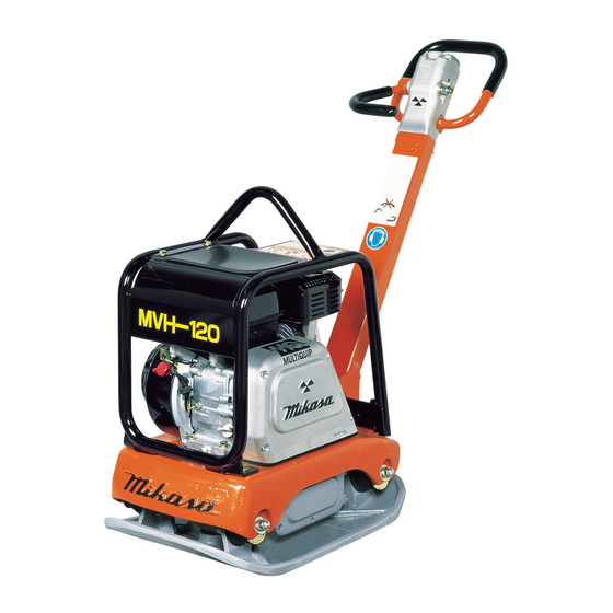
- Page 1 OPERATION AND PARTS MANUAL SERIES MODEL MVH120VGH REVERSIBLE PLATE COMPACTOR (HONDA GX160U1SMX4 GASOLINE ENGINE) Revision #2 (09/22/08) THIS MANUAL MUST ACCOMPANY THE EQUIPMENT AT ALL TIMES.
- Page 2 TABLE OF CONTENTS MVH120VGH PLATE HONDA GX160U1SMX4 DRAWINGS COMPACTOR Proposition 65 Warning ........... 2 Cylinder Head Assy.......... 42-43 Table of Contents ............ 4 Cylinder Barrel Assy......... 44-45 Parts Ordering Procedures ........5 Crankcase Cover Assy........46-47 Crankshaft Assy..........48-49 Safety Information ..........
- Page 3 SAFETY INFORMATION Do not operate or service the equipment before reading Potential hazards associated with the operation of this the entire manual. Safety precautions should be followed equipment will be referenced with hazard symbols which at all times when operating this equipment. may appear throughout this manual in conjunction with Failure to readand understand the safety safety messages.
- Page 4 NEVER lubricate components or attempt service on a running machine. NEVER use accessories or attachments that are not recommended by Multiquip for this equipment. Damage NOTICE to the equipment and/or injury to user may result. ALWAYS keep the machine in proper running condition.
- Page 5 SAFETY INFORMATION ENGINE SAFETY FUEL SAFETY WARNING DANGER DO NOT place hands or fingers inside engine DO NOT add fuel to equipment if it is placed inside truck compartment when engine is running. bed with plastic liner. Possibility exists of explosion or fire due to static electricity.
- Page 6 SAFETY INFORMATION BATTERY SAFETY (ELECTRIC START ONLY) TRANSPORTING SAFETY DANGER CAUTION DO NOT drop the battery. There is a possibility that the NEVER allow any person or animal to stand underneath battery will explode. the equipment while lifting. DO NOT expose the battery to open flames, NOTICE sparks, cigarettes, etc.
- Page 7 SPECIFICATIONS i f i o i t r t n u f i r b i i t a i l e ) n i e z i i t c t f . h / . ) h / i t a r b i i t a...
- Page 8 DIMENSIONS Figure 1. Compactor Dimensions r e f i r c i t p t r e a c i o i t i t r e a c i o i t i PAGE 12 — MVH120VGH PLATE COMPACTOR • OPERATION AND PARTS MANUAL — REV. #2 (09/22/08)
- Page 9 ANTI-VIBRATION HANDLE SYSTEM (AVT) DEFINITION OF PLATE COMPACTOR This compactor is equipped with advanced anti-vibration The Mikasa MVH120VGH is a walk-behind, reversible plate handle design that reduces vibration to the operator by up compactor designed for the compaction of sand and clay.
- Page 10 COMPONENTS REVERSE Figure 2. Compactor Components Figure 2 shows the location of the controls, indicators and general maintenance parts. The function of each control is described below: 7. Gasoline Engine – This plate compactor uses a 1. Breather Cap – Remove this cap to bleed (remove air) HONDA GX160 engine.
- Page 11 BASIC ENGINE Figure 3. Compactor Components The engine (Figure 3) must be checked for proper lubrication and filled with fuel prior to operation. Refer to the manufacturer's engine manual for instructions and details of operation and servicing. 7. Air Cleaner – Prevents dirt and other debris from 1.
- Page 12 INSPECTION BEFORE STARTING The Oil Alert system will automatically stop the engine before the engine falls 1. Read safety instructions at the beginning of manual. below safe limits. Always be sure to check the engine oil level prior to starting the 2.
- Page 13 INSPECTION 1. To check the V-belt tension (Figure 9), remove upper HYDRAULIC OIL CHECK belt cover. 1. With handle bar positioned vertically (storage position), remove the breather cap (Figure 7) from the breather plug. 2. Use a 24 mm wrench and remove breather plug (Figure 7).
- Page 14 OPERATION INITIAL STARTUP The CLOSED position of the choke lever enriches the fuel mixture for starting a CAUTION COLD engine. The OPEN position provides the correct fuel mixture for DO NOT attempt to run the compactor until the safety normal operation after starting and for and initial startup sections have been read.
- Page 15 OPERATION 6. If the engine has started, slowly return the choke lever 5. Firmly grasp the compactor's hand grip, the compactor (Figure 12) to the CLOSED position. If the engine has will begin moving in the desired position when the not started, repeat steps 1 through 5.
- Page 16 MAINTENANCE CAUTION Inspection and other services should always be carried out on solid and level ground with the engine shut down. INSPECTION AND MAINTENANCE TABLES 1. To make sure your plate compactor is always in good working condition before using, carry out the maintenance inspection in accordance with Tables 5 and 6.
- Page 17 MAINTENANCE ENGINE OIL REPLACEMENT Replacing the V-belt 1. Replace engine oil, in first 20 hours of operation and Remove the upper and lower belt covers. Engage an offset every 100 hours afterwards. wrench (13 mm) or the like to vibrator pulley (lower) fastening bolt.
- Page 18 MAINTENANCE STORAGE CAUTION For storage of the pump for over 30 days, the following is Make sure hydraulic oil in hand pump is at a normal required: save operating level. DO NOT over fill. Over filling (excessive oil) will cause excess oil to blow out of Drain the fuel tank completely.
- Page 19 TROUBLESHOOTING i t o i t u i r b i t a l t i s i f f " , l i a , e l t r o r i c i u c i f e e i c i t a l .
- Page 20 TROUBLESHOOTING i t o n i t i t u r i A r i a e l c " " r e i s s l e v o l f s u j , t n d l i t e r .
- Page 21 TROUBLESHOOTING i t o i t u t u l p i l s u j u l c p i l s u j . t l e v i l i O b i v l l i F e r r .
- Page 22 The contents and part numbers listed in the parts section are A blank entry generally indicates that the item is not sold subject to change without notice . Multiquip does not separately. Other entries will be clarified in the “Remarks”...
- Page 23 SUGGESTED SPARE PARTS MVH120VGH PLATE COMPACTOR WITH HONDA GX160U1SMX4 ENGINE 1 to 3 units QTY. DESCRIPTION 4 ..458450620 ....SHOCK ABSORBER 3 ..070100322 ....V-BELT 1 ..956100041 ....THROTTLE WIRE 3 ..9807955846 ....SPARK PLUG 1 ..28462ZH8003 ..... ROPE, RECOIL STARTER 3 ..
- Page 24 NAMEPLATE AND DECALS SHELL TELLUS OIL NPA-748 J OPERATIONAL CAUTION Prior to OPERATION: Check engine oil and fuel level if not enough, add to proper level To START engine: 1. Warm up engine at low speed for 3 to 5 minutes. 2.
- Page 25 NAMEPLATE AND DECALS PART NO PART NAME QTY. REMARKS 920207480 DECAL, SHELL TELLUS OIL 46 ....1 ....NPA-748 920207430 DECAL, CAUTION ........1 ....NPA-743 920203330 EAR PROTECTION LABEL ......1 ....DCL333 920201580 DECAL, MQ MARK 71X55 920207420 DECAL, V-BELT RPF-3320 ......
- Page 26 VIBRATING PLATE ASSY. (For Belt adjustment) PAGE 30 — MVH120VGH PLATE COMPACTOR • OPERATION AND PARTS MANUAL — REV. #2 (09/22/08)
- Page 27 VIBRATING PLATE ASSY. PART NO PART NAME QTY. REMARKS 458115140 VIBRATING PLATE 458450620 SHOCK ABSORBER MED55 M12 020312100 NUT M12 030212300 WASHER, LOCK M12 022131210 CAP NUT M12 030212300 WASHER, LOCK M12 952405600 WASHER 12.5X35X4.5 460449160 OIL GAUGE 953405260 PACKING 1/4 (CU) 952401190 WASHER 13X43X4.5 MVH120VGH •...
- Page 28 BODY ASSY. 12-1 12-2 12-3 12-4 12-6 12-7 12-8 PAGE 32 — MVH120VGH PLATE COMPACTOR • OPERATION AND PARTS MANUAL — REV. #2 (09/22/08)
- Page 29 BODY ASSY. PART NO PART NAME QTY. REMARKS 458119620 BASE 912216010 ENGINE AY GX160U1 001220835 BOLT 8X35 T 030208200 WASHER, LOCK M8 031108160 WASHER, FLAT M8 458214380 BELT COVER PLATE 001220820 BOLT 8X20 T 030208200 WASHER, LOCK M8 458451370 SPACER 202512 458337770 CLUTCH ASSY A112420 ......
- Page 30 VIBRATOR ASSY. 24 21 5 30 28 29 PAGE 34 — MVH120VGH PLATE COMPACTOR • OPERATION AND PARTS MANUAL — REV. #2 (09/22/08)
- Page 31 VIBRATOR ASSY. PART NO PART NAME QTY. REMARKS 458910011 VIBRATOR ASSY ........1 ....INCLUDES ITEMS W/ # 458115150 VIBRATING CASE 040406307 BEARING 6307C4 458337700 ROTARY SHAFT, DRIVE 458342580 ROTARY SHAFT, DRIVEN/NEW 080200350 STOP RING S35 951405460 KEY 10X8X19 RR 040306907 BEARING 6907C3 458337730...
- Page 32 CONTROL ASSY. PAGE 36 — MVH120VGH PLATE COMPACTOR • OPERATION AND PARTS MANUAL — REV. #2 (09/22/08)
- Page 33 CONTROL ASSY. PART NO PART NAME QTY. REMARKS 458119640 HANDLE VAS/ MVH-120,150 031110160 WASHER, FLAT M10 939010320 STOPPER RUBBER 45X36H 020410060 NUT M10, H=6 030210250 WASHER, LOCK M10 458338001 PUMP ASSY 458337430 TRAVEL LEVER 001520820 SOCKET HEAD BOLT 8X20 T 458451420 COLLAR 033910030...
- Page 34 CONTROL ASSY. PAGE 38 — MVH120VGH PLATE COMPACTOR • OPERATION AND PARTS MANUAL — REV. #2 (09/22/08)
- Page 35 CONTROL ASSY. CONTINUED PART NO PART NAME QTY. REMARKS 362910060 THROTTLE LEVER ASSY ......1 ....INCLUDES ITEMS W/ # 001520610 SOCKET HEAD BOLT 6X10 T 458461440 MOUNT NUT, THROTTLE 001520510 SOCKET HEAD BOLT 5X10 T 463455950 SPACER,THROTTLE 362341550 THROTTLE BODY 362910090 THROTTLE,GEAR CP,W/BOLT 362455630...
- Page 36 HAND PUMP ASSY. PAGE 40 — MVH120VGH PLATE COMPACTOR • OPERATION AND PARTS MANUAL — REV. #2 (09/22/08)
- Page 37 HAND PUMP ASSY. PART NO PART NAME QTY. REMARKS 458338001 PUMP ASSY ..........0 ....INCLUDES ITEMS W/ 458010150 CAM COMP (PUMP) ........1 ....INCLUDES ITEMS W/ # 458010100 COVER (HAND PUMP) 458010170 PISTON CP (PUMP) 458010110 CONTROL SHAFT (PUMP) 458010120 BUSH 042500607...
- Page 38 GX160U1SMX4 — CYLINDER HEAD ASSY. PAGE 42 — MVH120VGH PLATE COMPACTOR • OPERATION AND PARTS MANUAL — REV. #2 (09/22/08)
- Page 39 GX160U1SMX4 — CYLINDER HEAD ASSY. PART NO PART NAME QTY. REMARKS 12210ZH8405 HEAD COMP., CYLINDER ......1 ....INCLUDES ITEMS W/# 12204ZE1306 GUIDE, IN. VALVE (O.S.), OPTION 12205ZE1315 GUIDE, EX. VALVE (O.S.), OPTION ..1 ....INCLUDES ITEM W/% 12216ZE5300 CLIP, VLAVE GUIDE 12251ZF1800 GASKET, CYLINDER HEAD...
- Page 40 GX160U1SMX4 — CYLINDER BARREL ASSY. PAGE 44 — MVH120VGH PLATE COMPACTOR • OPERATION AND PARTS MANUAL — REV. #2 (09/22/08)
- Page 41 GX160U1SMX4 — CYLINDER BARREL ASSY. PART NO PART NAME QTY. REMARKS 12000ZH8426 BARREL ASSY., CYL. (OIL ALERT) ..1 ....INCLUDES ITEMS W/# 15510ZE1033 SWITCH ASSY., OIL LEVEL 16510ZE1000 GOVERNOR ASSY........1 ....INCLUDES ITEMS W/% 16511ZE1000 WEIGHT, GOVERNOR 16512ZE1000 HOLDER, GOVERNOR WEIGHT 16513ZE1000...
- Page 42 GX160U1SMX4 — CRANKCASE COVER ASSY. PAGE 46 — MVH120VGH PLATE COMPACTOR • OPERATION AND PARTS MANUAL — REV. #2 (09/22/08)
- Page 43 GX160U1SMX4 — CRANKCASE COVER ASSY. PART NO PART NAME QTY. REMARKS 11300ZZE1634 COVER ASSY. CRANKCASE ..... 1 ....INCLUDES ITEMS W/% 11381ZH8801 GASKET CRANKCASE 15600ZE1003 OIL GAUGE/CAP ASSY. (GRAY) ....1 ....INCLUDES ITEMS W/# 15600ZG4003 OIL PLUG ASSY........1 ....INCLUDES ITEMS W/+ 15625ZE1003 PACKING, OIL FILLER CAP 91201Z0T801...
- Page 44 GX160U1SMX4 — CRANKSHAFT ASSY. PAGE 48 — MVH120VGH PLATE COMPACTOR • OPERATION AND PARTS MANUAL — REV. #2 (09/22/08)
- Page 45 GX160U1SMX4 — CRANKSHAFT ASSY. PART NO PART NAME QTY. REMARKS 92101080250A BOLT 90473842000 WASHER 8 MM 90741883810 KEY 5X5X33 (YELLOW) 13310ZE1000 CRANKSHAFT COMP. MVH120VGH • OPERATION AND PARTS MANUAL — REV. #2 (09/22/08) — PAGE 49...
- Page 46 GX160U1SMX4 — PISTON ASSY. PAGE 50 — MVH120VGH PLATE COMPACTOR • OPERATION AND PARTS MANUAL — REV. #2 (09/22/08)
- Page 47 GX160U1SMX4 — PISTON ASSY. PART NO PART NAME QTY. REMARKS 13010ZL0003 RING SET, PISTON (STD) ......1 ....S/N 1120413 AND BELOW 13010Z4K004 RING SET, PISTON (STD) ......1 ....S/N 1120414 AND ABOVE 13011Z4K004 RING SET, PISTON (0.25) ......1 ....S/N 1120413 AND BELOW 13011ZL0003 RING SET, PISTON (0.25) ......
- Page 48 GX160U1SMX4 — CAMSHAFT ASSY. PAGE 52 — MVH120VGH PLATE COMPACTOR • OPERATION AND PARTS MANUAL — REV. #2 (09/22/08)
- Page 49 GX160U1SMX4 — CAMSHAFT ASSY. PART NO PART NAME QTY. REMARKS 14100ZE1812 CAMSHAFT ASSY........1 ....INCLUDES ITEM W/# 14410ZE1010 ROD, PUSH 14431ZE1000 ARM, VALVE ROCKER 14441ZE1010 LIFTER, VALVE 14451ZE1013 PIVOT, ROCKER ARM 14568ZE1000 SPRING, WEIGHT RETURN 14711ZF1000 VALVE, INLET 14721ZF1000 VALVE, EXHAUST 14751ZF1000...
- Page 50 GX160U1SMX4 — RECOIL STARTER ASSY. PAGE 54 — MVH120VGH PLATE COMPACTOR • OPERATION AND PARTS MANUAL — REV. #2 (09/22/08)
- Page 51 GX160U1SMX4 — RECOIL STARTER ASSY. PART NO PART NAME QTY. REMARKS 28400ZH8023ZB STARTER ASSY., RECOIL (BLACK) ..1 ....INCLUDES ITEMS W/# 28410ZH8003ZB CASE COMP., RECOIL STARTER NH1 28421ZH8801 REEL, RECOIL STARTER 28422ZH8801 RACHET STARTER 28431ZH8801 PLATE, FRICTION 28433ZH8801 GUIDE, RATCHET 28441ZH8801 SPRING, FRICTION 28442ZH8003...
- Page 52 GX160U1SMX4 — FAN COVER ASSY. PAGE 56 — MVH120VGH PLATE COMPACTOR • OPERATION AND PARTS MANUAL — REV. #2 (09/22/08)
- Page 53 GX160U1SMX4 — FAN COVER ASSY. PART NO PART NAME QTY. REMARKS 19610ZE1000ZC COVER COMP., FAN NH1 ......1 ....S/N 1120542 AND BELOW 19610ZE1010ZC COVER COMP., FAN NH1 ......1 ....S/N 1120543 AND ABOVE 19630ZH8000 SHROUD COMP. 36100ZF6P81 SWITCH ASSY. ENGINE STOP ....1 ....S/N 1145482 AND BELOW 36100ZF6P82 SWITCH ASSY.
- Page 54 GX160U1SMX4 — CARBURETOR ASSY. PAGE 58 — MVH120VGH PLATE COMPACTOR • OPERATION AND PARTS MANUAL — REV. #2 (09/22/08)
- Page 55 GX160U1SMX4 — CARBURETOR ASSY. PART NO PART NAME QTY. REMARKS 16010ZE1812 GASKET SET ..........1 ....INCLUDES ITEMS W/ & 16011ZE0005 FLOAT VALVE SET 16013ZE0005 FLOAT SET 16015ZE0831 FLOAT CHAMBER SET ......1 ....INCLUDES ITEMS W/ 5A& GASKET, FLOAT CHAMBER SET ..... 1 ....NOT SOLD SEPARATELY 16016ZH7W01 SCREW SET, PILOT 16024ZE1811...
- Page 56 GX160U1SMX4 — AIR CLEANER ASSY. PAGE 60 — MVH120VGH PLATE COMPACTOR • OPERATION AND PARTS MANUAL — REV. #2 (09/22/08)
- Page 57 GX160U1SMX4 — AIR CLEANER ASSY. PART NO PART NAME QTY. REMARKS 16271ZE1000 PACKING, ELBOW 17210ZE1505 CLEANER ELEMENT ......... 1 ....INCLUDES ITEMS W/# REPLACES 17210ZE1822 17218ZE1505 OUTER ELEMENT ........1 ....REPLACES 17218ZE1821 17230ZE1820 COVER, AIR CLEANER 17232891000 GROMMET, AIR CLEANER 17238ZE7010 COLLAR, AIR CLEANER 17239ZE1000...
- Page 58 GX160U1SMX4 — MUFFLER ASSY. PAGE 62 — MVH120VGH PLATE COMPACTOR • OPERATION AND PARTS MANUAL — REV. #2 (09/22/08)
- Page 59 GX160U1SMX4 — MUFFLER ASSY. PART NO PART NAME QTY. REMARKS 18310ZH8810 MUFFLER COMP. 19320ZF1H01 PROTECTOR, MUFFLER 18340ZE1010 DEFLECTOR COMP. 18355ZE1000 ARRESTOR, SPARK 18381ZH8800 GASKET, MUFFLER 18522ZE1000 GUIDE, MUFFLER 90002ZG0003 SCREW, TAPPING 4X8 90050ZE1000 SCREW, TAPPING 5X8 90055ZE1000 SCREW, TAPPING 4X6 020108060 NUT, HEX 8MM ..........
- Page 60 GX160U1SMX4 — FUEL TANK ASSY. PAGE 64 — MVH120VGH PLATE COMPACTOR • OPERATION AND PARTS MANUAL — REV. #2 (09/22/08)
- Page 61 GX160U1SMX4 — FUEL TANK ASSY. PART NO PART NAME QTY. REMARKS 17620Z0T305 CAP COMP., CHROME PLATED ....1 ....S/N 1125014 AND BELOW INCLUDES ITEM W/+ 17620Z4H000 CAP COMP., CHROME PLATED ....1 ....S/N 1125015 AND ABOVE INCLUDES ITEM W/% 17631Z0T812 PACKING, FUEL FILLER CAP ....
- Page 62 GX160U1SMX4 — FLYWHEEL ASSY. PAGE 66 — MVH120VGH PLATE COMPACTOR • OPERATION AND PARTS MANUAL — REV. #2 (09/22/08)
- Page 63 GX160U1SMX4 — FLYWHEEL ASSY. PART NO PART NAME QTY. REMARKS 31100ZE1010 FLYWHEEL COMP. 13331357000 WOODRUFF KEY 25X18 19511ZE1000 FAN, COOLING 28451ZH8801 PULLEY, STARTER 90201878003 SPECIAL NUT 14MM MVH120VGH • OPERATION AND PARTS MANUAL — REV. #2 (09/22/08) — PAGE 67...
- Page 64 GX160U1SMX4 — IGNITION ASSY. PAGE 68 — MVH120VGH PLATE COMPACTOR • OPERATION AND PARTS MANUAL — REV. #2 (09/22/08)
- Page 65 GX160U1SMX4 — IGNITION ASSY. PART NO PART NAME QTY. REMARKS 36101ZE1010 CORD, STOP SWITCH (370 MM) 30600ZE1013 CAP ASSY., NOISE SUPPRESSOR 30500ZE1063 COIL ASSY., IGNITION ......1 ..S/N 1141205 AND BELOW 30500ZE1073 COIL ASSY., IGNITION ......1 ..S/N 1141206 AND ABOVE 90121952000 FLANGE BOLT 6X25 MVH120VGH •...
- Page 66 GX160U1SMX4 — CONTROL ASSY. PAGE 70 — MVH120VGH PLATE COMPACTOR • OPERATION AND PARTS MANUAL — REV. #2 (09/22/08)
- Page 67 GX160U1SMX4 — CONTROL ASSY. PART NO PART NAME QTY. REMARKS 16500ZH8U43 CONTROL ASSY........1 ....INCLUDES ITEMS W/# 90013883000 FLANGE BOLT 6X12 16561ZE1020 SPRING, GOVERNOR 90015ZE5010 BOLT, GOVERNOR ARM 16551ZE0010 ARM, GOVERNOR 9405006000 NUT, FLANGE 6 MM 16562ZE1020 SPRING, THROTTLE RETURN 16555ZE1000 ROD, GOVERNOR 93500040060H...
- Page 68 GX160U1SMX4 — LABEL ASSY. PAGE 72 — MVH120VGH PLATE COMPACTOR • OPERATION AND PARTS MANUAL — REV. #2 (09/22/08)
- Page 69 GX160U1SMX4 — LABEL ASSY. PART NO PART NAME QTY. REMARKS 87528ZH7000 MARK, CHOKE (GRAY) 87516ZH7810 MARK, OPERATOR CAUTION (ENGLISH) 1 87532ZH7000 MARK, THROTTLE INDICATION 87521ZH8030 EMBLEM (GX160 5.5) ........ 1 ....S/N 1120413 AND BELOW 87521ZH8040 EMBLEM (GX160 5.5) ........ 1 ....S/N 1120414 AND ABOVE MVH120VGH •...
- Page 70 GX160U1SMX4 — TOOLS ASSY. PAGE 74 — MVH120VGH PLATE COMPACTOR • OPERATION AND PARTS MANUAL — REV. #2 (09/22/08)
- Page 71 GX160U1SMX4 — TOOLS ASSY. PART NO PART NAME QTY. REMARKS 89218ZE1000 WRENCH COMPLETE, SPARK PLUG 89219805000 HANDLE, BOX WRENCH MVH120VGH • OPERATION AND PARTS MANUAL — REV. #2 (09/22/08) — PAGE 75...
Need help?
Do you have a question about the Mikasa MVH120VGH and is the answer not in the manual?
Questions and answers