Advertisement
Quick Links
REV.
Description
REV.
首次发行(据 SolaX320101105500)
00
周雯
2024/08/16
说明书 X3-Genki 系列(内部 X3-NEO-LV)
描述
英文版 巴基斯坦 Renewable power
浙江艾罗网络能源技术股份有限公司
料号
SolaX Power Network Technology
320101115300
(Zhejiang) Co., Ltd.
单位
页次
mm
Description
技术要求:
1. 封面封底 157g 铜版纸覆哑膜彩打,内部纸 80g 双胶纸黑白印刷,正反打印;
2. 装订方式:胶装或骑马钉,内页大于 60 页时须胶装;
3. 未注尺寸公差按 ±3 mm;
4. 图面、字体印刷清晰、无偏移、无毛边、不起边、油墨不脱落;
5. 黑色字体颜色为 PANTONE BLACK C, 无边框,底色为白色;
6. 符合 ROHS 要求。
143 mm
X3-Genki
User Manual
5kW / 8kW / 10kW / 12kW / 15kW
Scan QR Code for eManual
说明书 X3-Genki 系列(内部 X3-NEO-LV)英文版
描述
巴基斯坦 Renewable power
材料
双胶纸
料号
320101115300
单位
页次
mm
设计
周 雯 2024/08/16
审核
陈 齐 2024/08/16
核准
施鑫淼 2024/08/16
浙江艾罗网络能源技术股份有限公司
Advertisement

Related Manuals for SolaX Power Fronus X3-Genki-5K


Summary of Contents for SolaX Power Fronus X3-Genki-5K
- Page 1 巴基斯坦 Renewable power 6. 符合 ROHS 要求。 审核 陈 齐 2024/08/16 说明书 X3-Genki 系列(内部 X3-NEO-LV) 描述 材料 核准 双胶纸 施鑫淼 2024/08/16 英文版 巴基斯坦 Renewable power 浙江艾罗网络能源技术股份有限公司 料号 SolaX Power Network Technology 320101115300 料号 320101115300 (Zhejiang) Co., Ltd. 浙江艾罗网络能源技术股份有限公司 单位 页次 单位 页次...
- Page 3 X3-Genki User Manual 5kW / 8kW / 10kW / 12kW / 15kW Scan QR Code for eManual...
- Page 5 STATEMENT Copyright Copyright © FRONUS SOLAR ENERGY (WASIQ TRADERS). All rights reserved. No part of this manual may be reproduced, transmitted, transcribed, stored in a retrieval system, or translated into any language or computer language, in any form or by any means without the prior written permission of FRONUS SOLAR ENERGY (WASIQ TRADERS).
- Page 6 About This Manual Scope of Validity This manual is an integral part of X3-Genki series inverter. It describes the transportation, storage, installation, electrical connection, commissioning, maintenance and troubleshooting of the product. Please read it carefully before operating. This manual is valid for the following inverter models: •...
- Page 7 Conventions The symbols that may be found in this manual are defined as follows. Symbol Description Indicates a hazardous situation which, if not avoided, DANGER will result in death or serious injury. Indicates a hazardous situation which, if not avoided, WARNING could result in death or serious injury.
- Page 8 Table of Contents Safety ......................1 1.1 General Safety ........................1 1.2 Safety Instructions of PV and Inverter .................1 1.2.1 Safety Instructions of PV ..................2 1.2.2 Safety Instructions of Inverter ................2 Product Overview ..................4 2.1 Product Introduction ......................4 2.2 Appearance .........................4 2.3 Symbols on the Label and Inverter ................5 2.4 Working Principle .......................6 2.4.1 Working Principle ....................6...
- Page 9 8.2 PE Connection ........................29 8.3 Battery Power Cable Connection .................31 8.4 AC Connection ........................34 8.5 PV Connection ........................39 Communication Connection ..............43 9.1 Pin Assignment of COM Terminal .................43 9.2 Battery Communication Connection ................44 9.3 Battery Temperature Sensor Connection ..............47 9.4 Upper Cover Installation ....................49 9.5 Monitoring Connection ....................50 System Commissioning ................53 10.1 Checking before Power-on ....................53...
- Page 10 Decommissioning ..................79 14.1 Disassembling the Inverter .....................79 14.2 Packing the Inverter ......................80 14.3 Disposing of the Inverter ....................80 Technical Data ..................81...
- Page 11 Safety General Safety The series inverter has been meticulously designed and thoroughly tested to comply with the relevant state and international safety standards. Nevertheless, like all electrical and electronic equipment, safety precautions must be observed and followed during the installation of the inverter to minimize the risk of personal injury and ensure a safe installation.
- Page 12 Safety 1.2.1 Safety Instructions of PV DANGER! Potential risk of lethal electric shock associated with the photovoltaic (PV) system • Exposure to sunlight can result in the generation of high DC voltage by PV modules, which can lead to electric shock causing severe injuries or even death. •...
- Page 13 Safety WARNING! Potential danger of scalding due to the hot enclosure of the inverter • Avoid touching the inverter while it is running, as it becomes hot during operation and may cause personal injuries. WARNING! • When handling the battery, carefully follow all safety instructions provided in the battery manual.
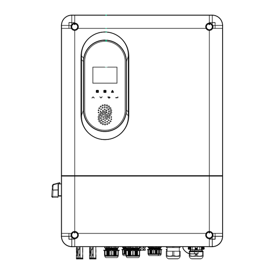
- Page 14 Product Overview Product Introduction The X3-Genki series supports various intelligent solutions such as load management, wireless metering, dual battery terminals, etc. to achieve efficient and economical energy utilization. The X3-Genki series inverter is compatible with both Lithium-ion batteries and lead-acid batteries. Appearance LCD panel Nameplate...
- Page 15 Product Overview Item Description Button pressed: ON, the system is allowed to operate; Button System switch released: OFF, the system is not allowed to operate (no voltage output from EPS, and BAT terminals). Including PV terminals, battery terminals, GEN terminals, EPS Wiring area terminals, communication terminals, etc.
- Page 16 Product Overview Working Principle 2.4.1 Working Principle The inverter is equipped with multi-channel MPPT for DC input to ensure maximum power even under different photovoltaic input conditions. The inverter unit converts direct current into alternating current and supplies the load. 2.4.2 Application Schemes Main Breaker/RCD...
- Page 17 Product Overview Main Breaker/RCD Inverter E-N LINK N-BAR ⋯ ⋯ E-BAR Breaker BAT1 Breaker Battery Do not connect this terminal when the neutral BAT2 wire and PE wire are connected together. Distribution Box Figure 2-4 Neutral point connected to PE in distribution box Main Breaker/RCD Inverter Breaker...
- Page 18 Product Overview Working State The series inverter has Wait, Check, Normal, Fault, Update, EPS Check, EPS Wait, EPS, GEN Check, GEN, Idle Standby and Force Wakeup state. Table 2-3 Description of working state State Description • The inverter is waiting for the conditions to be met in order to Wait enter Checking state.
- Page 19 System Overview System Overview Computer CLOUD PV modules Dongle Phone Backup Load X3-Genki series Battery 1 Battery 2 Adapter Box Smart Load Generator (Optional) (Optional) (Optional) Cloud Figure 3-1 System diagram...
- Page 20 System Overview Table 3-1 System item description Item Description PV modules PV modules work in MPPT mode. The series inverter can be conencted with lithium-ion batteries or lead-acid batteries. Lithium-ion batteries communicate with the Battery inverter through the BMS. With FRONUS Adapter Box G2, you can connect the smart heat Adapter Box G2 pump to the energy storage systems, realizing the control of the (Optional)
- Page 21 Transportation and Storage If the inverter is not put into use immediately, the transportation and storage requirements need to be met: Transportation • Observe the caution signs on the packaging of inverter before transportation. • Pay attention to the weight of the inverter. Carry the inverters by the required number of personnel as specified by local regulations.
- Page 22 Preparation before Installation Selection of Installation Location The installation location selected for the inverter is quite critical in the aspect of the guarantee of machine safety, service life and performance. It has the IP65 ingress protection, which allows it to be installed outdoor. The installation position shall be convenient for wiring connection, operation and maintenance.
- Page 23 Preparation before Installation NOTICE! • For outdoor installation, precautions against direct sunlight, rain exposure and snow accumulation are recommended. • Exposure to direct sunlight raises the temperature inside the device. This temperature rise poses no safty risks,but may impact the device performance. •...
- Page 24 Preparation before Installation 5.1.2 Installation Carrier Requirement The installation carrier must be made of a non-flammable material, such as solid brick, concrete, etc. and be capable of supporting the weight of the inverter and suitable of the dimensions of the inverter . If the wall strength is not enough (such as wooden wall, the wall covered by a thick layer of decoration), it must be strengthened additionally.
- Page 25 Preparation before Installation 350 mm 350 mm 600 mm 350 mm 600 mm 350 mm Multiple inverters Figure 5-5 Clearance requirement for multiple inverters...
- Page 26 Preparation before Installation Tools Requirement Installation tools include but are not limited to the following recommended ones. If necessary, use other auxiliary tools on site. Please note that the tools used must comply with local regulations. Hammer drill Multimeter (drill bit: Ø10 mm) Measuring tape Utility knife (≥...
- Page 27 Preparation before Installation Additionally Required Materials Table 5-1 Additionally required wires Conductor Required Material Type Cross-section Dedicated PV wire with a voltage rating of 1000 V, a PV wire temperature resistance of 4-6 mm² °C, a fire resistance grade of VW-1 Communication wire Network cable CAT5E GEN and EPS wire...
- Page 28 Unpacking and Inspection Unpacking • The inverter undergoes 100% testing and inspection before delivery. However, damages may still occur during transportation. Before unpacking, please carefully check the external packaging for any signs of damage, such as punctures or cracks. • Unpacking the inverter according to the following figure.
- Page 29 Unpacking and Inspection Scope of Delivery Positive PV connector Negative PV connector Positive PV pin contact Negative PV pin contact Bracket Inverter Battery temperature Disassembling tool Self-tapping screw sensor for PV terminal Expansion tube Battery connection terminal OT terminal (21.8*8 mm) OT terminal (32.8*16 mm) M6*14 Screw (43.8*17.8 mm)
- Page 30 Unpacking and Inspection Item Description Quantity Remark 1 pc Temperature sensor for lead-acid Battery temperature sensor 1 pc batteries Disassembling tool for PV 1 pc terminal Self-tapping screw 6 pcs Bracket mounting Expansion tube 6 pcs 1 pc for grounding the inverter casing M6*14 Screw 3 pcs...
- Page 31 Mechanical Installation WARNING! • Only qualified personnel are allowed to perform the mechanical installation in accordance with local laws and regulations. • Check the existing power cables or other piping in the wall to prevent electric shock or other damage. •...
- Page 32 Mechanical Installation Dimensions for mounting Before installation, check the dimensions of the wall mounting bracket and ensure that enough space is reserved for the installation and heat dissipation of the entire system. Figure 7-3 Dimensions 1 (Unit: mm) Figure 7-4 Dimensions 2 (Unit: mm)
- Page 33 Mechanical Installation Installation procedures Step 1: Horizontally align the wall mounting bracket with the wall, adjust the position of the bracket with a spirit level until the bubble stays in the middle, and then mark holes. Please note that take the height of the battery into account when determining the position of the wall mounting bracket.
- Page 34 Mechanical Installation Step 4: Use expansion screws (part H) to attach the wall mounting bracket on the wall again and secure them to the wall by torque wrench. Figure 7-8 Securing the wall mounting bracket Step 5: Open the anti-static bag, take out the inverter. Lift up the inverter collaboratively by the required number of personnel in accordance with the local regulation and hang it onto the wall mounting bracket.
- Page 35 Mechanical Installation Step 6: Use M6*14 screws (part J) to secure the inverter on both sides. 1.5±0.1 N·m Figure 7-10 Securing the inverter (Right side) Figure 7-11 Securing the inverter (Left side) Step 7: (Optional) For safety reason, install an anti-theft lock. The anti-theft lock is not in the scope of delivery.
- Page 36 Electrical Connection DANGER! • Before electrical connection, make sure the DC switch, System Switch and AC breaker are disconnected. Otherwise, the high voltage may cause electric shock, resulting in severe personal injuries or even death. WARNING! • Only qualified personnel are allowed to perform the electrical connection following local laws and regulations.
- Page 37 Electrical Connection Table 8-1 Description of terminals Item Description Remarks Ground connection point DC switch PV input terminal COM 1 communication terminal COM 2 communication terminal EPS connection terminal GEN connection terminal Dongle terminal Battery connection terminal 8.1.2 Cable Connections of Inverter Figure 8-2 Cable connections of inverter...
- Page 38 Electrical Connection Table 8-2 Dsecriptons of connected part Item Part Description Source Refer to "5.3 Additionally Required Prepared by AC swicth Materials" for the recommended user specifications of AC switch. A PV string is composed of the PV Prepared by PV module modules connected in series.
- Page 39 Electrical Connection Item Cable Type and specifications Source Communication cable Prepared by user Refer to "5.3 Additionally Required Materials" Communication cable Prepared by user Battery communication In the battery accessory cable (lithium battery) package. Battery temperature In the inverter accessory sensor(lead-acid battery) package.
- Page 40 Electrical Connection Step 3: Crimp it with crimping tool. Figure 8-5 Crimping the cable Step 4: Connect the assembled PE cable to the grounding point of the inverter, and secure it with M6*14 screw (Part J). (Torque: 1.5±0.1 N·m) M6*14 1.5±0.1 N·m Figure 8-6 Securing the PE cable...
- Page 41 Electrical Connection Battery Power Cable Connection DANGER! • Before connecting the cables, make sure the breaker, power button (if any) and DC switch (if any) of battery is OFF. • Always ensure correct polarity. Never reverse the polarity of the battery cables as this will result in inverter damage.
- Page 42 Electrical Connection Step 2: Use a Phillips screwdriver to remove the protective cover inside the inverter. Please store it properly after removal. Figure 8-8 Remove the protective cover Step 3: Strip the insulation of the battery power cable to an appropriate length. Figure 8-9 Stripping the battery cable Step 4: Insert the stripped cable into the battery connection terminal (part M).
- Page 43 Electrical Connection Step 5: Loosen the swivel nut of the battery terminals then remove the screws. Figure 8-11 Threading the battery cable Step 6: Thread the cable through the swivel nut, puncture a waterproof seal, then pass through the BAT terminal. Connect the positive and negative cables to their respective positions, screw back the removed screws (Torque: 5.0±0.1 N·m).
- Page 44 Electrical Connection AC Connection The inverter supports the EPS mode. Requirements for AC connection • Residual Current Device (RCD) » The inverter does not require an external RCD when operating. If an external RCD is required by local regulations, a 300 mA Type-A RCD is recommended. If required by local regulations, a Type-B RCD is also permitted.
- Page 45 Electrical Connection Table 8-4 EPS load information Type of load Equipment Start power Lamp Rated power Resistive load Rated power Hair dryer Rated power Refrigerator 3-5 times rated power Air conditioner 3-6 times rated power Inductive load Washing machine 3-5 times rated power Microwave oven 3-5 times rated power * Refer to the nominal start power of the equipment for the actual start power.
- Page 46 Electrical Connection Step 2: Strip the insulation layer of L1, L2, L3, N and the grounding conductor to a length of 10±0.5 mm Figure 8-15 Strip the insulation Step 3: Pull the heat-shrink tubing over the cable and insert the stripped section into the OT terminal (part K).
- Page 47 Electrical Connection Figure 8-18 Shrinking the tubing Step 5: Remove the swivel nut of GEN and EPS terminal. Remove the sealing ring which will be no longer used. Remove Remove Figure 8-19 Removing the swivel nut Step 6: (Optional) GEN terminal connection. Thread the crimped cables through the swivel nut and terminal.
- Page 48 Electrical Connection Step 7: EPS terminal connection. Thread the crimped cables through the swivel nut and terminal. Insert the conductors into the terminal block and tighten the terminal block screws (Torque: 0.9 ± 0.1 N·m). Ensure that the conductors are firmly seated in the terminal.
- Page 49 Electrical Connection PV Connection DANGER! • When exposed to the sunlight, PV modules will generate lethal high voltage. Please take precautions. • Before connecting the PV modules, make sure that both DC switch and AC breaker are disconnected, and that the PV module output is securely isolated from the ground.
- Page 50 Electrical Connection Wiring procedures Step 1: Strip the insulation of the PV cables to an appropriate length. 4-6 mm Figure 8-22 Stripping the PV cable Step 2: Insert the stripped cable into the PV pin contact (part E). Make sure the the PV cable and PV pin contact are of the same polarity.
- Page 51 Electrical Connection Step 4: Thread the PV cable through swivel nut and insert the cable into the PV connector (part A, B, C, D). Figure 8-25 Threading the PV cable Step 5: A "Click" will be heard if it is connected correctly. Gently pull the cable backward to ensure firm connection.
- Page 52 Electrical Connection NOTICE! • If the voltage reading is negative, it indicates an incorrect DC input polarity. Please check if the wiring connections on the measuring device are correct or PV connectors are not mistakenly connected. Step 7: Use the PV removal tool (part G) to remove the PV terminal caps and connect the assembled PV connectors to the corresponding terminals until there is an audible "Click".
- Page 53 Communication Connection Pin Assignment of COM Terminal Battery communication or battery temperature sensor connection via BMS terminal, CT/ Meter connection via CT/METER terminal. COM 3: NG COM 1: EPO COM 2: DS 485 COM 4: I/O 1: RED-485B 1: WIFI-485B 1: 1DI-1 2: RED-485A 2: WIFI-485A...
- Page 54 Communication Connection NOTICE! • When using the Lithium battery, refer to "9.2 Battery Communication Connection" wiring procedure; when using lead-acid batteries, refer to "9.3 Battery Temperature Sensor Connection". Battery Communication Connection Connection diagram COM5 *For detailed connections on the battery side, please refer to the relevant documentation for the battery.
- Page 55 Communication Connection Wiring procedure Step 8: Loosen the swivel nut on the enclosure, and then remove the sealing plugs from the cable support sleeve as needed. Do not remove the sealing plugs from holes if you choose not to connect the cable. Remove Figure 9-31 Disassembling the connector Step 9: Find the battery communicaiton cable in the battery accessory package.
- Page 56 Communication Connection Step 11: Insert the stripped section into the RJ45 terminals (part O). Crimp it tightly with a crimping tool for RJ45. Pay attention to the pin order of RJ45 terminals. Use a network cable tester to check if the cable has been correctly and properly crimped before connecting to inverter.
- Page 57 Communication Connection Battery Temperature Sensor Connection Connection diagram Battery temperature sensor (part F) COM5 Figure 9-36 Battery temperature sensor connection diagram Wiring procedure Step 1: Loosen the swivel nut, and then remove the sealing plugs from the cable support sleeve as needed. Do not remove the sealing plugs from holes if you choose not to connect the cable.
- Page 58 Communication Connection Step 3: Insert the RJ45 connector into the COM 5 located inside the inverter. You will hear an audible "Click" . Step 4: Connect the other end to the lead-acid battery, ensuring that the battery temperature is measured. Figure 9-38 Connecting the NTC Figure 9-39 Crimping the RJ45...
- Page 59 Communication Connection Upper Cover Installation Step 1: After the connection is completed, replace the upper cover as follows (Torque: 2.8±0.1 N·m). M6*L14 2.8 ± 0.1 N·m Figure 9-40 Install the upper cover Step 2: Install the screw cover (part P) into the hole position on the upper cover. Figure 9-41 Install the upper cover...
- Page 60 Communication Connection Monitoring Connection The inverter provides a Dongle terminal, which can transmit data of the inverter to the monitoring website via WiFi+LAN dongle (Optional). The WiFi+LAN dongle is equipped with two kinds of communication modes (Wi-Fi mode or LAN mode). Users can choose based on actual needs.
- Page 61 Communication Connection Monitoring wiring procedure Wi-Fi mode: Assemble the dongle. M2.5 0.8 ± 0.1 N·m Figure 9-44 Assembling the dongle Plug the dongle to the inverter. Figure 9-45 Dongle connection procedure CAUTION! • The buckles on the inverter and dongle must be on the same side. Otherwise, the dongle may be damaged.
- Page 62 Communication Connection LAN mode: Disassemble the waterproof connector into components 1, 2, 3 and 4; Component 1 is not used. Keep it in a safe place. Figure 9-46 Disassembling the waterproof connector Assemble the dongle. M2.5 0.8 ± 0.1 N·m Figure 9-47 Assembling the dongle Plug the dongle to the inverter.
- Page 63 10 System Commissioning 10.1 Checking before Power-on Item Checking details The inverter is installed correctly and securely. Installation The battery is installed correctly and securely. Other device (if any) is installed correctly and securely. All DC, AC cables and communication cables are connected Wiring correctly and securely;...
- Page 64 System Commissioning 10.2 Powering on the System Step 1: Turn on the DC switch and check the LCD screen. Figure 10-48 Turn on the DC switch » If the LCD screen is not on, turn off the DC switch and check whether the PV polarity is connected correctly.
- Page 65 System Commissioning Step 4: Press the system switch down to the ON. Step 5: Switch on the system switch on the LCD. Return Inverter Inv VoL: 0.2 V Inv Curr: 1.00 A Inv Power: 0.00 kW Today: 0.0 kWh Total: 0.0 kWh Step 6: Wait for the inverter to start up.
- Page 66 11 Operation on LCD 11.1 Introduction of Control Panel The default menu is shown as below. In this interface, you can tap on the four icons of PV, battery and load to check the basic information of each part. LCD screen Error indicator light Operating indicator light Battery indicator light...
- Page 67 Operation on LCD Table 11-1 Definition of indicators LED indicator Status Definition Light on The inverter is in a normal state. Blinking The inverter is in the process of EPS. Operating The inverter is in fault or manual shutdown state. The battery is online and the voltage is Light on normal.
- Page 68 Operation on LCD Table 11-3 Definition of breathing light Status Definition Both inverter and battery are in Green blinking normal status. The inverter has alarm Red blinking information. The battery is in normal status, but Blue blinking the battery SOC is lower than the set min SOC.
- Page 69 Operation on LCD Load: Information contains the total load, Load three-phase voltage, current, • power Inverter: You can Power ON/OFF the inverter after tapping the icon of the • inverter. Information contains the inverter voltage, inverter current, inverter power, Input/export electric energy of the inverter today and Total input/export electric energy since the inverter activated for the first time.
- Page 70 Operation on LCD 11.3.1 Li-ion battery setting • Max Charge Current: Default: 160 A, range: 0-300 A • Max DisCharge Current: Default: 160 A, range: 0-300A Battery Parallel Mode: Set up the battery parallel mode • • Recover Soc: When the battery SOC drops below the Min Discharge Soc, the battery must recover to above the recovery Soc before it can resume discharging and supply power.
- Page 71 Operation on LCD 11.4 Setting Settings includes Basic Settings and Advanced Settings. Return Work Mode Setting Export Control Battery Setting About History Errors 11.4.1 Basic Setting >Setting>Basic Setting Setting path: You can set the Country, Safty, Data&Time, Phase Self Adaption and Unbalance Output in Basic setting.
- Page 72 Operation on LCD Setting Phase Self Adaption and Unbalance Output • Unbalance Output: Enable Unbalanced Three-Phase Output. How to achieve unbalanced output, refer to "2.7.5 Export Control Function". Phase Self Unbalance Pakistan Output Adaption IEC61727 11.4.2 Advanced Setting Setting path: >Setting>Advance Setting.
- Page 73 Operation on LCD Detect Control Active Island: You can set whether the active island is turned on or not. • • ISO: You can set whether the ISO is turned on or not. • GFCI: You can set whether the GFCI is turned on or not. Signal Island: You can set whether the signal island is turned on or not.
- Page 74 Operation on LCD New Password You can reset the advanced password here. Return Return Adv Password Modify Reset Password 4567 New password is 4567 Your Password has been modified sucess 11.5 History Errors > About Displaying path: Display the recent error messages. Information contains date and time error happened and error description.
- Page 75 12 Operation on App and Web 12.1 Introduction of Cloud App SolaX Cloud provides customers with a platform that can monitor FRONUS inverter data and set it remotely. The inverter connects the system through Pocket Wifi, Pocket LAN, Pocket 4G or Ethernet direct connection, and upload the operation data to SolaX Cloud every 5 minutes.
- Page 76 Operation on App and Web NOTICE! • The screenshots in this chapter correspond to the SolaX Cloud App V5.5.0 . 12.3 Operation Guide on SolaXCloud Web Open a browser and enter www.solaxcloud.com to complete registration, login, add site and other related operations according to the User Guide. Figure 12-3 Web guide on SolaXCloud...
- Page 77 13 Troubleshooting and Maintenance 13.1 Power OFF Release the system button switch on the left side of the inverter to turn it off, or turn the system off on the LCD screen. Turn OFF the DC switch. Switch off the battery or the breaker, button, DC switch of the battery (see documentation of the battery manufacturer).
- Page 78 Troubleshooting and Maintenance Faults Diagnosis and solution AC10M Volt Fault • Or ask the installer for help. DCI OCP Fault DCI overcurrent protection fault • Wait for a while to check if it's back to normal. • Or ask the installer for help. DCV OVP Fault DCV EPS(Off-grid) overvoltage protection failure •...
- Page 79 Troubleshooting and Maintenance Faults Diagnosis and solution Parallel Fault Parallel Fault • Check the communication and earth cable connection and matching resistor settings. • Or contact FRONUS for help if it can not return to normal. Hard Limit Fault HardLimitFault •...
- Page 80 Troubleshooting and Maintenance Faults Diagnosis and solution Bat Temp Low • Shutdown the high-power device and press the ESC key to restart the inverter. • Please charge the battery to a level higher than the protection capacity or protection voltage. Bat Temp High •...
- Page 81 Troubleshooting and Maintenance Faults Diagnosis and solution BMS Lost BMS communication loss fault • Check the power supply, try to update the process. • Or contact FRONUS for help. DSP Lost DSP communication loss fault • Check the power supply, try to update the process. •...
- Page 82 Troubleshooting and Maintenance Faults Diagnosis and solution CellSampleFault single-unit sampling fault • Contact FRONUS for help. TempSampleFault Temperature Sampling Fault • Contact FRONUS for help. SysFault System fault • Contact FRONUS for help. DsgOverFault Discharge overcurrent fault • Stop using the battery and wait for fault recovery. •...
- Page 83 Troubleshooting and Maintenance Faults Diagnosis and solution AFEProtectFlt APE self-protection fault • Contact FRONUS for help. ChgReqFlt Charge Request Fault • Check that the inverter is properly recharging the batteries. InsFlt Insulation faults • Contact FRONUS for help. MCBFlt • Contact FRONUS for help. LinkerTempHi •...
- Page 84 Troubleshooting and Maintenance Faults Diagnosis and solution • If the wiring is incorrect, reconnect them based on the wiring Abnormal diagrams. electrical • Set the voltage and current ratio according to the setting steps of data on meter meter user manual. •...
- Page 85 Troubleshooting and Maintenance 13.3 Maintenance Regular maintenance is required for the inverter. Please check and maintain the following items based on the instructions below to ensure the optimal performance of the inverter. For inverters working in inferior conditions, more frequent maintenance is required. Please keep maintenance records.
- Page 86 Troubleshooting and Maintenance 13.3.2 Replacement of Fans When the fan is not rotating and the feedback speed of the fan is 0, the LCD screen will display ExFAN1Faul / ExFAN2Faul / ExFAN3Faul error. Refer to the following steps for replacement. Step 1: Loosen the screw on the inverter with cross screwdriver.
- Page 87 Troubleshooting and Maintenance 13.3.3 Upgrading Firmware WARNING! • Make sure that the type and format of the firmware file are correct. Do not modify the file name. Otherwise, the inverter may not work properly. • Do not modify the folder name and file path where the firmware files are located, as this may cause the upgrade to fail.
- Page 88 Troubleshooting and Maintenance Upgrade... MCU Type: ARM Success CAUTION! • If the ARM firmware upgrade fails or stops, do not unplug the USB drive. Power off the inverter, restart it, and then repeat the above upgrade steps. CAUTION! If the DSP firmware upgrade fails or stops, perform operations below to troubleshoot: •...
- Page 89 14 Decommissioning 14.1 Disassembling the Inverter WARNING! • Strictly follow the steps below to disassemble the inverter. • Only use the dedicated removal tool delivered with the inverter to disassemble the PV connector. Step 1: Follow the "13.1 Power OFF" and wait for the inverter to power off.
- Page 90 Decommissioning Figure 14-6 Unscrewing the M6 screws Step 11: Unscrew the screws for fastening the wall mounting bracket and remove the wall mounting bracket if needed. 14.2 Packing the Inverter • Use the original packaging materials if available. Figure 14-7 Packing the inverter •...
- Page 91 15 Technical Data • PV Input Model X3-Genki-5K X3-Genki-8K X3-Genki-10K X3-Genki-12K X3-Genki-15K Max. PV array input power 10000 16000 20000 24000 30000 [Wp] Max. PV input power [W] 10000 16000 20000 24000 30000 (derating above +45℃ ) Max. PV input voltage¹ [V] 1000 Start output voltage [V] Nominal input voltage [V]...
- Page 92 Technical Data • AC Input(GEN) Model X3-Genki-5K X3-Genki-8K X3-Genki-10K X3-Genki-12K X3-Genki-15K Nominal GEN input 5000 8000 10000 12000 15000 power [W] Nominal GEN input 15.0 24.0 29.0 29.0 29.0 Current[A] Nominal GEN input voltage (GEN input 220/380, 230/400 voltage range)[V] Nominal GEN 50/60 Frequency[Hz]...
- Page 93 Technical Data • Protection Device Model X3-Genki-5K X3-Genki-8K X3-Genki-10K X3-Genki-12K X3-Genki-15K Anti-Islanding Protection PV String Input Reverse Polarity Protection Insulation Resistor Detection Residual Current Monitoring Unit Output Over Current Protection Output Short Protection Output Over Voltage Protection Surge Protection AC Type II/DC Type II Battery Terminal Temp Protection •...
- Page 94 Technical Data • System Data Model X3-Genki-5K X3-Genki-8K X3-Genki-10K X3-Genki-12K X3-Genki-15K MPPT Efficiency > 99.9% Max. efficiency 97.6% Euro. efficiency 97.0% • Standard Model X3-Genki-5K X3-Genki-8K X3-Genki-10K X3-Genki-12K X3-Genki-15K Safety IEC 62109-1 / -2 EN61000-6 / 1 / 2 / 3 / 4 Cetification IEC 61727, IEC 62116 Note:...
- Page 95 Contact Information AUSTRALIA UNITED KINGDOM Unit C-D Riversdale House, Riversdale 21 Nicholas Dr, Dandenong South VIC 3175 Road, Atherstone, CV9 1FA +61 1300 476 529 +44 (0) 2476 586 998 service@solaxpower.com.au service.uk@solaxpower.com TURKEY GERMANY Fevzi Çakmak mah. aslım cd. no 88 A Am Tullnaupark 8, 90402 Nürnberg, Karatay / Konya / Türkiye Germany...
- Page 96 FRONUS SOLAR ENERGY (WASIQ TRADERS). Add.: Plot #64&65 FRONUS HOUSE MOULANA SHOUKAT ALI ROAD, BLOCK E, PHASE 1, JOHAR TOWN, LAHORE PUNJAB 54782 E-mail.: INFO@FRONUS.COM SALES & SERVICE TEL.: +92 42 111 111 140, +92 42 351 732 22-23-24, +92 42 352 227 54 WWW.FRONUS.COM Copyright ©...
Need help?
Do you have a question about the Fronus X3-Genki-5K and is the answer not in the manual?
Questions and answers