Table of Contents
Advertisement
X3-Series User Manual
X3-(30K/36K)-LV
X3 (50K 60K)-TL
-
Copy Declaration
The copyright of this manual belongs to Solax Power Network Technology(Zhe jiang) Co.,Ltd.
Any corporation or individual should not plagiarize, partially or fully copy(incuding software,ect.),
and no reproduction or distribution of it in any form or by any means. All rights reserved. Solax
Power Network Technology(Zhe jiang) Co.,Ltd. reserves the right of final interpretation.
/
Advertisement
Table of Contents

Related Manuals for SolaX Power X3-Series


Summary of Contents for SolaX Power X3-Series
- Page 1 X3 (50K 60K)-TL Copy Declaration The copyright of this manual belongs to Solax Power Network Technology(Zhe jiang) Co.,Ltd. Any corporation or individual should not plagiarize, partially or fully copy(incuding software,ect.), and no reproduction or distribution of it in any form or by any means. All rights reserved. Solax...
-
Page 2: Table Of Contents
Contents Forward Application Model Intended Audience Symbol Conventions 1 Safety Precautions 1 1 Personnel Safety 1 2 The PV Inverter Protection 1 3 Installation Safety 1 4 Electrical Connections 1 5 Operating and Commissioning 1 6 Maintenance 1 7 Additional Information 2 Overview of the Inverter 2 1 Functional Models 2 1 1 Function... - Page 3 4 5 Support mounting the Inverter 4 6 Installation Self check 5 Electrical Connections 5 1 Connecting Protection Ground PGND Cables 5 1 1 Preparation 5 1 2 Wiring Procedures 5 2 Connecting AC Output Cables 5 2 1 Preparation 5 2 2 Procedure of Connecting AC Cables 5 3 Connecting the PV Strings 5 3 1 Preparation...
-
Page 4: Forward
Forward Dear User, Thank you so much for your choosing X3-(30K/36K)-LV, X3-(50K/60K)-TL the latest generation of grid tied PV Strings inverter hereinafter referred to as the inverter) designed and developed by our company. This user manual introduces the inverter in terms of its installation electrical connections operation commissioning maintenance and troubleshooting Please read through the manual carefully before installing and using the inverter and keep the manual well for future reference Application Model... -
Page 5: Symbol Conventions
Symbol Conventions Safety symbols used in this manual which highlight potential safety risks and important safety information are listed as follows Symbol Description Indicates an imminently hazardous situation which if not correctly DANGER followed will result in serious injury or death Indicates a potentially hazardous situation which if not correctly WARNING followed could result in serious injury or death... -
Page 6: Safety Precautions
1 Safety Precautions Before beginning your journey please read these safety precautions in User Manual carefully 1 1 Personnel Safety a. The PV inverter must be installed electronically connected operated and maintained through specially trained technician; The qualified technician must be familiar with the safety regulations of electrical system working process of PV power generation system, and standards of local power grid;... -
Page 7: 4 Electrical Connections
1 4 Electrical Connections Before installing the inverter check all electrical ports to ensure no damage and no short circuit Otherwise personal casualty and or fire DANGER will occur. Input terminals of the PV inverter apply only to input terminals of PV String do not connect any other DC source to the input terminals. -
Page 8: 7 Additional Information
For personal safety maintenance personnel must wear appropriate personal protective equipment (like insulation gloves and protective shoes) for the inverter maintenance. Place temporary warning signs or erect fences to prevent unauthorized access to the maintenance site. Follow the procedures of maintenance stipulated in the manual strictly Check the relevant safety and performance of the inverter rectify any faults that may compromise the inverter security performance before restarting the inverter. -
Page 9: Overview Of The Inverter
2 Overview of the Inverter This chapter introduces the inverter and describes its functional model network application appearance dimensions and working process etc 2 1 Functional Models 2 1 1 Function This series is a three-phase grid-tied PV string inverter transformer less that converts the DC power generated by PV strings into AC power and feeds the power into power grid. -
Page 10: 2 Network Application
2 2 Network Application 2 2 1 Grid-tied PV Power Systems This series applies to grid-tied PV power systems for industrial/commercial rooftops, fishing/farmers light complementary power generation systems and large ground-based power stations Typically these series inverters are used in low-voltage grid-tied PV power system as shown in Figures 2 2&2 3 PV strings inverter... -
Page 11: 3 Outline And Dimensions
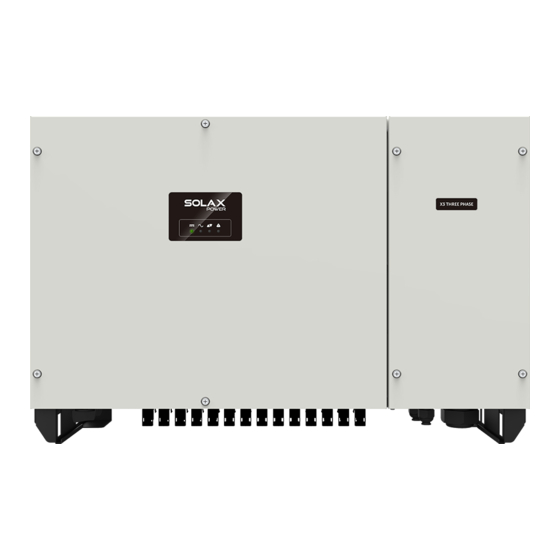
2 3 Outline and Dimensions 2 3 1 Outline Figures 2 4 to 2 6 show the outline of the inverters as follows 1 PV Indicator 2 Grid Indicator 3 COM Indicator 4 Warning Indicator Figure 2 4 The front view and amplification effect of LED indicator area Reserved for installing rear panel Figure 2 5 The rear view of this series inverter 36K/60K... -
Page 12: 3 2 Dimensions
2 3 2 Dimensions Figures 2 7 shows the dimensions of these series inverters as follows Figures 2 7 The dimensions of this series unit mm... -
Page 13: 4 Working Modes
2 4 Working Modes Three working modes of the inverter are shown as follows standby operating and shutdown Table 2 1 shows the conditions for the inverter to switch between working modes Modes Description The PV inverter enters the standby mode when >... -
Page 14: Storage
3 Storage This chapter describes the storage requirements for the inverter. The following storage instructions apply if the PV inverter will not be deployed immediately: > Do not unpack the inverter (put desiccant in the original box if the PV inverter is unpacked) >... -
Page 15: Installation
4 Installation Do not install the inverter on flammable building materials or in an DANGER area that stores flammable or explosive materials. Do not install the inverter in a place where personnel are likely to CAUTION come into contact with its enclosure and heat sinks to avoid electrical shock/burn. -
Page 16: 2 Moving The Inverter
4 2 Moving the Inverter After checking the outer packing move the PV inverter to the designated installation position horizontally Hold the handles on both sides of the inverter as shown in Figure 4 2 Figure 4 2 Moving the inverter The inverter is relatively heavy! To prevent device damage and personal CAUTION injury arrange two people to move the inverter and handle with care... -
Page 17: 3 Identify The Pv Inverter
4 3 Identify the PV Inverter 4 3 1 Nameplate After moving the PV inverter from packing box identify it by reading its nameplate labeled on the side of the inverter The nameplate contains important product information the model information communications technical specifications and compliance symbols 4 3 2 Compliance and Safety Symbols Safety symbol Description... -
Page 18: 4 Installation Requirements
4 4 Installation Requirements According to installation position two kinds of physical installation are described below in detail Support-mounting & wall-mounting 4 4 1 Determining the Installation Position Basic Requirements The inverter is protected to IP65 and can be installed indoors or outdoors The installation method and position must be appropriate for the weight and dimensions of the inverter. - Page 19 Carrier Requirements The carrier where the inverter is installed must be fire-proof Do not install the inverter on flammable building materials. The wall must be solid enough to bear the weight of the inverter Do not install the inverter on a wall made of gypsum boards or similar materials with weak sound insulation to avoid noise disturbance in a residential area.
-
Page 20: 4 2 Installation Mode Requirements
4 4 2 Installation Mode Requirements Install the inverter upright or at a maximum back tilt of 15 degrees to facilitate heat dissipation. Below are some correct / wrong installation modes as shown in Figures 4 7&4 8 The correct installation mode upright back tilt Figures 4 7 The correct installation mode... -
Page 21: 5 Support Mounting The Inverter
4 5 Support-mounting the Inverter Step 1 Move out the rear panel from the packing case and determine the positions for the inverter and the support shown as in Figure 4 9 Figure 4 9 The rear panel unit mm Step 2 Tighten the rear panel with the support using M12 bolt to a torque of 42 N m (as shown in Figure 4 10) Figure 4 10 Tightening the rear panel with the support... -
Page 22: 6 Installation Self Check
4 6 Installation Self-check Ensure that the three supporting points (on the rear side of the inverter) align with the three holes of the support; Ensure that the inverter is well fixed Ensure that the inverter in locked on the support and an antitheft lock is installed... -
Page 23: Electrical Connections
5 Electrical Connections Before performing any electrical connections, ensure that both DC and AC Switches are OFF. Otherwise, fatal injury can occur due to DANGER the high voltage caused from AC and DC cables. Grounding the PV Strings needs below prerequisites: CAUTION An isolation transformer must be installed on the AC side of each inverter;... -
Page 24: 1 Connecting Protection Ground Pgnd Cables . ( )
5.1 Connecting Protection Ground (PGND) Cables 5.1.1 Preparation The ground cable and OT terminals have been prepared with below requirements. a. Ground cable: Outdoor multi-core special cables are recommended. b. OT terminal: OT terminals OT 35~50-6. Key parameter Product series code Terminal product series code Good grounding for the inverter helps resist the impact of surge voltage and improve the EMI performance. - Page 25 Step 2 Insert the exposed core wires into the crimping areas of the OT terminal and crimp them using hydraulic pliers, as shown in Figure 5.2. Figure 5.2 Crimping a cable (unit: mm) Step 3 Remove the ground screws from the ground points, secure the PGND cable (done by step 1 &...
-
Page 26: 2 Connecting Ac Output Cables
5.2 Connecting AC Output Cables 5 2 1 Preparation The AC power cable and AC terminals have been prepared with below requirements. a AC power cable Outdoor multi copper cores cables are recommended Table 5 1 describes the specifications. Cross sectional Recommended Cable type Area of single... -
Page 27: 2 2 Procedure Of Connecting Ac Cables
5 2 2 Procedure of Connecting AC Cables AC wiring chamber on the right side of the inverter and before AC wiring remove these four retaining screws uninstall Earth wire and remove the cover of AC wiring chamber Please follow below steps to ensure equipment and personal safety. -
Page 28: 3 Connecting The Pv Strings
For operation convince and safety the inverter requires multi-stranded wire and crimping terminals with a proper crimping tool before wiring. NOTICE To avoid potential risk 125A / 400VAC overcurrent protection device is recommend to add on the output terminal. 5 3 Connecting the PV Strings PV Strings connection needs below prerequisites otherwise an DANGER electrical shock can occur. -
Page 29: 3 1 Preparation
5 3 1 Preparation PV Strings DC input cable and connectors have been prepared refer to No of DC input terminals at the bottom of inverter shown in below figure 30K/50K with 10 routes and 36K/60K with 12 routes if quantity of PV strings is less than number of input on inverter you can refer to below Table for the installation of PV strings and the inverter. - Page 30 Connectors of PV Strings: Positive and negative DC input connectors are used, as shown in Figure 5.6 and Figure 5.7. the insulation layer locking nut the insulation layer locking nut Figure 5.6 Positive connector compositions Figure 5.7 Negative connector compositions Positive and negative metal connectors are packed with positive and NOTE negative connectors respectively when shipped out.
- Page 31 Step 2 Insert the exposed areas of the positive and negative power cables into the metal terminals of the positive and negative connectors respectively and crimp them using a crimping tool, as shown in Figure 5.9. Figure 5.9 Crimping a metal connector Step 3 Insert the crimped positive and negative power cables into the corresponding positive and negative connectors until a "click"...
- Page 32 800 00 RANGE MAXMIN Hz % h FE FUSED FUSED Figure 5 12 Checking the voltage of every route Strings Step 6 Insert the positive and negative connectors into their corresponding terminals of the " " inverter until a click sound is heard as shown in Figure 5 13 Figure 5 13 Connecting to the inverter Step 7 After connecting the PV strings ensure that all connectors are in position by checking for resistance when a slight pull is applied.
-
Page 33: 4 Connecting Communication Cables
5 4 Connecting Communications Cables 5 4 1 Communications Mode Description You can use the following communications modes to implement communications Bluetooth WIFI GPRS and RS485 all of which are described as follows Bluetooth Module You can turn on the Bluetooth function of the mobile phone, and set parameters and monitor data of the inverter through the mobile APP. - Page 34 RS485 communications mode for single inverter When RS485 communications mode is applied to monitor the inverter there are two ways for connecting to the inverter connecting to single inverter and to multiple inverters Figure 5 14 demonstrates connection to single inverter to implement RS485 communications. Inverter Data Logger Router Modem...
-
Page 35: 4 2 Connecting Rs485 Communication Cables
5 4 2 Connecting RS485 Communication Cables The inverter case right side is located interface of RS485 communication cable as shown in Figure 5 16 Figure 5 16 Interface of RS485 communication cable Step 1 Remove the wiring chamber on the right of inverter, and loosen the locking cap on 485 waterproof cable connector from the bottom of inverter. -
Page 36: 4 3 Setting Rs485 Communication Address
5 4 3 Setting RS485 Communication Address Step 1 Input the company’s website in your mobile phone browser and click APP to Download the APP which is also available by scanning the QR code And then login the APP and register an account for your inverter. Step 2 Click the Extension key and select Setting in the prompt manual as shown in Figure 5 17 SEBLE-SE History... -
Page 37: 5 Power Limit
5 5 Power limit 5 5 1 Wiring diagram PV strings low-voltage power grid Load Inverter RS485 CHINT DTSU666 Figure 5 20 Wiring diagram 5 5 2 Settings via APP Power Limit Power Limit Power limit function Power limit function Disable Digital Power Meter Power limit mode... - Page 38 - Power limit function set to “Digital Power Meter” - Set the Digital Power Meter Type - Set the meter position base on the meter installed on load or on grid - Set maximum feed-in grid power if needed -“Power limit CT ratio” only for single phase inverter When Power limit function sets to “Digital Power Meter”, the RS485 of inverter will change to a Host that will communicate with digital meter using Modbus-RTU protocol with 9600 BPS, 8 data bit, 1 stop bit, no parity data format, with communication address 1.
-
Page 39: 6 Drm
5 6 DRM Inverter is provided to support DRM0 mode via V1000+. When DRM0 is connected to the Gen, the remote off mode will be automatically triggered. 0 5 6 7 G remote off DRM0 mode Figure 5 23 The V1000+ provides a simple and cost-effective solution to achieve NOTE datalogger and powerlimiter. -
Page 40: System Operation
6 System Operation 6 1 R the Inverter Start inverter after checking all below steps: 1) Check that device is fixed well on the wall. Make sure all the DC breakers and AC breakers are disconnected. ) 3 AC cable is connected to grid correctly. ) 4 All PV panels are connected to inverter correctly, DC connectors which are not used should be sealed by cover. -
Page 41: User Interface
7 User Interface Inverter operation status can be obtained from observing LED indicator status. For more details, refer to Table 7.1 LED Indicator status. 1 PV indicator 2 Grid indicator 3 COM indicator 4 Warning indicator LED indicator Status Description Voltage of PV strings meet the conditions for feed-in operation. - Page 42 View and Set Inverter running data Setting power quality response modes please refer to APP User Manual Figure 7.1 Setting power quality response modes The inverter operation data can be obtained from APP mobile phone APP downloaded through Bluetooth communication For more details refer to APP User Manual Warning Grid Warning...
- Page 43 Strings abnormal Inverter over temperature Fan abnormal Insulation resistance abnormal Leakage current abnormal Strings reverse Control power abnormal DC bias current abnormal Inverter relay abnormal Leakage current HCT abnormal System fault DC link voltage unbalance DC link over voltage Internal Communications Fault Software version incompatibility EEPROM fault Sampling inconsistency...
-
Page 44: Maintenance
8 Maintenance Before maintaining and commissioning inverter and its peripheral WARNING distribution unit switch off all the charged terminals of the inverter and wait at least 10 minutes after the inverter is powered off. 8 1 Routine Maintenance Maintain Maintenance Check Item Check Content content... -
Page 45: 2 The Inverter Troubleshooting
8 2 The Inverter Troubleshooting When inverter enters in shutdown mode abnormally the alarm light is illuminated Table 8 2 describes the troubleshooting measures for common fault alarms in the inverter. Alarm Name Causes Measures Recommended 1 If the alarm occurs accidentally possibly the Grid power grid is abnormal accidentally No extra Over Voltage... - Page 46 The insulation resistance against the ground at the 1 If the alarm occurs accidentally possibly the external input side circuits are abnormal accidentally The inverter Residual decreases automatically recovers to the normal operating status Current during the inverter after the fault is rectified. Abnormal operation which 2 If the alarm occurs repeatedly or lasts a long time...
- Page 47 remote monitor If modem or other data logger is used please reboot Communications displays zero it if still does not work after rebooting contact your outage power generation dealer. remote monitor Output switch Check if DC switch is damaged and if not switch it to displays no output tripping ON If it still doesn’t work contact your dealer...
-
Page 48: 3 Removing The Inverter
8 3 Removing the Inverter Perform the following procedures to remove the inverter: Step 1: Disconnect all cables from the inverter including communications cables DC input power cables AC output power cables and PGND cables as shown in Figure 8 1 Figure 8 1 Removing DC input connector Notes: When removing DC input connector insert the removal wrench to the bayonet press the... - Page 49 Fan Maintenance Outer fans are provided to cool the inverter check periodically and ensure that air inlets and outlets of fans are free from dust and blockage check whether the ambient temperature of the inverter exceeds the upper limit If yes improve ventilation to decrease the temperature If there is any abnormal noise emitted from the fan replace the relevant parts timely In-built PV FUSE are equipped in the inverter if any warning display that the FUSE is melt disconnect AC breaker and switch the DC switch to OFF pull out all DC input strings wait at...
-
Page 50: Quality Guarantee
9 Quality Guarantee 9 1 Quality Terms 1 Where otherwise agreed to in a contract quality warranty period of the inverter is 60 months 2 As for the PV inverter which is defective or damaged within its quality warranty period our company shall repair or replace it for free. -
Page 51: Disposal Of The Inverter
10 Disposal of the Inverter The PV inverter and its packing case are made from environment-friendly materials If the inverter service life has expired do NOT discard it with household garbage dispose the inverter in accordance with local environmental laws and regulations. -
Page 52: Technical Specifications
11 Technical Specifications Model X3-30K-LV X3-36K-LV Efficiency Max. Efficiency 97.4% Input(PV) Max. Input Voltage 800V Rated Input Voltage 360V Max. Input Current 130A (39A/39A/26A/26A) 156A (39A/39A/39A/39A) Max.Short Circuit Current 150A (45A/45A/30A/30A) 180A (45A/45A/45A/45A) Start Input Voltage/ Min. Operating Voltage 250V/200V MPPT Operating Voltage Range 200V-750V MPPT Operating Voltage Range (Full-Load) - Page 53 General Topology Transformerless IP Rating IP65 Night Self Consumption <1W Cooling Fan cooling Operating Temperature Range -25 -60 Relative Humidity Range 0-100% Max. Operating Altitude 4000m Noise <62dB Dimensions (W*H*D) 855*500*275mm Weight 73Kg 74Kg HMI & COM Display Wireless & APP +LED Communication RS485,WiFi(Optional), GPRS(Optional) Warranty...
- Page 54 Model X3-50K-TL X3-60K-TL Efficiency Max. Efficiency 98.3% 98.3% European Efficiency 98.0% 98.0% Input(PV) Max. Input Voltage 1100V Max. PV configuration 150% Rated Input Voltage 620V Max. Input Current 130A (39A/39A/26A/26A) 156A (39A/39A/39A/39A) Max.Short Circuit Current 150A (45A/45A/30A/30A) 180A (45A/45A/45A/45A) Start Input Voltage 250V MPPT Operating Voltage Range 200V-1000V...
- Page 55 General Topology Transformerless IP Rating IP65 Night Self Consumption <1W Cooling Fan cooling Operating Temperature Range -25 -60 Relative Humidity Range 0-100% Max. Operating Altitude 4000m Noise <62dB Dimensions (W*H*D) 855*500*275mm Weight 73Kg 74Kg HMI & COM Display Wireless & APP +LED Communication RS485/ WiFi , GPRS/4G/LAN(Optional) Certification...
- Page 56 Solax Power Network Technology(Zhe jiang) Co.,Ltd. No.288 Shizhu Road, Tonglu Economic Development Zone, Dongxing District, Tonglu City, Zhejiang Province, China. Tel: +86 571 5626 0011 info@solaxpower.com E-mail: 614-30166-03...
Need help?
Do you have a question about the X3-Series and is the answer not in the manual?
Questions and answers