Advertisement
Quick Links
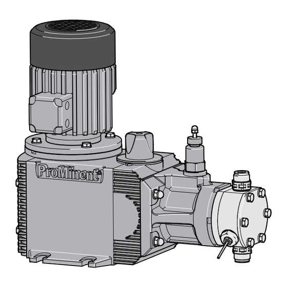
Operating instructions
Metering pumps
HYDRO/ 1 HA1a
EN
P_HY_0004_SW
Target group: trained, qualified personnel
Please carefully read these operating instructions before use. · Do not discard.
The operator shall be liable for any damage caused by installation or operating errors.
The latest version of the operating instructions are available on our homepage.
Part number: 990117
Original operating instructions (2006/42/EC)
Version: BA HY 024 01/23 EN
Advertisement

Related Manuals for ProMinent HYDRO/ 1 HA1a


Summary of Contents for ProMinent HYDRO/ 1 HA1a
- Page 1 Operating instructions Metering pumps HYDRO/ 1 HA1a P_HY_0004_SW Target group: trained, qualified personnel Please carefully read these operating instructions before use. · Do not discard. The operator shall be liable for any damage caused by installation or operating errors. The latest version of the operating instructions are available on our homepage.
- Page 2 Supplemental directives General non-discriminatory approach In order to make it easier to read, this document uses the male form in grammatical structures but with an implied neutral sense. The document is always aimed equally at women, men and gender-neutral persons. We kindly ask readers for their understanding in this simplification of the text.
- Page 3 Table of contents Table of contents Functional description..............5 1.1 Power end................5 1.2 Liquid end................6 1.3 Diaphragm monitor..............6 1.4 Overview of equipment / control elements......7 1.5 Nameplate data............... 9 1.6 ATEX nameplate data............. 9 Identity code.................. 10 Safety chapter................
- Page 4 Table of contents Performance data................43 11.1 Performance data, 50 Hz............ 43 11.2 Performance data, 60 Hz............ 44 Technical data................45 12.1 Metering reproducibility............45 12.2 Viscosity................45 12.3 Weight................. 45 12.4 Wetted materials..............45 12.5 Ambient conditions.............. 46 12.5.1 Temperatures..............46 12.5.2 Air humidity..............
- Page 5 Functional description Functional description 1.1 Power end The product range is a motor-driven metering pump with hydraulically operated multi-layer diaphragm (6). The motor moves the hydraulic piston (4) to the front by means of a worm gear and cam (1). The hydraulic piston is connected positively to the cam by a bracket (7) so that the discharge stroke as well as the suction stroke are performed by the force of the motor (so-called “Full Motion Drive”).
- Page 6 Functional description 1.2 Liquid end P_HY_0008_SW Fig. 2: Cross-section through the liquid end The heart of the liquid end is a PTFE multi-layer diaphragm (1). The PTFE multi-layer diaphragm hermetically seals the delivery chamber of the dosing head and causes displacement in the dosing head at each pump stroke.
- Page 7 Functional description 1.4 Overview of equipment / control elements P_HY_0080_SW Fig. 4: Hydro HA, Simplex (vertical) and Simplex double head Power end Oil inspection window Hydraulic end Gearbox vent stopper Liquid end Oil drain stopper Stroke adjustment dial Oil drainage plug Safety relief valve + bleed valve Diaphragm monitor Every power end includes all these components –...
- Page 8 Functional description P_HY_0084_SW 40481076 Fig. 6: Hydro HA, Triplex; a) View from left, b) View from right, c) Overall view Power end Oil inspection window Hydraulic end Gearbox vent stopper Liquid end Oil drain stopper Stroke adjustment dial Oil drainage plug Safety relief valve + bleed valve Diaphragm monitor Every power end includes all these components –...
- Page 9 026 bar Temp. -20 ... +40 °C Stroke rate 028 bar 150 rpm ProMinent GmbH, Im Schuhmachergewann 5 - 11 69123 Heidelberg, Germany P_HY_0077_SW Fig. 8: Nameplate data (example), explanation Type Identity code, see above p rtd Maximum pressure, as ordered...
- Page 10 Identity code Identity code HA1a // HYDRO API 1 - version A Drive type Simplex (vertical) Simplex double head Duplex Triplex Piston Piston Ø9 Piston Ø12 Stroke rate 50 Hz operation 60 Hz operation 50 strokes/min; 50 Hz 059 59 strokes/min; 60 Hz 60 strokes/min;...
- Page 11 Identity code HA1a // HYDRO API 1 - version A Drive type 3-phase, 265/460 V, 60 Hz, 0.37 kW (Exde) T4 Speed stroke control motor 3-phase 230/400 V controllable motor with integrated frequency con‐ verter without motor, with 160/71 flange without motor, with NEMA flange without motor, with 160/71 ATEX flange without motor, with NEMA ATEX flange...
- Page 12 Identity code HA1a // HYDRO API 1 - version A Drive type CE + UKCA CE + UKCA + ATEX Documentation* German English French Spanish Russian modified Unit of measure‐ ment bar, l/h psi, gph kPa, l/h * Other languages on request...
- Page 13 Safety chapter Safety chapter 3.1 Labelling of Warning Information Introduction These operating instructions provide information on the technical data and functions of the product. These operating instructions provide detailed warning information and are provided as clear step-by-step instructions. The warning information and notes are categorised according to the fol‐ lowing scheme.
- Page 14 Safety chapter 3.2 User qualification WARNING! Danger of injury with inadequately qualified personnel The operator of the system / equipment is responsible for ensuring that the qualifications are fulfilled. If inadequately qualified personnel work on the unit or loiter in the hazard zone of the unit, this could result in dangers that could cause serious injuries and material damage.
- Page 15 We recommend the installation of a protective canopy. Observe the general limitations with regard to viscosity limits, chem‐ ical resistance and density - see also the ProMinent Resistance List, product catalogue or at www.prominent.com. Only suitable pumps may be used in areas at risk from explosion.
- Page 16 – Take into account the resistance of the wetted mate‐ rials and the ProMinent Resistance List when selecting the feed chemical - see the ProMinent Product Catalogue or visit ProMinent. INFORMATION: Refer to the documentation for the bought-in parts. Installation height The standard version is intended for installation up to a height of 1,000 m above sea level.
- Page 17 Safety chapter WARNING! The inside of the dosing head needs to be constantly filled with medium in normal mode, and the start-up and run-down processes have to be designed in such a way by the operator so that no explosive mixture is produced inside the dosing head.
- Page 18 Storage, transport and unpacking Storage, transport and unpacking User qualification: instructed user Ä Chapter 3.2 ‘User qualification’ on page 14 Use lifting points with suitable lifting means. Secure the pump to prevent it from falling. Oil can escape by improper storage or transportation. Only transport the unit with the sealing screw , and not the vent screw, fitted to the oil filler neck.
- Page 19 Assembly Assembly User qualification: trained qualified personnel Ä Chapter 3.2 ‘User qualification’ on page 14 Compare the dimensions on the dimensional drawing with those of the pump. Assembly of the motor - with designs without motor WARNING! The following instructions relevant in areas at risk from explosion apply in areas at risk from explosion.
- Page 20 Assembly Motor number: “1”; “3”; “4”; “6” The motor number identifies the motor. B1272 Fig. 11: Situation in the flange with claw coupling (arrow) without motor P_HY_0060_SW Fig. 12: Approximate height (Q) of the coupling claw on the motor shaft Tab.
- Page 21 Assembly 5.2 Space requirement Motor may overheat The motor may overheat if the necessary supply of cooling air is not guaranteed. Maintain sufficient clearance between the air intake opening and the walls. The distance should be greater than 1/4 of the diameter of the air intake opening.
- Page 22 Installation Installation 6.1 Installation, hydraulic User qualification: trained qualified personnel Ä Chapter 3.2 ‘User qualification’ on page 14 WARNING! Danger from hazardous substances! Possible consequence: Fatal or very serious injuries. Please ensure when handling hazardous substances that you have read the latest safety data sheets provided by the manufacture of the hazardous substance.
- Page 23 Installation Pipework forces F and torque M P_HY_0076_SW Fig. 17: Alignment of pipework forces F and torque M Tab. 4: The maximum loads at the discharge and suction connector for material versions S1 and H1 (SS and HC) are as follows: Screw connector Flange connection...
- Page 24 Installation 6.1.1 Basic installation notes Examples P_MOZ_0043_SW Fig. 18: (A) standard installation, (B) with pulsation damper Main line Storage tank Tab. 5: Legend for hydraulic diagram Symbol Explanation Symbol Explanation Metering pump Foot valve with filter mesh Injection valve Level switch Back pressure valve or safety valve Manometer 6.2 Installation, electrical...
- Page 25 Installation Motor WARNING! Only motors with a frequency converter: Danger of elec‐ tric shock – The danger of an electric shock remains for 3 minutes after the supply voltage has been switched off on conducting parts of the motor with integrated frequency converter and on the lines themselves.
- Page 26 Installation Diaphragm monitoring sensor (optional) a) Diaphragm monitoring sensor with switch contact The poles of the cable can be connected as required. b) NAMUR sensor, inherently safe Make sure that the monitoring/feed equipment installed by the cus‐ tomer is capable of evaluating the current variations of the Namur sensor to indicate a diaphragm rupture.
- Page 27 Start up and operation Start up and operation User qualification: trained qualified personnel Ä Chapter 3.2 ‘User qualification’ on page 14 WARNING! Danger from hazardous substances! Possible consequence: Fatal or very serious injuries. Please ensure when handling hazardous substances that you have read the latest safety data sheets provided by the manufacture of the hazardous substance.
- Page 28 Dismantle the section of hose. Fit the discharge line. 7.2 Calibrate the stroke control drive (optional) The stroke control drive is calibrated to the capacity ordered ex-factory. Please contact ProMinent if you wish the stroke control drive to be cali‐ brated to another capacity.
- Page 29 Maintenance Maintenance User qualification: trained and qualified personnel, unless otherwise stated Ä Chapter 3.2 ‘User qualification’ on page 14 WARNING! Danger from hazardous substances! Possible consequence: Fatal or very serious injuries. Please ensure when handling hazardous substances that you have read the latest safety data sheets provided by the manufacture of the hazardous substance.
- Page 30 When changing the hydraulic oil, pay attention to wear on the worm Instructed person ating hours 1 x per year gear. Have the drive repaired by ProMinent in the event of increased wear. Change hydraulic oil, see “Changing hydraulic oil” in this chapter.
- Page 31 Maintenance 8.3 Changing the hydraulic oil Draining the hydraulic oil Combined oil The hydraulic oil is a combined oil, which is responsible for transfer of the hydraulic force, as well as for lubricating the gear. The hydraulic oil can become hot when the pump is exposed to extensive loading.
- Page 32 Maintenance Slowly fill hydraulic oil through the opening for the gearbox vent stopper (3) until the oil inspection window (6) is 1/3 covered. Start up the pump. Allow the pump to run for 1 ... 2 minutes. Top up hydraulic oil if necessary. Screw the gearbox vent stopper (3) back in, but do not close the vent valve.
- Page 33 Maintenance Slide into the valve body (1) one after another: 1 seal (2) and 1 valve seat (3). Pay attention to the direction. 1 seal (2) and 1 valve bushing (4). If fitted: Slide 1 spring (*) into the spring guide of the valve seat (3).
- Page 34 Maintenance 8.5.3 Replacing the diaphragm Fig. 22: Diaphragm Depressurise the suction and pressure lines. Is the hydraulic oil drained? Unscrew the suction and pressure lines from the liquid end. Remove the liquid end with the dosing head screws from the hydraulic end.
- Page 35 Maintenance P_HY_0009_SW Fig. 23: Wetted areas (grey shaded) 8.5.4 Tightening torque for screws Dosing head material 1st stage 2nd stage 6 Nm 12 Nm 6 Nm 12 Nm 8 Nm 20 Nm 8 Nm 20 Nm 8.5.5 Filling hydraulic oil into the hydraulic end Perform the following work identically on both dosing heads with double head versions.
- Page 36 Maintenance Screw in the new safety relief valve (tightening torque - 15 Nm). Mark the collar of the safety relief valve with sealing paint. 8.7 Repairing the diaphragm monitoring sensor Visual display B1316 Fig. 24: Visual display Regularly clean the display.
- Page 37 Maintenance 30 V-version Checking the diaphragm monitoring When changing the diaphragm, unscrew the diaphragm monitoring sensor sensor from the dosing head. Check for electrical continuity: Using a blunt insulating probe (Ø 2 ... 3 mm, no sharp edges), press into the channel of the diaphragm monitoring sensor. ð...
- Page 38 Maintenance ATEX version Checking the diaphragm monitoring When changing the diaphragm, unscrew the diaphragm monitoring sensor sensor from the dosing head. Check that the monitor does not indicate Using a blunt insulating probe (Ø 2 ... 3 mm, no sharp edges), press any diaphragm damage: into the channel of the diaphragm monitoring sensor.
- Page 39 Maintenance 8.8 Calibrating the dosing rate The pump is calibrated to the pressure stage stipulated in the identity code. Tab. 6: The following pressure stages (in bar) are available: Pump INFORMATION: The dosing rate can only be calibrated when the pressure line is connected and under normal operating conditions.
- Page 40 Troubleshooting Troubleshooting User qualification: trained and qualified personnel / elec‐ trical technician Ä Chapter 3.2 ‘User qualification’ on page 14 Fault Cause Solution Pump does not reach high pressures The valves are dirty or worn. Repair the valves - see “Repair” or does not prime despite full stroke chapter.
- Page 41 Troubleshooting Fault Cause Solution The power end motor is very hot. The pressure line is seriously con‐ Remove any constriction of the stricted. pressure line. Have the safety relief valve checked. All other faults. Other causes. Call ProMinent Service.
- Page 42 Decommissioning and disposal Decommissioning and disposal User qualification: trained and qualified personnel / elec‐ trical technician Ä Chapter 3.2 ‘User qualification’ on page 14 WARNING! Danger from hazardous substances! Possible consequence: Fatal or very serious injuries. Please ensure when handling hazardous substances that you have read the latest safety data sheets provided by the manufacture of the hazardous substance.
- Page 43 Performance data Performance data Piston Ø 9 and 12, version with double ball valves When pumps are selected in accordance with API 675 (control range 1:10), the permitted rated flow configuration is possible in the stated range. The litre capacity indicated with [...] is the maximum litre capacity with an applicable control range of 1:5 and so does not comply with API 675.
- Page 44 Performance data 11.2 Performance data, 60 Hz Piston Ø Pressure Pump capacity in l/h at strokes / min (60 Hz) Q min. - Stroke Suction Suction / Shipping Q max. volume lift pressure weight (theor.) side con‐ nector m water G-DN stroke column...
- Page 45 Technical data Technical data Only with “M - modified” version: INFORMATION: Please observe the “Supplementary information for modi‐ fied version” at the end of the chapter. The supplementary information replaces and supplements the technical data. 12.1 Metering reproducibility Reproducibility of ± 1% with measurements taken under constant condi‐ tions, minimum 10% stroke length and water at 20 °C, when installed cor‐...
- Page 46 Technical data 12.5 Ambient conditions 12.5.1 Temperatures Tab. 7: Pump, complete Specification Value in °C Storage and transport temperature: -25 ... +60 Ambient temperature in operation (“Standard” version, for drive): -10 ... +40 Ambient temperature in operation (“Low temperature” version, for drive): -25 ...
- Page 47 Technical data 12.5.3 Installation height Specification Value in metres above sea level Maximum installation height *: 1000 * with standard pumps: Fit at higher installation heights at your own risk. with ATEX pumps: We advise that you contact a specialist for ATEX motors with higher installation heights. 12.6 Housing degree of protection Protection against contact and moisture according to EN IEC 60529 is IP...
- Page 48 Technical data Contact (standard) Tab. 15: Contact loading, max. at voltage Maximum current 30 V DC The contact is an opener. The contact is an potential-free. For safety reasons we recommend connecting to a – protective low voltage, e.g. in accordance with EN 60335-1 (SELV ).
- Page 49 Technical data Namur sensor (Specified for EX zones) 5–25 V DC, in accordance with Namur or DIN 60947-5-6, potential-free design. Specification Value Nominal voltage * 8 V DC Power consumption - active surface uncovered > 3 mA Power consumption - active surface covered <...
- Page 50 Technical data Manufacturer Name Viscosity class Order no. for 1 litre Food Mobil SHC Cibus 1007664 or comparative hydraulic oil 12.12 Sound pressure level Sound pressure level Sound pressure level LpA < 70 dB according to EN ISO 20361 at maximum stroke length, maximum stroke rate, maximum back pressure (water) 12.13 Supplement for modified versions (With Identcode specification "Version": "M"...
- Page 51 Dimensional drawings Dimensional drawings 13.1 Dimensional drawing of the HYDRO HA1a 40547182 A3666 Fig. 28: Dimensional drawing of the HYDRO/ 1 API 675. All values are in millimetres.
- Page 52 Dimensional drawings 13.2 Dimensional drawing of the HYDRO HA1a, double head version 40547182 A3667 Fig. 29: Dimensional drawing of the HYDRO HA1a, double head version, for dimensions A and K refer to the table in Ä Further information on page 51...
- Page 53 Dimensional drawings 13.3 Dimensional drawing of the HYDRO HA1a with add-on power end 40547182 A3668 Fig. 30: Dimensional drawing of the HYDRO HA1a with add-on power end, for dimensions A and K refer to the table in Ä Further information on page 51...
- Page 54 Dimensional drawings 13.4 Dimensional drawing of the HYDRO Ha1a, Triplex 40547182 A3669 Fig. 31: Dimensional drawing of the HYDRO HA1a, Triplex, for dimensions A and K see the table in Ä Further informa‐ tion on page 51...
- Page 55 Dimensional drawings 13.5 Motor flange HA1a P_HY_0069_SW 61_02-101_00_17-73. Fig. 32: Motor flange HA1a 13.6 HA1a double head version with actuator, base and connecting flanges P_HY_0071_SW 61_02-101_00_19-73 Fig. 33: HA1a double head version with actuator, base and connecting flanges...
- Page 56 Ordering information Ordering information 14.1 Exploded view P_HY_0017_SW Fig. 34: Exploded view of the HYDRO liquid end. Numbered positions = scope of delivery of the PVT spare parts kit. Technical changes reserved. Seals (set) Valve balls Pressure connector, complete Suction connector, complete Diaphragm Reinforce plate, only with PVT 14.2...
- Page 57 Ordering information 14.3 Diaphragms PTFE metering diaphragm for liquid end Pump type Order no. FMH 25 100010, 100009, 100007, 100006, 100003 1005545 064025, 064022, 064018, 064015, 064007 FMH 60 025068, 025060, 025048, 025040, 025019 1005546 Diaphragm PTFE / Hastelloy C, coated for liquid end Pump type Order no.
- Page 58 Ordering information Seal Spare part Order no. Seal for the oil drainage stopper 1004803...
- Page 59 EN 50581:2012 Only start up the pump when it has been established that the machine into which the pump has been installed com‐ plies with the provisions of the Machine Directive. Place/Date: Heidelberg 29.10.2021 Download the Declaration of Incorporation at www.prominent.com.
- Page 60 Only start up the pump when it has been established that the machine into which the pump has been installed com‐ plies with the provisions of the Machine Directive. Place/Date: Heidelberg 29.10.2021 Download the Declaration of Incorporation at www.prominent.com. 15.3 EU Declaration of Conformity for Machinery In accordance with DIRECTIVE 2006/42/EC OF THE EUROPEAN PAR‐...
- Page 61 EN ISO 12100:2010, particular: EN 809:1998+A1:2009+AC:2010, EN 61000-6-2:2005, EN 61000-6-4:2007+A1:2011, EN 60204-1:2018, EN IEC 63000:2018. Representative commissioned to Dr. Patrick Machauer compile the technical documents: Im Schuhmachergewann 5-11 D 69123 Heidelberg, Germany Place/Date: Heidelberg 29.10.2021 Download the Declaration of Conformity at www.prominent.com.
- Page 62 Only start up the pump when it has been established that the machine into which the pump has been installed com‐ plies with the provisions of the Machine Directive. Place/Date: Heidelberg 29.10.2021 Download the Declaration of Incorporation at www.prominent.com. 15.5 EU Declaration of Conformity for Machinery In accordance with DIRECTIVE 2006/42/EC OF THE EUROPEAN PAR‐...
- Page 63 EN ISO 12100:2010, particular: EN 809:1998 + A1:2009 + AC:2010, EN IEC 63000:2018 Representative commissioned to Dr. Patrick Machauer compile the technical documents: Im Schuhmachergewann 5-11 D 69123 Heidelberg, Germany Place/Date: Heidelberg 29.10.2021 Download the Declaration of Conformity at www.prominent.com.
- Page 64 EN ISO 12100:2010, particular: EN 809:1998+A1:2009+AC:2010, EN IEC 63000:2018 Persons commissioned to compile ProMinent Fluid Controls (UK) Ltd the technical documents: Resolution Rd, Ashby de la Zouch Leicestershire, LE65 1DW United Kingdom Place/Date: Heidelberg 29.10.2021 Download the Declaration of Conformity at www.prominent.com.
- Page 65 II 2G Ex h IIC T4 Gb X for %% = “1P” II 2G Ex h IIB T4 Gb X for %% = “2P” or “3P” X: max. medium temperature 90 °C Assess the ignition risk when assembling. Place/Date: Heidelberg 29.10.2021 Download the Declaration of Incorporation at www.prominent.com.
- Page 66 X: max. medium temperature 90 °C Assess the ignition risk when assembling. Persons commissioned to compile ProMinent Fluid Controls (UK) Ltd the technical documents: Resolution Rd, Ashby de la Zouch Leicestershire, LE65 1DW United Kingdom Place/Date: Heidelberg 29.10.2021 Download the Declaration of Incorporation at www.prominent.com.
- Page 67 II 2G Ex h IIB T4 Gb X for § = “L” or “Q”, %% = “2P” or “3P” X: maximum medium temperature 90 °C Representative commissioned to Dr. Patrick Machauer compile the technical documents: Im Schuhmachergewann 5-11 D 69123 Heidelberg, Germany Place/Date: Heidelberg 29.10.2021 Download the Declaration of Conformity at www.prominent.com.
- Page 68 II 2G Ex h IIB T4 Gb X for %% = “2P” or “3P” X: max. medium temperature 90 °C Persons commissioned to compile ProMinent Fluid Controls (UK) Ltd the technical documents: Resolution Rd, Ashby de la Zouch Leicestershire, LE65 1DW United Kingdom Place/Date: Heidelberg 29.10.2021 Download the Declaration of Incorporation at www.prominent.com.
- Page 69 II 2G Ex h IIB T4 Gb X for %% = “2P” or “2P” X: maximum medium temperature 90 °C Assess the ignition risk when assembling. Representative commissioned to Dr. Patrick Machauer compile the technical documents: Im Schuhmachergewann 5-11 D 69123 Heidelberg, Germany Place/Date: Heidelberg 29.10.2021 Download the Declaration of Conformity at www.prominent.com.
- Page 70 II 2G Ex h IIB T4 Gb X for %% = “2P” or “3P” X: max. medium temperature 90 °C Persons commissioned to compile ProMinent Fluid Controls (UK) Ltd the technical documents: Resolution Rd, Ashby de la Zouch Leicestershire, LE65 1DW United Kingdom Place/Date: Heidelberg 29.10.2021 Download the Declaration of Incorporation at www.prominent.com.
- Page 71 Index Index 1, 2, 3 ... Information in the event of an emergency ..17 Installation ....... 22 ≧...
- Page 72 Index Technical data ......45, 50 Temperature monitoring ..... 47 Temperatures .
- Page 76 ProMinent GmbH Im Schuhmachergewann 5-11 69123 Heidelberg Germany Telephone: +49 6221 842-0 Fax: +49 6221 842-419 Email: info@prominent.com Internet: www.prominent.com 990117, 1, en_GB © 2023...
Need help?
Do you have a question about the HYDRO/ 1 HA1a and is the answer not in the manual?
Questions and answers