
Related Manuals for Eaton Power Xpert UX 36


Summary of Contents for Eaton Power Xpert UX 36
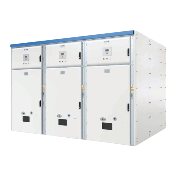
- Page 1 Effective August 2017 Power Xpert UX 36 Supersedes December 2016 User manual Power Xpert UX 36 with W-VACi circuit breaker (up to 36 kV) air insulated medium-voltage switchgear...
- Page 2 If further information is required, an Eaton sales office should be consulted. Sale of the product shown in this literature is subject to the terms and conditions outlined in appropriate Eaton selling policies or other contractual agreement between Eaton and the purchaser.
- Page 3 Floor plan drawings ...........39 USER MANUAL MN022004EN August 2017 www.eaton.com...
- Page 4 Power Xpert UX 36 USER MANUAL MN022004EN August 2017 www.eaton.com...
- Page 5 LSC2B-PM. equipment: System construction WARNING A Power Xpert UX 36 panel is constructed of sheet metal Personal (fatal) danger to personnel and bystanders. circuit breaker panels and withdrawable vacuum circuit breakers. CAUTION The main busbar system is located at the top of the panels.
- Page 6 Never take any action without knowing what effect it General instructions will have. Eaton has done its utmost to inform user as accurately ote: Read through all actions first, using the relevant and as fully as possible concerning any dangers involved figures.
- Page 7 • If the switchgear is arranged for rear cable access, then Eaton Power Xpert UX 36 switchgear can be used in areas a clear space of 1.2 m is required to the rear wall of under normal conditions as described in IEC 62271-1 the switchroom, at least 0.1 m space at one end of the...
- Page 8 Introduction Clear space for Power Xpert UX 36 switchgear with front and rear access. Figure 1. Clear space for 36 kV panel USER MANUAL MN022004EN August 2017 www.eaton.com...
- Page 9 If possible, leave extinguishing the fire to the fire brigade • Use non-conducting extinguishing materials • If necessary, use extinguishers in the area around the • installation. Never attempt to extinguish the installation itself, even if it appears to be dead USER MANUAL MN022004EN August 2017 www.eaton.com...
- Page 10 A complete product rating plate is made up of a main rating plate with supplementary rating plates if required. The main product rating plate is headed with the Eaton logo. The type of switching system, the type of panel it contains and the components used determine the complete product rating plate.
- Page 11 The panels are compartmented according to the type of function. The compartments are: I. Low-voltage compartment II. Busbar compartment III. Circuit breaker compartment IV. Cable compartment Figure 4. Circuit breaker or control unit on transport trolley Figure 3. Panel compartmenting USER MANUAL MN022004EN August 2017 www.eaton.com...
- Page 12 Besides primary cables, secondary and auxiliary cables may also be installed. 1. Earth switch 2. Spout containing fixed contact, cable side 3. Power cable 4. Current transformer 5. Cable glanding plate Figure 5. Cable connections USER MANUAL MN022004EN August 2017 www.eaton.com...
- Page 13 Current transformers Figure 6. Mimic panel Power Xpert UX 36 switchgear can be equipped with current transformers for protection, measuring, and metering. Switch position indication Current transformers are always fitted in the rear of the cable compartment or in the riser/sectionalizer panel.
- Page 14 The earthing switch can be locked with a padlock. Special locks are used in some installations, i.e., with the aid of a locking coil. Withdrawable units Power Xpert UX 36 switchgear can contain a variety Figure 9. Vacuum circuit breaker unit of switching/measuring equipment in circuit breaker compartment.
- Page 15 Panel types to provide consumers with energy, offering short-circuit protection and switching of the circuit. All Power Xpert UX 36 switchgear is constructed in modular fashion with a series of panels with different functions. Metering panel (client-specific) Each panel is made up of 4 compartments.
- Page 16 NEVER approach an unearthed installation. Ensure maintenance work is carried out timely, in accordance with the instructions in this manual. Replace worn and/or damaged parts only with original Eaton spares or spares approved by Eaton. USER MANUAL MN022004EN August 2017 www.eaton.com...
- Page 17 Table 4. Earthing switches with IEC 62271-102 Item Unit Specification Rated voltage 36 (max.) Rated short-circuit making current Rated short time withstand current kA/s 31.5/ 3 Table 5. Internal arc Item Unit Specification Internal arc kA/s 31.5/1 USER MANUAL MN022004EN August 2017 www.eaton.com...
- Page 18 Table 8. Weights Circuit-breaker panel Approximate weights including circuit breaker and current transformers 36 kV UX36 31.5 kA 1250 A 1200 mm wide 850~1850 kg UX36 31.5 kA 2500 A 1200 mm wide 850~1850 kg USER MANUAL MN022004EN August 2017 www.eaton.com...
- Page 19 The floor of the operating area should comply with the This chapter contains information on transporting and setting following: up Power Xpert UX 36 switchgear, on coupling busbar and The floor must be flat and level to within ± 2 mm per •...
- Page 20 System assembly Figure 12. Floor plan for Power Xpert UX 36 switchgear (example) USER MANUAL MN022004EN August 2017 www.eaton.com...
- Page 21 Never stand under a hoisted load • A Power Xpert UX 36 system is normally transported in 1 panel. The sections are placed onto pallets and are packed The angle of the lifting chain or strap relative to the lifting •...
- Page 22 There are many types of switchgear in the UX 1. Lift the Power Xpert UX 36 on one side and put a solid series and the dimensions of the foundation are different.
- Page 23 10. Repeat (3) above for all other panel sections in the switchgear to align and fix to the level floor. Figure 16. Location of the bolts connecting adjacent panel Figure 14. Coupling bolt assembly USER MANUAL MN022004EN August 2017 www.eaton.com...
- Page 24 1. Connect adjacent panel’s earthing busbar in the bottom part of the cable compartment. 2. Connect the earthing busbar of the Power Xpert UX 36 installation to the earth point of the switchroom. Figure 18. Bolts connection for main busbar (1250 A) 3.
- Page 25 More detailed information is found in the following section, “Connecting a main cable. ” If necessary, the cable gland plate must be provided with cable cut-outs at site. Figure 20. Connecting main cable USER MANUAL MN022004EN August 2017 www.eaton.com...
- Page 26 3. Secure the cables in the cable duct with cable clips or tie-wraps. 4. Connect the cables in accordance with the diagram pack. 5. Refit the cable duct cover. Figure 23. Inter-panel connection of auxiliary cables USER MANUAL MN022004EN August 2017 www.eaton.com...
- Page 27 For operating of the circuit breaker unit see the user manual This chapter contains the operating procedures for circuit of the W-VACi. breaker units used in Eaton Power Xpert UX 36 switchgear. 1. Secondary Connector Refer to insert the W-VACi Operations and Maintenance Manual part of the technical documentation.
- Page 28 A special hand crank is provided to rack the unit IN and OUT of the compartment. During initial insertion (INSERT position) or complete withdrawal (REMOVED position) of a unit from the panel, a lifting and transportation trolley is used. USER MANUAL MN022004EN August 2017 www.eaton.com...
- Page 29 In this position, the shutters are closed. The following three steps are always followed when inserting or withdrawing a withdrawable unit. Figure 27. Three steps for inserting / withdrawing USER MANUAL MN022004EN August 2017 www.eaton.com...
- Page 30 7 . Turn the hand crank clockwise until the unit is fully inserted. 8. Remove the hand crank. 9. The unit is now locked in the SERVICE position and is fully operational. USER MANUAL MN022004EN August 2017 www.eaton.com...
- Page 31 The maximum size of the padlock hasp is 8 mm diameter. To install the padlock, proceed as follows: 1. Withdraw the unit. 2. Check that the shutters closed properly. 3. Install the padlock as shown in the illustration. Figure 31. Padlock shutters USER MANUAL MN022004EN August 2017 www.eaton.com...
- Page 32 6. Remove the operating handle. 7 . The cover can now be closed, and if required, a padlock can be fitted on the locking catch. The earth switch is now padlocked in the ON position. USER MANUAL MN022004EN August 2017 www.eaton.com...
- Page 33 INSERT/ REMOVED position. For details, refer to “Switching off the earthing switch” above. Figure 33. Operating earth switch Figure 32. Location of the operating shaft on a standard built-in earthing switch USER MANUAL MN022004EN August 2017 www.eaton.com...
- Page 34 IEC 62271-200 standard. Eaton cannot be responsible for actions carried out after handover. Acceptance testing can be carried out in the Eaton factory or on site, in the presence of the client and/or an independent Decommissioning testing authority.
- Page 35 System commissioning and decommissioning Table 9. Materials that may be found in Power Xpert UX 36 switchgear Material Symbol Description Aluminum Plating Various metal alloys — Gear wheels, rotation discs, vacuum switches Epoxy Support and insulating bushings, tapered bushings, current and voltage...
- Page 36 1. Carry out visual inspection checking: Inspection and maintenance, general For dirt, dust and moisture • Power Xpert UX 36 switchgear and the withdrawable units Instruments and relays for faults used in the switchgear require little maintenance. • For loose or discolored wiring However, inspection and checks should be made at regular •...
- Page 37 If correction of the fault might lead to dangerous situations, all necessary steps must be taken to limit these dangers to a minimum. You should contact Eaton if work on the primary part of the installation is required. All operations must be carried out by or under the supervision of qualified persons.
- Page 38 Circuit breaker will not rack in or out of the panel, Carriage electro-mechanical interlock fitted and Connect the 58-pin socket. the racking in handle appears to be jammed. 58-pin socket not plugged in. No control voltage Apply relevant control voltage. present. USER MANUAL MN022004EN August 2017 www.eaton.com...
- Page 39 Panel door key Transport guide Optional Name 58-pole connection lead 2 m length 58-pole connection lead 1 m length Figure 34. Operating handle for earthing panel door key switch Figure 35. Operating handle for VCB USER MANUAL MN022004EN August 2017 www.eaton.com...
- Page 40 OPERATIONS MANAGER must ensure that all requirements, rules and instructions are complied with. Communication Before starting operations, the INSTALLATION MANAGER must be informed of the intended operations. See EN 50110-1 § 4.4 for additional requirements. USER MANUAL MN022004EN August 2017 www.eaton.com...
- Page 41 Witdrawable unit A unit on a withdrawable carriage designed to be inserted into the switchgear compartment and can be a circuit breaker, metering truck, disconnector truck, VT truck for example. USER MANUAL MN022004EN August 2017 www.eaton.com...
- Page 42 Data such as type, ratings, price, stock number or other • Table of contents order information • Diagram pack, including: User manuals: Single line diagram User manual for the Eaton equipment used in the • • relevant version(s) Equipment diagrams • Panel diagrams •...
- Page 43 Appendix Floor plan drawings Front view Side view Figure 36. Floor plan drawings USER MANUAL MN022004EN August 2017 www.eaton.com...
- Page 44 We make what matters work. At Eaton, we believe that power is a fundamental part of just about everything people do. Technology, transportation, energy and infrastructure—these are things the world relies on every day. That’s why Eaton is dedicated to helping our customers find new ways to manage electrical, hydraulic and mechanical power more efficiently, safely and sustainably.
Need help?
Do you have a question about the Power Xpert UX 36 and is the answer not in the manual?
Questions and answers