Advertisement
Quick Links
Advertisement

Related Manuals for Impecca IPAC05-E1


Summary of Contents for Impecca IPAC05-E1
- Page 1 Portable Air Conditioner User’s Guide MODELS: IPAC05-E1 IPAC06-E1 www.impecca.com v.1.1...
- Page 3 TABLE OF CONTENTS IMPORTANT SAFETY INSTRUCTIONS ....... .3 UNIT DIAGRAM ..........15 INSTALLATION INSTRUCTIONS .
- Page 4 IMPORTANT SAFETY INSTRUCTIONS Read Before Operating: Always read all instructions thoroughly before using the appliance. • This appliance is for household use only. • Disconnect the appliance from its power source during service and when replacing parts and cleaning. • Please note: Check the nameplate for the type of refrigerant gas used in your appliance.
- Page 5 Do not use wax, thinner, or a strong detergent. Do not use the unit in the presence of inflammable substance or vapour such as alcohol, insecticides, gasoline, etc. • If the appliance is making unusual sounds or is emitting smoke or an unusual odor, unplug it immediately.
- Page 6 WARNING • The handling, installation, storage, servicing and disposal must comply with the provisions of gas-related national laws and regulations, and also national wiring regulation. • It is necessary to clear away the refrigerant in the system when maintaining or scrapping an appliance.
- Page 7 DO NOT use the product in areas where gasoline, paint or other flammable goods and objects are used or stored This appliance is designed for indoor residential applications only. lt should not be used for commercial or industrial applications. DO NOT attempt to repair or adjust any electrical or mechanical functions of the appliance as this may cause danger and void the warranty.
- Page 8 The achieved competence should be documented by a certificate. HH.2 Information and training HH.2.1 The training should include the substance of the following: HH.2.2 Information about the explosion potential of FLAMMABLE REFRIGERANTS to show that flammables may be dangerous when handled without care. HH.2.3 Information about POTENTIAL IGNITION SOURCES, especially those that are not obvious, such as lighters, light switches, vacuum cleaners, electric heaters.
- Page 9 c) Repair • Portable equipment shall be repaired outside or in a workshop specially equipped for servicing units with FLAMMABLE REFRIGERANTS. • Ensure sufficient ventilation at the repair place. • Be aware that malfunction of the equipment may be caused by refrigerant loss and a refrigerant leak is possible.
- Page 10 the refrigerant to the outside. Take care that the drained refrigerant will not cause any danger. In doubt, one person should guard the outlet. Take special care that drained refrigerant will not float back into the building. • When flammable refrigerants are used, a) Evacuate the refrigerant circuit.
- Page 11 during which flammable refrigerant can possibly be released to the surrounding space. Prior to work taking place, the area around the equipment is to be surveyed to make sure that there are no flammable hazards or ignition risks. “No Smoking” signs shall be displayed.
- Page 12 then a permanently operating form of leak detection shall be located at the most critical point to warn of a potentially hazardous situation. 2.2 Particular attention shall be paid to the following to ensure that by working on electrical components, the casing is not altered in such a way that the level of protection is affected.
- Page 13 Leak detection fluids are also suitable for use with most refrigerants but the use of detergents containing chlorine shall be avoided as the chlorine may react with the refrigerant and corrode the copper pipe-work. NOTE Examples of leak detection fluids are –...
- Page 14 - Cylinders shall be kept upright. - Ensure that the refrigeration system is earthed prior to charging the system with refrigerant. - Label the system when charging is complete (if not already). - Extreme care shall be taken not to overfill the refrigeration system. Prior to recharging the system it shall be pressure tested with OFN.
- Page 15 RECOVERY When removing refrigerant from a system, either for servicing or decommissioning, it is recommended good practice that all refrigerants are removed safely. When transferring refrigerant into cylinders, ensure that only appropriate refrigerant recovery cylinders are employed. Ensure that the correct number of cylinders for holding the total system charge are available.All cylinders to be used are designated for the recovered refrigerant and labelled for that refrigerant (i.e.
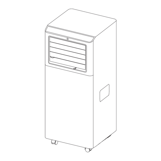
- Page 16 UNIT DIAGRAM 1. Control panel 4. Handle (both sides) 8. Intake grille 2. Remote control 5. Castors 9. Plug fixer receiver 6. Intake grille 10. Condenser drain 3. Deflector 7. Air outlet grille 11. Power cable ** Open the deflector before use the appliance. Parts Parts Name Quantity...
- Page 17 INSTALLATION INSTRUCTIONS EXHAUSTING HOT AIR When use the appliance in cool mode, the hot air exchange of the condenser must be exhausted out of the room completely. First position unit on a flat floor and make sure there's a minimum of 18" (45cm) clearance around the unit, and is within the vicinity of a single circuit outlet power source.
- Page 18 NOTE: If the window opening is less than the minimum length of the window slider kit, cut the end without the hold in it short enough to fit in the window opening. Never cut out the hole in window slider kit. WINDOW SLIDER KIT INSTALLATION 1: Parts: A.
- Page 20 DISPLAY SCREEN AND CONTROL PANEL 1. Control panel 4. Handle (both sides) 8. Intake grille 2. Remote control 5. Castors 9. Plug fixer receiver 6. Intake grille 10. Condenser drain 3. Deflector 7. Air outlet grille 11. Power cable REMOTE CONTROL Fan speed button Increase button Mode button...
- Page 21 INSERTING OR REPLACING THE BATTERIES • Remove the cover on the rear of the remote control; • Insert two "AAA" 1.5V batteries in the correct position (see instructions inside the battery compartment; NOTE: • If the remote control unit is replaced or disposed of, the batteries must be removed and discarded in accordance with current legislation as they are harmful to the environment.
- Page 22 • Press the " " button a number of times until the "Fan" symbol light appears. • Select the required fan speed by pressing the " "button to select the required fan speed: High / Low. DRY mode Ideal to reduce room humidity (spring and autumn, damp rooms rainy periods, etc). In dry mode, the appliance should be prepared in the same way as for cool mode, with the air exhaust hose attached to enable the moisture to be discharged outside.
- Page 23 The SLEEP function can be canceled at any time during operation by pressing the "Sleep", "Mode" or "fan speed" button. In DRY mode, SLEEP function is still available. SETTING THE TIMER This timer can be used to delay the appliance startup or shutdown, this avoids wasting electricity by optimising operating periods.
- Page 24 • Protect the room from direct exposure to the sun by partially closing curtains and/ or blinds to make the appliance much more economical to run (fig. 22); • Never rest objects of any kind on the appliance; • Do not block the air inlet or outlet of the appliance. Reduced air flow will result in poor performance and could damage the unit (fig.
- Page 25 3. Connect the drain hose (1/2" or 12.7mm, possibly supplied). See diagram. 4. The water can be continuously drained through the hose into a floor drain or bucket. 5. Turn on the unit. NOTE: Please be sure that the height of and section of the drain hose should not be higher than that of the drain outlet, or the water tank may not be drained.
- Page 26 To avoid possible cuts, avoid contacting the metal parts of the appliance when removing or re-installing the filter. It can result in the risk of personal injury. Use a vacuum cleaner to remove dust accumulations from the filter. If it is very dirty, immerse in warm water and rinse a number of times.
- Page 27 SELF-DIAGNOSTICS The appliance has a self diagnosis system to identify a number of malfunctions. Protection tips are displayed on the appliance display. IF IS DISPLAYED WHAT SHOULD I DO? If this is displayed, contact your local authorize service centre. PROBE FAILURE (sensor damaged) Empty the internal safety tank, following the instructions in the "End of season operations"...
- Page 28 During operation, Air filter clogged Clean the filter as described above there is an unpleasant smell in the room The appliance does The internal compressor Wait. This delay is part of normal not operate for about safety device prevents operation the appliance from being restarting it restarted until three minutes...
- Page 29 If you wish to contact us by phone, please be sure to have your model number and serial number ready and call us between 9:00am and 6:00pm ET, at +1 866-954-4440. Keep tabs on Impeccaʼs newest innovations and enter contests via our social network feeds: www.facebook.com/Impecca/ www.instagram.com/impecca/...
- Page 30 ARE GIVEN. connecting cables, batteries and AC adapters. Impecca™ re- serves the right to repair or replace defective products with IMPECCA™ IS NOT RESPONSIBLE OR LIABLE FOR ANY DAM - the same, equivalent or newer models. AGE, WHETHER SPECIAL, INCIDENTAL, CONSEQUENTIAL,...
- Page 31 NOTES...
Need help?
Do you have a question about the IPAC05-E1 and is the answer not in the manual?
Questions and answers