Table of Contents
Advertisement
Quick Links
Advertisement
Table of Contents

Related Manuals for Impecca IPAC10-G1


Summary of Contents for Impecca IPAC10-G1
- Page 1 Portable Air Conditioner User’s Guide MODEL: IPAC10-G1 www.impecca.com v.1.1...
-
Page 2: Table Of Contents
TABLE OF CONTENTS IMPORTANT SAFETY INSTRUCTIONS ....... .3 UNIT DIAGRAM ..........15 ACCESSORIES . -
Page 3: Important Safety Instructions
IMPORTANT SAFETY INSTRUCTIONS Read Before Operating: Always read all instructions thoroughly before using the appliance. • This appliance is for household use only. • Disconnect the appliance from its power source during service and when replacing parts and cleaning. • Please note: Check the nameplate for the type of refrigerant gas used in your appliance. - Page 4 Do not use wax, thinner, or a strong detergent. Do not use the unit in the presence of inflammable substance or vapour such as alcohol, insecticides, gasoline, etc. • If the appliance is making unusual sounds or is emitting smoke or an unusual odor, unplug it immediately.
- Page 5 WARNING • The handling, installation, storage, servicing and disposal must comply with the provisions of gas-related national laws and regulations, and also national wiring regulation. • It is necessary to clear away the refrigerant in the system when maintaining or scrapping an appliance.
- Page 6 DO NOT use the product in areas where gasoline, paint or other flammable goods and objects are used or stored This appliance is designed for indoor residential applications only. lt should not be used for commercial or industrial applications. DO NOT attempt to repair or adjust any electrical or mechanical functions of the appliance as this may cause danger and void the warranty.
- Page 7 The achieved competence should be documented by a certificate. HH.2 Information and training HH.2.1 The training should include the substance of the following: HH.2.2 Information about the explosion potential of FLAMMABLE REFRIGERANTS to show that flammables may be dangerous when handled without care. HH.2.3 Information about POTENTIAL IGNITION SOURCES, especially those that are not obvious, such as lighters, light switches, vacuum cleaners, electric heaters.
- Page 8 c) Repair • Portable equipment shall be repaired outside or in a workshop specially equipped for servicing units with FLAMMABLE REFRIGERANTS. • Ensure sufficient ventilation at the repair place. • Be aware that malfunction of the equipment may be caused by refrigerant loss and a refrigerant leak is possible.
- Page 9 the refrigerant to the outside. Take care that the drained refrigerant will not cause any danger. In doubt, one person should guard the outlet. Take special care that drained refrigerant will not float back into the building. • When flammable refrigerants are used, a) Evacuate the refrigerant circuit.
- Page 10 during which flammable refrigerant can possibly be released to the surrounding space. Prior to work taking place, the area around the equipment is to be surveyed to make sure that there are no flammable hazards or ignition risks. “No Smoking” signs shall be displayed.
- Page 11 then a permanently operating form of leak detection shall be located at the most critical point to warn of a potentially hazardous situation. 2.2 Particular attention shall be paid to the following to ensure that by working on electrical components, the casing is not altered in such a way that the level of protection is affected.
- Page 12 Leak detection fluids are also suitable for use with most refrigerants but the use of detergents containing chlorine shall be avoided as the chlorine may react with the refrigerant and corrode the copper pipe-work. NOTE Examples of leak detection fluids are –...
- Page 13 - Cylinders shall be kept upright. - Ensure that the refrigeration system is earthed prior to charging the system with refrigerant. - Label the system when charging is complete (if not already). - Extreme care shall be taken not to overfill the refrigeration system. Prior to recharging the system it shall be pressure tested with OFN.
- Page 14 RECOVERY When removing refrigerant from a system, either for servicing or decommissioning, it is recommended good practice that all refrigerants are removed safely. When transferring refrigerant into cylinders, ensure that only appropriate refrigerant recovery cylinders are employed. Ensure that the correct number of cylinders for holding the total system charge are available.All cylinders to be used are designated for the recovered refrigerant and labelled for that refrigerant (i.e.
-
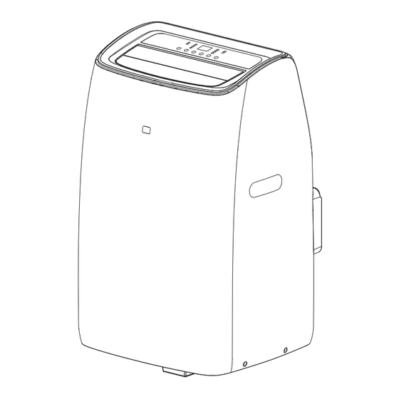
Page 15: Unit Diagram
UNIT DIAGRAM 1. Control Panel 6. Air Intake Grille 11. Central Drainage Outlet 7. Air Outlet Grille 12. Condenser Drain Pipe 2. Handles (on both sides) 3. Casters 8. Air Intake Grille 4. Deflector 9. Power Cable 5. Remote Control 10. -
Page 16: Accessories
ACCESSORIES Parts Parts Name Quantity • Hose inlet 1 Set • Exhaust hose • Hose outlet • Hose inlet 1 Set • Exhaust hose • Hose outlet • Window slider kit 1 Set • Remote control 1 Set • Batteries •... -
Page 17: Installation Instructions
INSTALLATION INSTRUCTIONS Exhauting Hot Air To ensure proper functioning in cool mode, it is crucial that the hot air from the condenser is fully exhausted outside the room. 1. Place the unit on a level floor, ensuring at least 18 inches (45 cm) of clear space around it. - Page 18 The window slider kit is engineered to accommodate most standard vertical and horizontal window configurations. However, adjustments to the installation process may be required for specific window types. This kit can be securely fastened using screws. Important Note If your window opening is smaller than the minimum length of the window slider kit, trim the end without the hole to ensure it fits within the window opening.
- Page 19 Window Slider Kit Installation Components • A) Panel • B) Panel with Hole • C) Screw/Pin Assembly Steps 1. Align Panel B (with hole) into Panel A. Adjust to fit the width of your window. Note that window sizes can vary.
- Page 20 Double-Hung/Sliding Sash Window Installation...
-
Page 21: Display Screen And Control Panel
DISPLAY SCREEN AND CONTROL PANEL 3 4 5 1. Timer Button 2. Fan Speed Button A. Mode Symbol* 3. Decrease Button B. Fan Speed Symbol 4. Display Screen C. Sleep Symbol 5. Increase Button D. Timer Symbol 6. Mode Button E. - Page 22 • Optimal summer room temperature: 24°C to 27°C (75°F to 81°F). • Heat Mode Note: Exclusive to the heat pump model. To activate: • Press Mode button until Heat symbol appears. • Set temperature between 13°C-27°C (55°F-81°F) using Increase or Decrease buttons.
- Page 23 Smart Mode Automatically selects Cool, Fan, or Heat mode based on model. To activate: • Press Mode button until the display changes accordingly. • Choose fan speed (High/Med/Low/Auto). • Operation varies based on room temperature and appliance model. Setting the Timer Use to delay start-up or shutdown.
-
Page 24: Remote Control Usage And Battery Replacement
"FULL TANK": Empty the internal safety tank as instructed in the "End of Season Operations" section. For other codes, contact the service center. REMOTE CONTROL USAGE AND BATTERY REPLACEMENT Display Area Icon Cooling Mode Fan Speed Dry Mode Auto Speed Fan Mode Child Lock Heating Mode... -
Page 25: Remote Appliance Modes
Operating the Remote Control • Point it towards the receiver on the appliance. • Stay within 7 meters of the appliance without any obstacles between the remote and receiver. • Handle the remote with care. Avoid dropping, exposure to direct sunlight, or heat sources. •... - Page 26 Fan Mode No need for the air hose. To set: Press Mode until the " " symbol appears, then select fan speed. Dry Mode Reduces room humidity, ideal for damp conditions. Set like Cool mode, with exhaust hose attached. Fan speed is auto-selected. To set: Press Mode until "...
-
Page 27: Tips For Correct Use
Temperature Unit Switch Change temperature units while the appliance is running. Unit changes as in Fig1 and Fig2. Fig1 Fig2 Setting the Timer Used for delayed start-up or shutdown. To set: Choose mode and temperature, press Timer twice, and adjust time as in Fig 3 and Fig4. Fig 3 Fig 4 Child Lock Function... -
Page 28: Water Drainage Method
• Close windows and doors in the room being air conditioned (see fig. 21). For semi-permanent installation, leave a door slightly ajar (about 1 cm) for proper ventilation. • Minimize sun exposure by partially closing curtains or blinds, making the appliance •... - Page 29 3. Connect the drain hose (1/2" or 12.7mm, possibly supplied). See diagram. 4. The water can be continuously drained through the hose into a floor drain or bucket. 5. Turn on the unit. NOTE: Please be sure that the height of and section of the drain hose should not be higher than that of the drain outlet, or the water tank may not be drained.
-
Page 30: Cleaning
CLEANING on the control panel or remote control, wait for a few minutes then unplug from the mains socket. CLEANING THE CABINET You should clean the appliance with a slightly damp cloth then dry with a dry cloth, may not used water to wash appliance. •... -
Page 31: Troubleshooting
Strictest operation environment: Cooling Mode: Indoors: 18°C-35°C (64°F-95°F), Outdoors: 10°C-43°C (50°F-109°F) Heating Mode: Indoors: 10°C-25°C (50°F-77°F), Outdoors: 10°C-25°C (50°F-77°F) TROUBLESHOOTING Problem Cause Possible Solution The appliance does not There is no current Wait come on It is not plugged into the Plug into the mains mains Wait 30 minutes, if the problem... - Page 32 The appliance does The internal compressor Wait. This delay is part of normal not operate for about safety device prevents operation the appliance from being restarting it restarted until three minutes have elapsed since it was last The following message The appliance has a self See the SELF-DIAGNOSIS Chapter appears on the display:...
-
Page 33: Customer Support
If you wish to contact us by phone, please be sure to have your model number and serial number ready and call us between 9:00am and 6:00pm ET, at +1 866-954-4440. Keep tabs on Impeccaʼs newest innovations and enter contests via our social network feeds: www.facebook.com/Impecca/... -
Page 34: One-Year Limited Appliance Warranty (Us)
ARE GIVEN. connecting cables, batteries and AC adapters. Impecca™ re- serves the right to repair or replace defective products with IMPECCA™ IS NOT RESPONSIBLE OR LIABLE FOR ANY DAM - the same, equivalent or newer models. AGE, WHETHER SPECIAL, INCIDENTAL, CONSEQUENTIAL,... -
Page 35: Notes
NOTES...
Need help?
Do you have a question about the IPAC10-G1 and is the answer not in the manual?
Questions and answers