Advertisement
Quick Links
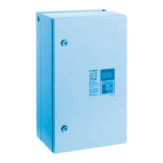
OMRON Varispeed E7 IP54
Frequency Inverter
A l l t r a d e m a r k s , b r a n d n a m e s , a n d b r a n d s a p p e a r i n g h e r e i n a r e t h e p r o p e r t y o f t h e i r r e s p e c t i v e o w n e r s .
• C r i t i c a l a n d e x p e d i t e d s e r v i c e s
• I n s t o c k / R e a d y - t o - s h i p
Artisan Scientific Corporation dba Artisan Technology Group is not an affiliate, representative, or authorized distributor for any manufacturer listed herein.
$
2995
.00
In Stock
Qty Available: 1
New From Surplus Stock
Open Web Page
https://www.artisantg.com/77336-1
• We b u y y o u r e x c e s s , u n d e r u t i l i z e d , a n d i d l e e q u i p me n t
• F u l l - s e r v i c e , i n d e p e n d e n t r e p a i r c e n t e r
Advertisement


Need help?
Do you have a question about the VARISPEED E7 IP54 and is the answer not in the manual?
Questions and answers