Advertisement
Quick Links
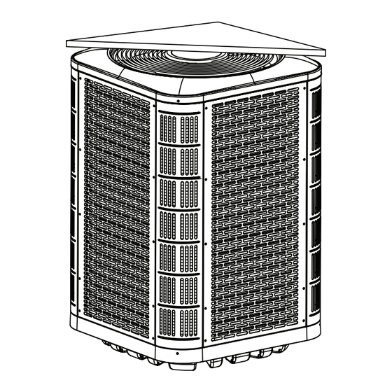
SPLIT SYSTEM HEAT PUMP
INSTALLATION INSTRUCTIONS
*SH3BE4M - 1SP18K, 1SP24K, 1SP30K, 1SP36K, 1SP42K, 1SP48K, & 2SX60K
(1.5, 2, 2.5, 3, 3.5, 4, & 5 TON) SERIES, SINGLE PHASE MODELS WITH MICROCHANNEL COILS
IMPORTANT
ATTENTION INSTALLERS:
It is your responsibility to know this product better
than your customer. This includes being able to install
the product according to strict safety guidelines and
instructing the customer on how to operate and maintain
the equipment for the life of the product. Safety should
always be the deciding factor when installing this product
and using common sense plays an important role as well.
Pay attention to all safety warnings and any other special
notes highlighted in the manual. Improper installation of
the unit or failure to follow safety warnings could result
in serious injury, death, or property damage.
These instructions are primarily intended to assist
qualified individuals experienced in the proper installation
of this appliance. Some local codes require licensed
installation/service personnel for this type of equipment.
Please read all instructions carefully before starting the
installation. Return these instructions to the customer's
package for future reference.
DO NOT DESTROY. PLEASE READ CAREFULLY &
KEEP IN A SAFE PLACE FOR FUTURE REFERENCE.
IMPORTANT SAFETY INFORMATION .......................... 2
HEAT PUMP INSTALLATION ........................................ 3
General Information .................................................................. 3
Before You Install the Heat Pump ............................................ 3
Packaging Removal .................................................................. 3
Locating the Heat Pump ........................................................... 3
Ground Installations.................................................................. 3
Roof Installation ........................................................................ 3
Accessory Mounting Kits .......................................................... 3
Installation/Verification of the System's Expansion Device ...... 4
Connecting Refrigerant Tubing Between the Indoor &
Outdoor Unit ............................................................................. 4
Outdoor Orifice Removal & Installation .................................... 4
ELECTRICAL WIRING ................................................... 5
Pre-Electrical Checklist ............................................................ 5
Line Voltage .............................................................................. 5
Grounding ................................................................................. 6
Thermostat / Low Voltage Connections ................................... 6
START UP & ADJUSTMENTS ....................................... 6
Pre-Start Check List ................................................................. 6
Start-Up Procedures ................................................................ 7
Operating Temperatures........................................................... 7
Air Circulation - Indoor Blower ................................................. 7
Short Cycle Protection ............................................................. 7
System Cooling ........................................................................ 7
System Heating ........................................................................ 7
Defrost Control Board Test Pins............................................... 7
HEAT PUMP MAINTENANCE ........................................ 8
Panel Removal .......................................................................... 8
Panel Installation ...................................................................... 8
REFRIGERANT CHARGING .......................................... 9
Charging the Unit in AC mode .................................................. 9
If the outdoor temperature is 65 degrees F or higher: ........... 10
If the outdoor temperature is between 35 degrees F an
65 degrees F: ......................................................................... 10
If the outdoor temperature is below 35 degrees F: ............... 10
WIRING DIAGRAMS ....................................................... 11
Figure 8. Wiring Diagram for *SH3BE4M1SP (1.5 Ton) ......... 11
Figure 9. Wiring Diagram for *SH3BE4M1SP
(2 Ton - 4 Ton) ........................................................ 12
Figure 10. Wiring Diagram for *SH3BE4M2XP60K
(5 Ton) ................................................................... 13
INSTALLATION CHECKLIST ......................................... 16
REPLACEMENT PARTS ................................................ 16
14.3 SEER2
Advertisement

Related Manuals for Nortek SH3BE4M Series


Summary of Contents for Nortek SH3BE4M Series
- Page 1 SPLIT SYSTEM HEAT PUMP 14.3 SEER2 INSTALLATION INSTRUCTIONS *SH3BE4M - 1SP18K, 1SP24K, 1SP30K, 1SP36K, 1SP42K, 1SP48K, & 2SX60K (1.5, 2, 2.5, 3, 3.5, 4, & 5 TON) SERIES, SINGLE PHASE MODELS WITH MICROCHANNEL COILS IMPORTANT IMPORTANT SAFETY INFORMATION ......2 HEAT PUMP INSTALLATION ........
- Page 2 IMPORTANT SAFETY INFORMATION WARNING: INSTALLER: Please read all instructions before servicing this equipment. Pay attention to all safety warnings and Unless noted otherwise in these instructions, any other special notes highlighted in the manual. Safety only factory authorized parts or accessory markings are used frequently throughout this manual to kits may be used with this product.
- Page 3 HEAT PUMP INSTALLATION Ground Installations The unit should be installed on a solid base, that is level and General Information located at least 2 inches above grade*. *SH3BE4M split system heat pumps are designed only for outdoor rooftop or ground level installations. This unit *Note: It is recommended that poured concrete mounting has been tested for capacity and efficiency in accordance bases are not be attached or adjacent to the building...
- Page 4 The correct tubing bender is recommended. Avoid sharp bends and expansion device or kit is available for all approved Nortek contact of the refrigerant lines with metal surfaces. listed applications from the parts department.
- Page 5 CAUTION: CAUTION: To prevent damage to the unit or internal To prevent damage to the unit or internal components, it is recommended that two components, it is recommended that two wrenches be used when loosening or tightening wrenches be used when loosening or tightening nuts.
- Page 6 Grounding (Optional) WARNING: Green The unit cabinet must have an uninterrupted or unbroken electrical ground to minimize personal injury if an electrical fault should occur. Do not White use gas piping as an electrical ground! Black This unit must be electrically grounded in accordance with local codes or, in the absence of local codes, with the National Electrical Code (ANSI/NFPA 70) or the CSA C22.1 Electrical Outdoor...
- Page 7 √ Verify that any attached indoor ducting has been properly System Cooling installed and sealed. 1. Set the thermostat’s system mode to COOL and the √ Verify that the indoor condensate drain line and trap are fan mode to AUTO. Gradually lower the thermostat properly installed and functioning.
- Page 8 Panel Removal STATUS STATUS DIAGNOSTIC 1. Remove screws securing the panel. INDICATOR TYPE DESCRIPTION 2. Slide the panel up towards the top pan in order to clear Operating Status Cooling, 1st Stage the bottom flange from the base pan. See Figure Operating Status Cooling, 2nd Stage...
- Page 9 1 degree F Nortek does not recommend the use of this product in of the target listed in the table. unlisted combinations, and the system performance and...
- Page 10 5. With the unit in cooling mode, adjust the charge to match If the outdoor temperature is between 35 degrees F and the superheat (for fixed orifice systems) or subcooling (for 65 degrees F: TXV systems) by using the low ambient charging tables on the inside of the outdoor unit's electrical box cover After completing the refrigerant line connections, leak panel.
- Page 11 WIRING DIAGRAMS RED/RED BLACK YELLOW BLACK Figure 8. Wiring Diagram for *SH3BE4M1SP (1.5 Ton)
- Page 12 YELLOW YELLOW BLACK Figure 9. Wiring Diagram for *SH3BE4M1SP (2 Ton - 4 Ton)
- Page 13 Figure 10. Wiring Diagram for *SH3BE4M2XP60K (5 Ton)
- Page 16 Stage-1 Suction Pressure (Low Side): Fan Motor COMPONENTS: Blower Assembly Fan Grille Cabinet Panels Filter/Driers Expansion Valves Specifications & illustrations subject to change without notice or incurring obligations (08/23). 1040988D O’Fallon, MO, © Nortek Global HVAC LLC 2023. All Rights Reserved. (Replaces 1040988C)
Need help?
Do you have a question about the SH3BE4M Series and is the answer not in the manual?
Questions and answers