Table of Contents
Advertisement
Quick Links
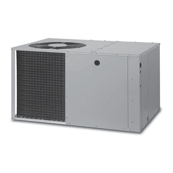
*Q7RF / PPH3RF SERIES
INSTALLATION INSTRUCTIONS
Single Package Heat Pump - Two Stage, R-410A
It is your responsibility to know this product better than your customer. This includes being
able to install the product according to strict safety guidelines and instructing the customer on
how to operate and maintain the equipment for the life of the product. Safety should always be
the deciding factor when installing this product and using common sense plays an important
role as well. Pay attention to all safety warnings and any other special notes highlighted in the
manual. Improper installation of the furnace or failure to follow safety warnings could result in
serious injury, death, or property damage.
These instructions are primarily intended to assist qualified individuals experienced in the
proper installation of this appliance. Some local codes require licensed installation/service
personnel for this type of equipment. Please read all instructions carefully before starting the
installation. Return these instructions to the customer's package for future reference.
DO NOT DESTROY. PLEASE READ CAREFULLY & KEEP IN A SAFE PLACE FOR FUTURE REFERENCE.
IMPORTANT
ATTENTION INSTALLERS:
16 SEER
Advertisement
Table of Contents

Related Manuals for Nortek PPH3RF Series


Summary of Contents for Nortek PPH3RF Series
- Page 1 *Q7RF / PPH3RF SERIES 16 SEER INSTALLATION INSTRUCTIONS Single Package Heat Pump - Two Stage, R-410A IMPORTANT ATTENTION INSTALLERS: It is your responsibility to know this product better than your customer. This includes being able to install the product according to strict safety guidelines and instructing the customer on how to operate and maintain the equipment for the life of the product.
-
Page 2: Table Of Contents
TABLE OF CONTENTS IMPORTANT SAFETY INFORMATION ....3 STARTUP & ADJUSTMENTS ........11 Pre-Start Checklist ..........11 REQUIREMENTS & CODES ........4 Start-Up Procedure ..........11 GENERAL INFORMATION ........4 Air Circulation ............11 Before You Install this Unit ........4 System Heating ...........11 Locating the Heat Pump .........4 System Cooling ...........11 Minimum Clearances ..........4 Short Cycle Protection ........11... -
Page 3: Important Safety Information
IMPORTANT SAFETY INFORMATION WARNING: Please read all instructions before servicing this equipment. Pay attention to all safety warnings and any other special PROPOSITION 65 WARNING: This product notes highlighted in the manual. Safety markings are contains fiberglass wool, a product known to the used frequently throughout this manual to designate a state of California to cause cancer. -
Page 4: Requirements & Codes
REQUIREMENTS & CODES 12" • All electrical wiring must be completed in accordance with local, state & national codes and regulations and with the National Electric Code (ANSI/NFPA 70) or in Canada the Canadian Electric Code Part 1 CSA C.22.1. •... -
Page 5: Air Duct System
Air Duct System HEAT PUMP INSTALLATION Air ducts should be installed in accordance with the Unpacking the Unit standards of the National Fire Protection Association It is recommended that the unit be unpacked at the “Standard for Installation of Air Conditioning and Ventilation installation site to minimize damage due to handling. -
Page 6: Supply Duct
Figure 3. Return & Supply Air Collars Figure 4. Return Air Assembly Supply Duct 1. Assemble the collar by overlapping the two ends. 1. Start the installation from under the home by cutting a NOTE: One end of the collar is slotted and the opposite small hole in the sub-floor. -
Page 7: Condensate Drainage
ELECTRICAL CONNECTIONS WARNING: To avoid electric shock, personal injury, or death, AUTOMATIC DAMPER IS CLOSED WHEN HEAT PUMP IS OFF turn off the electric power at the disconnect or the main service panel before making any electrical connections. • Electrical connections must be in compliance with all applicable local codes and ordinances, and with the current revision of the National Electric Code (ANSI/ NFPA 70). -
Page 8: Overcurrent Protection
protection. Properly sized fuses and breakers also prevent SUPPLY WIRE SUPPLY nuisance trips during unit startup. LENGTH (FEET) CIRCUIT If a fuse blows or a breaker trips, always determine AMPACITY the reason. Do not arbitrarily install a larger fuse or breaker and do not, in any case, exceed the maximum size listed on the data label of the unit. -
Page 9: Thermostat Connections
Thermostat Connections controls high speed cooling and heating operations and the red wire controls the electric heating operation. • The heat-cool thermostat is equipped with a system HEAT-COOL switch, which provides a positive means of preventing simultaneous operation of the heating and CAUTION: cooling units. -
Page 10: 2-Speed Outdoor Fan Motor
2-Speed Outdoor Fan Motor Defrost Control Board Test Pins • Placing a jumper between the test pins for less than 1 (Select Models) second will bypass the Anti-Short Cycle Timer. If the unit utilizes a 2-speed condenser fan motor, this •... -
Page 11: Startup & Adjustments
STARTUP & ADJUSTMENTS Short Cycle Protection The control circuit is equipped with a time-delay feature Pre-Start Checklist for protection against short cycling. With the system The following check list should be observed prior to operating in the cooling mode, gradually raise the starting the unit. -
Page 12: Component Functions
COMPONENT FUNCTIONS CAUTION: Low Pressure Switch (Select Models) - This safety switch is factory installed and located in the suction line The unit should never be operated without a internal to the unit. The switch is designed to protect the filter in the return air system. - Page 13 Q7RF-X24K Charging Chart - Cooling Remove refrigerant when above curve Add refrigerant when below curve Liquid Temperature (Deg. F) Figure 10. Charging Chart for 2 Ton Units Q7RF-X36KA Charging Chart - Cooling Remove refrigerant when above curve Add refrigerant when below curve Liquid Temperature (Deg.
- Page 14 Q7RF-X48K Charging Chart - Cooling Remove refrigerant when above curve Add refrigerant when below curve Liquid Temperature (Deg. F) Figure 12. Charging Chart for 4 Ton Units Q7RF-X60K Charging Chart - Cooling Remove refrigerant when above curve Add refrigerant when below curve Liquid Temperature (Deg.
-
Page 15: Figures & Tables
FIGURES & TABLES Top View 1.75 Ø Electric Heater Power Supply 1.125 Ø Power Supply 0.875 Ø Low Voltage Supply Side View Control Blower Access Panel Access 17.86 Panel 15.36 10.10 1" 3/4" NPT Drain Connection 1.38 18.01 3” 3.2 5.29 12.13 Opening for Opening for... -
Page 16: Wiring Diagrams
Wiring Diagrams Figure 15. W.D. for 2 & 3 Ton Models... - Page 17 Figure 16. W.D. for 4 Ton Models...
- Page 18 Figure 17. W.D. for 5 Ton Models...
-
Page 20: Installation Checklist
Failure to confirm proper charge and airflow may reduce energy efficiency and shorten equipment life. Specifications & illustrations subject to change without notice or incurring obligations (11/17). 10184600 O’Fallon, MO, © Nortek Global HVAC LLC 2017. All Rights Reserved. (Replaces 709584A)
Need help?
Do you have a question about the PPH3RF Series and is the answer not in the manual?
Questions and answers