Advertisement
Quick Links
COSTRUZIONE STRUMENTI OFTALMICI
SLIT LAMP
SERVICE MANUAL
SL9800 / SL9900 / SL9900 ELITE
COSTRUZIONE STRUMENTI OFTALMICI
Via degli Stagnacci 12/E | 50018 Scandicci (FI) | ITALY
Phone: +39 055 722191 | Fax: +39 055 721557
cso@csoitalia.it | www.csoitalia.it
MT805EN_A_01.04 - 04/2023
Color
inside
EN
Advertisement

Related Manuals for CSO SL9800


Summary of Contents for CSO SL9800
- Page 1 COSTRUZIONE STRUMENTI OFTALMICI SLIT LAMP SERVICE MANUAL SL9800 / SL9900 / SL9900 ELITE COSTRUZIONE STRUMENTI OFTALMICI Via degli Stagnacci 12/E | 50018 Scandicci (FI) | ITALY Phone: +39 055 722191 | Fax: +39 055 721557 cso@csoitalia.it | www.csoitalia.it MT805EN_A_01.04 - 04/2023...
- Page 3 ........................10 ISPOSAL AT THE END OF THE USEFUL LIFE DEVICE DESCRIPTION ..........................11 ..............................11 UPPLY DESCRIPTION 3.1.1 SL9800 device ..................................17 3.1.2 SL9900 device ..................................18 3.1.3 Device SL9900 ELITE ................................19 3.1.4 Power supply unit ................................20 3.1.5...
- Page 4 6.5.15 Replacement of the base - [SL9900 and SL9900 ELITE] ....................138 6.5.16 Replacement of the lighting assembly complete with arm - [SL9800] ................143 6.5.17 Replacement of the lighting assembly - [SL9900 and SL9900 ELITE] ................151 ............................159 LECTRICAL SAFETY TEST 6.6.1...
- Page 5 SL9800-SL9900-SL9900 ELITE SERVICE MANUAL MT805EN_A_01.04 - 04/2023 INTRODUCTION The slit lamp is the result of a long research period, carried out by experts in the sector in order to give the product technical innovation, quality and design. This manual is intended for technical personnel only, previously trained and authorized by the Manufacturer to carry out ordinary and corrective maintenance technical interventions.
- Page 6 GENERAL WARNINGS THE INFORMATION GIVEN IN THESE INSTRUCTIONS FOR THE TECHNICAL ASSISTANCE REFER TO THE SLIT LAMPS SL9800, SL9900 AND SL9900 ELITE DEVICES ("DEVICE" FROM NOW ON). Within the instructions for the Technical Assistance, the paragraphs dedicated to one or another device are marked with SL9800, SL9900 or SL9900 ELITE.
- Page 7 - Device serial number - Release of the application software currently in use - Version of the Operating System installed on the PC - LOG file: C:\Program Files\CSO\Phoenix or C:\Program Files (x86)\CSO\Phoenix - LOG file: C:\Program Files\CSO\Phoenix\Live\SLLive.log - C:\Program Files (x86)\CSO\Phoenix\Live\SLLive.log.
- Page 8 SL9800-SL9900-SL9900 ELITE SERVICE MANUAL MT805EN_A_01.04 - 04/2023 SAFETY SAFETY WARNINGS DANGER Danger of electric shock. Do not let water fall on the device. Do not immerse the device in water or other liquids. DANGER Danger of electric shock. Before any maintenance operation, check that the power cables are not damaged.
- Page 9 The digital configuration of the device includes a joystick with button, a digital base with sensor and a beam splitter. SL9800 device, Xx and Xx-D model Fig. 3 - Data plate for the Xx model Fig. 4 - Data plate for the Xx-D model This document is the property of C.S.O.
- Page 10 Fig. 9 - Data plate of the videocamera for the device SL9900 ELITE SL9900 in the model Xx-D in the model Xx-D Fig. 10 - Data plate of the videocamera for the device SL9800 and SL9900 in the model Xx-D 2.2.4 POWER SUPPLY UNIT DATA PLATE Fig.
- Page 11 SL9800-SL9900-SL9900 ELITE SERVICE MANUAL MT805EN_A_01.04 - 04/2023 MEDICAL DEVICE CLASSIFICATION Technical data Value Classification in compliance with annexe VIII of Class I Regulation (EU) 2017/745 ELECTROMEDICAL DEVICE CLASSIFICATION Classification based on the IEC 60601-1:2005 + A1:2012 technical standard Technical data...
- Page 12 SL9800-SL9900-SL9900 ELITE SERVICE MANUAL MT805EN_A_01.04 - 04/2023 DISPOSAL AT THE END OF THE USEFUL LIFE Warnings for the correct disposal of the device in accordance with Directive 2012/19/EU and Directive 2011/65/EU relating to the reduction of the use of hazardous substances in electrical and electronic equipment, as well as waste disposal.
- Page 13 SL9800-SL9900-SL9900 ELITE SERVICE MANUAL MT805EN_A_01.04 - 04/2023 DEVICE DESCRIPTION SUPPLY DESCRIPTION SL9800 device Fig. 12 - Supply description This document is the property of C.S.O. SRL. Any reproduction, even partial, is prohibited. 11/177 11/177...
- Page 14 SL9800-SL9900-SL9900 ELITE SERVICE MANUAL MT805EN_A_01.04 - 04/2023 Name Description Adjustable height. Adjustable distance between Chin rest Optional (*) chin and forehead. Fixation point included. Wheel cover Protection against accidental crushing of fingers. Power supply unit Optional (*) A cable is provided with the power supply unit.
- Page 15 SL9800-SL9900-SL9900 ELITE SERVICE MANUAL MT805EN_A_01.04 - 04/2023 SL9900 device Fig. 13 - Supply description This document is the property of C.S.O. SRL. Any reproduction, even partial, is prohibited. 13/177 13/177...
- Page 16 SL9800-SL9900-SL9900 ELITE SERVICE MANUAL MT805EN_A_01.04 - 04/2023 Name Description Adjustable height. Adjustable distance between Chin rest Optional (*) chin and forehead. Fixation point included. Wheel cover Protection against accidental crushing of fingers. Power supply unit Optional (*) A cable is provided with the power supply unit.
- Page 17 SL9800-SL9900-SL9900 ELITE SERVICE MANUAL MT805EN_A_01.04 - 04/2023 Device SL9900 ELITE Fig. 14 - Supply description This document is the property of C.S.O. SRL. Any reproduction, even partial, is prohibited. 15/177 15/177...
- Page 18 SL9800-SL9900-SL9900 ELITE SERVICE MANUAL MT805EN_A_01.04 - 04/2023 Name Description Adjustable height. Adjustable distance between Chin rest Optional (*) chin and forehead. Fixation point included. Wheel cover Protection against accidental crushing of fingers. Power supply unit Optional (*) A cable is provided with the power supply unit.
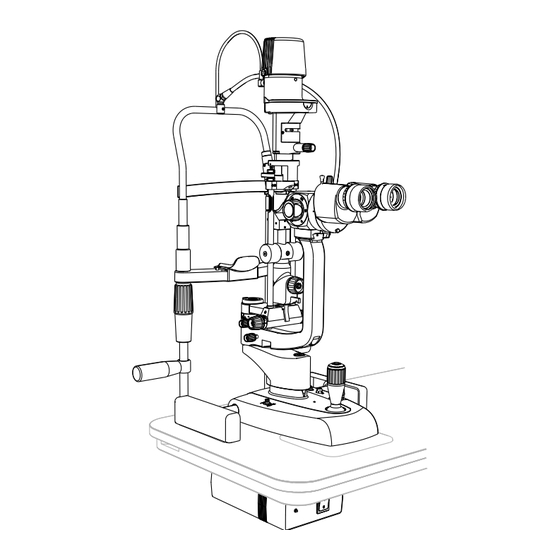
- Page 19 SL9800-SL9900-SL9900 ELITE SERVICE MANUAL MT805EN_A_01.04 - 04/2023 3.1.1 SL9800 DEVICE Fig. 15 - SL9800 device Description Magnification adjuster lens Magnification adjuster Yellow filter Beam splitter (*) Binoculars Eyepieces Eyepiece covers Illuminator (*) Lighting assembly complete with arm Lighting unit Base (*)
- Page 20 SL9800-SL9900-SL9900 ELITE SERVICE MANUAL MT805EN_A_01.04 - 04/2023 3.1.2 SL9900 DEVICE Fig. 16 - SL9900 device Description Lighting unit Light diffusing filter Magnification adjuster lens Yellow filter Eyepiece covers Illuminator (*) Lighting assembly Magnification adjuster Beam splitter (*) Binoculars Eyepieces Base (*)
- Page 21 SL9800-SL9900-SL9900 ELITE SERVICE MANUAL MT805EN_A_01.04 - 04/2023 3.1.3 DEVICE SL9900 ELITE Fig. 17 - SL9900 ELITE device Description Lighting unit Light diffusing filter Magnification adjuster lens Yellow filter Eyepiece covers Illuminator Lighting assembly Magnification adjuster Beam splitter with function keys...
- Page 22 SL9800-SL9900-SL9900 ELITE SERVICE MANUAL MT805EN_A_01.04 - 04/2023 3.1.4 POWER SUPPLY UNIT Fig. 18 - Power supply unit Description Data plate Power supply unit Power indicator light Power switch Power cable connector of the fixation point Connector of the device power supply cable...
- Page 23 SL9800-SL9900-SL9900 ELITE SERVICE MANUAL MT805EN_A_01.04 - 04/2023 3.1.5 CHIN REST Fig. 19 - Chin rest for SL9900 and SL9900 ELITE device (left) and for SL9800 device (right) Description Power cable of the fixation point Chin rest support Chin rest handle...
- Page 24 SL9800-SL9900-SL9900 ELITE SERVICE MANUAL MT805EN_A_01.04 - 04/2023 3.1.6 PERSONAL COMPUTER If the beam splitter is installed on the device, the device shall be used in conjunction with a PC and the Phoenix application software. Read the document "Minimum PC requirements" which can be downloaded from the website www.csoitalia.it...
- Page 25 SL9800-SL9900-SL9900 ELITE SERVICE MANUAL MT805EN_A_01.04 - 04/2023 3.2 TECHNICAL DATA 3.2.1 SL9800 Technical data Value Supply voltage 120-230 V ±10% | 50/60 Hz | 1 A Size (HxWxD) 440 x 313 x 335 mm Device weight 7.4 kg Base movement (x, y, z)
- Page 26 SL9800-SL9900-SL9900 ELITE SERVICE MANUAL MT805EN_A_01.04 - 04/2023 3.2.2 SL9900 AND SL9900 ELITE Technical data Value Supply voltage 120-230 V ±10% | 50/60 Hz | 1 A Size (HxWxD) 675 x 313 x 335 mm Device weight (Xx, Xx-D) 7.8 kg Device weight (ELITE Xx-D) 7.8 kg...
- Page 27 SL9800-SL9900-SL9900 ELITE SERVICE MANUAL MT805EN_A_01.04 - 04/2023 3.2.3 MAGNIFICATION ADJUSTER The magnification adjuster features differ by the chosen configuration: 2x, 3x, 5x and zoom. Magnification adjuster 2x Technical data Value Type Convergent - 2 positions Ocular convergence angle 13° Eyepieces Refractive error compensation ±8 D...
- Page 28 SL9800-SL9900-SL9900 ELITE SERVICE MANUAL MT805EN_A_01.04 - 04/2023 Magnification adjuster Zoom Technical data Value Galilean convergent with continuous variable Type magnification adjuster Ocular convergence angle 6° Eyepieces 12,5x Refractive error compensation ±8 D Declared magnifications 7x / 30x Visual field From 30 mm to 7.4 mm...
- Page 29 SL9800-SL9900-SL9900 ELITE SERVICE MANUAL MT805EN_A_01.04 - 04/2023 INSTALLATION ASSEMBLING THE INSTALLATION ACCESSORIES ON THE TABLE TOP Fig. 21 - Installation accessories on the table top Description Front edge of the table top (Patient side) Left guide rail Sticker pad Sliding plate...
- Page 30 SL9800-SL9900-SL9900 ELITE SERVICE MANUAL MT805EN_A_01.04 - 04/2023 Procedure for assembling the installation accessories on the table top: Install the right and left guide rails on the table top. Use self-tapping screws Ø 2.9 x 13. Install the sliding plate on the table top.
- Page 31 SL9800-SL9900-SL9900 ELITE SERVICE MANUAL MT805EN_A_01.04 - 04/2023 INSTALLING THE DEVICE CAUTION Danger of falling device. The device must be installed on a horizontal and stable surface. Install the guides, the sliding plate and the sticker pad as described in paragraph "Assembling the installation accessories on the table top"...
- Page 32 SL9800-SL9900-SL9900 ELITE SERVICE MANUAL MT805EN_A_01.04 - 04/2023 Place the device on the table top and align the cogwheels on the guide rails. Install the two wheel covers on the guides on the table top. Fig. 27 - Place the device Fig.
- Page 33 SL9800-SL9900-SL9900 ELITE SERVICE MANUAL MT805EN_A_01.04 - 04/2023 If the eye level indicator does not reach the required height, adjust the chin rest. Loosen the 4 locking grub screws placed on the chinrest support. Slide the rods of the chin rest until reaching the required height of 380 mm. Tighten the previously loosened locking grub screws.
- Page 34 SERVICE MANUAL MT805EN_A_01.04 - 04/2023 DEVICE CONNECTIONS SL9800 [Standard configuration] Fig. 33 - SL9800 connections [Standard configuration] Name Connection cable between the base and the lighting unit Power cable of the fixation point Power supply cable of the power supply unit...
- Page 35 SL9800-SL9900-SL9900 ELITE SERVICE MANUAL MT805EN_A_01.04 - 04/2023 SL9800 [Digital configuration] Fig. 34 - SL9800 connections [Digital configuration] Name Connection cable between the base and the lighting unit Power cable of the fixation point Power supply cable of the power supply unit...
- Page 36 SL9800-SL9900-SL9900 ELITE SERVICE MANUAL MT805EN_A_01.04 - 04/2023 SL9900 [Standard configuration] Fig. 35 - SL9900 connections [Standard configuration] Name Connection cable between the base and the lighting unit Power cable of the fixation point Power supply cable of the power supply unit...
- Page 37 SL9800-SL9900-SL9900 ELITE SERVICE MANUAL MT805EN_A_01.04 - 04/2023 SL9900 and SL9900 ELITE [Digital configuration] Fig. 36 - SL9900 and SL9900 ELITE connections [Digital configuration] Name Connection cable between the base and the lighting unit Power cable of the fixation point Power supply cable of the power supply unit...
- Page 38 SL9800-SL9900-SL9900 ELITE SERVICE MANUAL MT805EN_A_01.04 - 04/2023 POSITIONING OF ELECTRICAL CABLES CAUTION Danger of falling device. Do not leave loose cables which may represent an obstacle or danger for the patient or operator. CAUTION Danger of stumbling and falling. Do not let the power or connection cables free in a place where people could walk.
- Page 39 SL9800-SL9900-SL9900 ELITE SERVICE MANUAL MT805EN_A_01.04 - 04/2023 PHOENIX APPLICATION SOFTWARE - [DIGITAL CONFIGURATION] 4.5.1 INSTALLING THE PHOENIX APPLICATION SOFTWARE The following procedure refers to installing the Phoenix application software on a Windows 10 operating system. Switch the power switch of the power supply unit to ON.
- Page 40 SL9800-SL9900-SL9900 ELITE SERVICE MANUAL MT805EN_A_01.04 - 04/2023 Select the destination path of the file. If possible, do not change the default displayed path. Fig. 39 - Selecting the installation folder Click on NEXT to start the installation. Fig. 40 - Installation confirmation This document is the property of C.S.O.
- Page 41 The application software needs administrator privileges to run. If this requirement conflicts with the Company's security policy, contact the CSO Technical Assistance to consider possible solutions. This document is the property of C.S.O. SRL. Any reproduction, even partial, is prohibited.
- Page 42 SL9800-SL9900-SL9900 ELITE SERVICE MANUAL MT805EN_A_01.04 - 04/2023 After the registration procedure, connect with the database through the database configuration window. − If the database has been created during the installation, click on OK. If the database already exists, click on BROWSE and select the desired Phoenix.mdb file.
- Page 43 SL9800-SL9900-SL9900 ELITE SERVICE MANUAL MT805EN_A_01.04 - 04/2023 4.5.2 ACTIVATION AND REGISTRATION OF THE PHOENIX APPLICATION SOFTWARE A license module is available. - LITE Verify the device serial number. All the devices released from 2016 contain their own license. Thus, the software is self-activated when the device is connected to the USB port. In the lower part of the screen a popup that shows the license number, the P-number and the serial number found on the device will be visualized.
- Page 44 SL9800-SL9900-SL9900 ELITE SERVICE MANUAL MT805EN_A_01.04 - 04/2023 The web verification wizard will be displayed. If the computer is connected to the internet, enter the eight-digit serial number found on the device data plate. Choose a verification mode by entering one of the two numbers, then click on VERIFY to complete the procedure.
- Page 45 SL9800-SL9900-SL9900 ELITE SERVICE MANUAL MT805EN_A_01.04 - 04/2023 Wait for the activation code to be communicated. Input the activation code in the activation wizard. The activation form appears on the screen every time the software is restarted. The request code will be also displayed (in the lower part on the right) in this wizard, in the event it had not been recorded during the previous stage.
- Page 46 SL9800-SL9900-SL9900 ELITE SERVICE MANUAL MT805EN_A_01.04 - 04/2023 4.5.3 INSTALLING THE REVIEW STATION Connect the device to the PC and start the Phoenix application software. Read the Software SN (P-number) of the device on the lower left side. Fig. 49 - P-number reading Install the software (Review Station) on the client PC and enter the previously read P- number to activate the software.
- Page 47 SL9800-SL9900-SL9900 ELITE SERVICE MANUAL MT805EN_A_01.04 - 04/2023 Click on NEXT. The software will generate a code. Click on COPY or EXPORT. Send such code to support@csoitalia.it in order to receive the activation code. In the subject line of the e-mail, please write: "Review Station activation".
- Page 48 The application software requires administrator privileges to run, only for the first use (activation and calibration). If this requirement conflicts with the Company's security policy, contact the CSO Technical Assistance to consider possible solutions. During the first Phoenix application software installation, when installing the database, select the desired destination folder.
- Page 49 SL9800-SL9900-SL9900 ELITE SERVICE MANUAL MT805EN_A_01.04 - 04/2023 4.5.5 DICOM ACTIVATION PROCEDURE DICOM is a digital medical standard adopted by many health associations and hospitals from all over the world. It is used by healthcare operators to exchange images and other information through IT systems adopting such standard.
- Page 50 SL9800-SL9900-SL9900 ELITE SERVICE MANUAL MT805EN_A_01.04 - 04/2023 - Lossless compression: to select the compression level to be used during transfer, ranging from 5% to 100% in steps of 5%, in .jpeg format. Otherwise, files are sent in their original format (not compressed).
- Page 51 SL9800-SL9900-SL9900 ELITE SERVICE MANUAL MT805EN_A_01.04 - 04/2023 In case of software updates, the installation window may appear. This means the WCF service menu has been used to install the Web service application interface. Fig. 54 - Installation window Before proceeding, make sure to uninstall the service by following the file path below.
- Page 52 SL9800-SL9900-SL9900 ELITE SERVICE MANUAL MT805EN_A_01.04 - 04/2023 4.5.7 IMPORT AND EXPORT OF EXAMINATIONS To export an examination or a patient folder, right-click on the corresponding line of the Patients / Examinations list, then select the Export symbol. After changing the personal data (not mandatory and for privacy reasons) and confirming export, a file with .zcs extension is...
- Page 53 SL9800-SL9900-SL9900 ELITE SERVICE MANUAL MT805EN_A_01.04 - 04/2023 Turn the filter selector (F) to the through-light position (no filter set). Turn the adjustment dial (G) and set the highest value. Fig. 60 - Turn the filter selector Fig. 61 - Turn the adjustment dial Observe the calibration rod through the eyepieces.
- Page 54 SL9800-SL9900-SL9900 ELITE SERVICE MANUAL MT805EN_A_01.04 - 04/2023 DEVICE START UP - [DIGITAL CONFIGURATION] Read the instructions for use before using the Phoenix application software. The instruction manual can be downloaded from the website www.csoitalia.it or you may read the application software guide.
- Page 55 SL9800-SL9900-SL9900 ELITE SERVICE MANUAL MT805EN_A_01.04 - 04/2023 DIGITAL CALIBRATION OF THE MICROSCOPE - [DIGITAL CONFIGURATION] Digital calibration shall be carried out at the first start-up of the device or after the device has been left unused for a long period of time.
- Page 56 SL9800-SL9900-SL9900 ELITE SERVICE MANUAL MT805EN_A_01.04 - 04/2023 Fig. 66 - Device calibration grid Fig. 67 - Device calibration menu FUNCTIONAL TEST OF THE DEVICE - [DIGITAL CONFIGURATION] After installing the application software, carry out a functional test of the device.
- Page 57 SL9800-SL9900-SL9900 ELITE SERVICE MANUAL MT805EN_A_01.04 - 04/2023 ORDINARY MAINTENANCE SAFETY WARNINGS DANGER Danger of electric shock. Unplug the power supply cable from the power socket before disinfecting or cleaning the device and before any maintenance operation. It is forbidden to carry out any maintenance on the device not mentioned in the instructions for the Technical Assistance.
- Page 58 SL9800-SL9900-SL9900 ELITE SERVICE MANUAL MT805EN_A_01.04 - 04/2023 5.2.1 RECOMMENDED PRODUCTS FOR CLEANING AND DISINFECTION CAUTION Danger of material damage. Do not use solvents, acidic or basic solutions (pH <4,5 or >8,0), abrasive or caustic substances, chlorine-based and chlorine-derived products. The Manufacturer is not liable for any damage caused by using disinfectant products not indicated in this manual.
- Page 59 SL9800-SL9900-SL9900 ELITE SERVICE MANUAL MT805EN_A_01.04 - 04/2023 5.2.4 CLEANING THE APPLIED PARTS CAUTION Danger of material damage. Only use detergent and disinfectant products specifically approved for medical devices or medical-surgical devices. Applied parts that come into direct contact with the patient during the examination shall be thoroughly cleaned after each use with a disinfectant approved for the purpose.
- Page 60 It is prohibited to use a powered screwdriver for any components’ fixing or adjusting procedure. FLOW CHARTS - [DIGITAL CONFIGURATION] Should the instructions given in the flow chart fail to solve the issue, please contact the CSO Technical Assistance. Only use original spare parts to replace device components. The code is indicated within the "Spare parts and accessories list"...
- Page 61 Minimum functional requirement: 3.0 USB port with Texas Instruments or Intel chipset, or Firewire port Texas Instruments and HUB with power supply unit. Use only cables and extensions supplied and certified by CSO See paragraph "Device connections" on page 32.
- Page 62 "Phoenix has stopped working" "C:\programdata\isolatedtorage". - Restart the program. Follow the procedure described (Windows 7/10): - Delete the "CSO" folder from the path "Appdata\Local" of the connected user. If the problem persists: - Delete the setting.jsn file from the folder "C:\programdata\isolatedtorage".
- Page 63 The device has been connected to a USB 2.0 port. bandwidth to start live" USB 3.0 cable damaged. The USB 3.0 cable used is not CSO certified. Replace the USB 3.0 cable with a CSO certified one. This document is the property of C.S.O. SRL.
- Page 64 SL9900 ELITE]" on page 122. - Joystick. Follow the procedure described in paragraph "Replacement of the joystick - [Digital configuration - SL9800]" on page 126 or in paragraph "Replacement of the joystick [Digital configuration - SL9900 and SL9900 ELITE]" on page 129.
- Page 65 LED operation indicator On the device base Green light Red light Orange light Fig. 69 - Light projection [SL9800] Fig. 70 - Light projection [SL9900 and SL9900 ELITE] Pos Description Position Colour code On the calibration tool and on the calibration...
- Page 66 SL9800-SL9900-SL9900 ELITE SERVICE MANUAL MT805EN_A_01.04 - 04/2023 Fig. 71 - Light indicator of the lighting assembly Fig. 72 - Light indicator of the lighting assembly [SL9800] [SL9900 and SL9900 ELITE] Description Position Colour code On the circuit board inside the lighting...
- Page 67 SL9800-SL9900-SL9900 ELITE SERVICE MANUAL MT805EN_A_01.04 - 04/2023 POS Status Meaning Solution Three rapid Option 1 flashes (red- Turn off the power supply green-red light) unit. alternating with Wait until the operation steady green indicator on the device base light. turns off.
- Page 68 SL9800-SL9900-SL9900 ELITE SERVICE MANUAL MT805EN_A_01.04 - 04/2023 POS Status Meaning Solution Turn off the power supply Slow flashes (red- unit. green light). Wait until the operation indicator on the device base Flashes with Device power turns off. variable intensity supply voltage...
- Page 69 SL9800-SL9900-SL9900 ELITE SERVICE MANUAL MT805EN_A_01.04 - 04/2023 POS Status Meaning Solution Turn off the power supply Steady red light. No connection to unit. the cathode No light Wait until the operation (ground) of the projection. indicator on the device base lighting unit.
- Page 70 6.5.1 TESTING THE LIGHTING ASSEMBLY CALIBRATION - [SL9800] The test of the lighting assembly calibration (SL9800) must always be carried out before any corrective maintenance activity on the device SL9800. The test of the lighting assembly calibration (SL9800) must also be carried out following a corrective maintenance activity for the Replacement of the lighting assembly complete with arm - [SL9800] or for the Replacement of the magnification adjuster.
- Page 71 SL9800-SL9900-SL9900 ELITE SERVICE MANUAL MT805EN_A_01.04 - 04/2023 Remove the eyepieces as described in the paragraph "Replacement of the eyepieces" on page 78. Install the eyepiece with reference cross on the binoculars. Bring the orthogonal fiducial lines in vertical and horizontal position.
- Page 72 If the slit projection is not centred, carry out the lighting assembly calibration, as described in the paragraph "Lighting assembly calibration - [SL9800]" on page 148. Remove the eyepiece with reference cross and install the eyepieces as described in the paragraph "Replacement of the eyepieces"...
- Page 73 SL9800-SL9900-SL9900 ELITE SERVICE MANUAL MT805EN_A_01.04 - 04/2023 6.5.2 TESTING THE LIGHTING ASSEMBLY CALIBRATION - [SL9900 AND SL9900 ELITE] The test of the lighting assembly calibration (SL9900 and SL9900 ELITE) must always be carried out before any corrective maintenance activity on the device SL9900 or SL9900 ELITE.
- Page 74 SL9800-SL9900-SL9900 ELITE SERVICE MANUAL MT805EN_A_01.04 - 04/2023 Turn the filter selector (D) to the through light position (no filter set). Turn the knob (E) and set the highest value. Fig. 89 - Turn the filter selector Fig. 90 - Turn the knob Turn the lighting head (F) to the 90°...
- Page 75 SL9800-SL9900-SL9900 ELITE SERVICE MANUAL MT805EN_A_01.04 - 04/2023 While swinging the lighting assembly, check that the vertical projection of the slit remains centred in relation to the reference cross of the eyepiece. Observe the calibration rod through the eyepieces and turn the lighting head (F) to the 0°- 180°...
- Page 76 SL9800-SL9900-SL9900 ELITE SERVICE MANUAL MT805EN_A_01.04 - 04/2023 6.5.3 REPLACEMENT OF THE POWER SUPPLY UNIT Material and warnings: Fig. 98 - Power supply unit Description Code Power supply unit 100259900 (PSP1501) CAUTION Take appropriate precautions when handling components sensitive to electrostatic discharges (ESD).
- Page 77 SL9800-SL9900-SL9900 ELITE SERVICE MANUAL MT805EN_A_01.04 - 04/2023 Disassembling procedure for the power supply unit: Turn off the device and the PC. If present, fasten the table wheels. Lower the brake lever. Disconnect the power cables on the power supply unit.
- Page 78 SL9800-SL9900-SL9900 ELITE SERVICE MANUAL MT805EN_A_01.04 - 04/2023 6.5.4 REPLACEMENT OF THE EYEPIECE COVERS Material and warnings: Fig. 103 - Eyepiece covers Description Code Eyepiece covers 100226627 Sealing ring 100226628 Before carrying out the replacement, make sure you have all the tools and materials required for the installation.
- Page 79 SL9800-SL9900-SL9900 ELITE SERVICE MANUAL MT805EN_A_01.04 - 04/2023 Assembling procedure for the eyepiece covers: Install the sealing rings (A). Install the eyepiece covers on the eyepieces. Fig. 106 - Install the sealing rings Fig. 107 - Install the eyepiece covers This document is the property of C.S.O. SRL.
- Page 80 SL9800-SL9900-SL9900 ELITE SERVICE MANUAL MT805EN_A_01.04 - 04/2023 6.5.5 REPLACEMENT OF THE EYEPIECES Material and warnings: Fig. 108 - Eyepieces Description Code Eyepieces 100226619 Before carrying out the replacement, make sure you have all the tools and materials required for the installation.
- Page 81 SL9800-SL9900-SL9900 ELITE SERVICE MANUAL MT805EN_A_01.04 - 04/2023 6.5.6 REPLACEMENT OF THE BINOCULARS Material and warnings: Fig. 111 - Binoculars Description Code Binoculars (22 mm) 100250600 Before carrying out the replacement, make sure you have all the tools and materials required for the installation.
- Page 82 REPLACEMENT OF THE BEAM SPLITTER [DIGITAL CONFIGURATION] Material and warnings: Fig. 116 - Beam splitter Description Code Beam splitter including USB videocamera 100258305 [SL9800 and SL9900] Beam splitter including USB videocamera 100259300 [SL9900 ELITE] Beam splitter including Firewire videocamera 100250305 [SL9800 and SL9900]...
- Page 83 SL9800-SL9900-SL9900 ELITE SERVICE MANUAL MT805EN_A_01.04 - 04/2023 Disassembling procedure for the beam splitter: Remove the binoculars as described in the paragraph "Replacement of the binoculars" on page 79. Disconnect the connection cable (A) between the beam splitter and the PC.
- Page 84 SL9800-SL9900-SL9900 ELITE SERVICE MANUAL MT805EN_A_01.04 - 04/2023 Assembling procedure for the beam splitter: Place the beam splitter (C) onto the magnification adjuster. Tighten the knob (D) to fasten the beam splitter. Connect the connection cable (B) between the beam splitter and the base.
- Page 85 SL9800-SL9900-SL9900 ELITE SERVICE MANUAL MT805EN_A_01.04 - 04/2023 6.5.8 REPLACEMENT OF THE MAGNIFICATION ADJUSTER Material and warnings: Fig. 123 - Magnification adjuster Description Code Magnification adjuster 5x 100239615 (without yellow filter) Magnification adjuster 3x 100270613 (without yellow filter) Magnification adjuster 5x...
- Page 86 SL9800-SL9900-SL9900 ELITE SERVICE MANUAL MT805EN_A_01.04 - 04/2023 Assembling procedure for the magnification adjuster: Install the magnification adjuster on the arm. Push the magnification adjuster until reaching the stop element (B). Fig. 126 - Install the binoculars Fig. 127 - Stop element Tighten the locking/unlocking knob (A).
- Page 87 The manual calibration of the microscope must only be carried out following a corrective maintenance activity for the Replacement of the magnification adjuster. Carry out the manual calibration of the microscope (SL9800) only after Testing the lighting assembly calibration - [SL9800], if the device is not calibrated.
- Page 88 SL9800-SL9900-SL9900 ELITE SERVICE MANUAL MT805EN_A_01.04 - 04/2023 Manual microscope calibration procedure for SL9800 Turn the power switch of the power supply unit to ON. Remove the cap (A). Insert the calibration rod (B) into its seat (C). Fig. 130 - Remove the cap Fig.
- Page 89 SL9800-SL9900-SL9900 ELITE SERVICE MANUAL MT805EN_A_01.04 - 04/2023 Turn the eyepiece with reference cross (F) to position "0". Turn the magnification adjuster selector (G) and set the maximum magnification value. Fig. 134 - Turn the eyepiece with reference cross Fig. 135 - Turn the magnification adjuster selector Remove the magnification adjuster as described in the paragraph "Replacement of the...
- Page 90 SL9800-SL9900-SL9900 ELITE SERVICE MANUAL MT805EN_A_01.04 - 04/2023 Remove the magnification adjuster as described in the paragraph "Replacement of the magnification adjuster" on page 83. Hold the magnification adjuster and tighten the 3 screws (H) on the bottom of the magnification adjuster.
- Page 91 SL9800-SL9900-SL9900 ELITE SERVICE MANUAL MT805EN_A_01.04 - 04/2023 Observe the calibration rod through the eyepieces and move the microscope back or forth to focus the image. Check the image is in focus. Check the image remains in focus for all available magnification values.
- Page 92 SL9800-SL9900-SL9900 ELITE SERVICE MANUAL MT805EN_A_01.04 - 04/2023 6.5.8.2 MANUAL MICROSCOPE CALIBRATION - [SL9900 AND SL9900 ELITE] The manual calibration of the microscope must only be carried out following a corrective maintenance activity for the Replacement of the magnification adjuster. Carry out the manual calibration of the microscope (SL9900 or SL9900 ELITE) only after Testing the lighting assembly calibration - [SL9900 and SL9900 ELITE], if the device is not calibrated.
- Page 93 SL9800-SL9900-SL9900 ELITE SERVICE MANUAL MT805EN_A_01.04 - 04/2023 Manual microscope calibration procedure for SL9900 and SL9900 ELITE Turn the power switch of the power supply unit to ON. Remove the cap (A). Insert the calibration rod (B) into its seat (C).
- Page 94 SL9800-SL9900-SL9900 ELITE SERVICE MANUAL MT805EN_A_01.04 - 04/2023 Turn the eyepiece with reference cross (F) to position "0". Turn the magnification adjuster selector (G) and set the maximum magnification value. Fig. 152 - Turn the eyepiece with reference cross Fig. 153 - Turn the selector Remove the magnification adjuster as described in the paragraph "Replacement of the...
- Page 95 SL9800-SL9900-SL9900 ELITE SERVICE MANUAL MT805EN_A_01.04 - 04/2023 Hold the magnification adjuster and tighten the 3 screws (H) on the bottom of the magnification adjuster. Reinstall the magnification adjuster as described in the paragraph "Replacement of the magnification adjuster" on page 83.
- Page 96 SL9800-SL9900-SL9900 ELITE SERVICE MANUAL MT805EN_A_01.04 - 04/2023 Check for correct focusing. Remove the eyepiece with reference cross and install the eyepieces as described in the paragraph "Replacement of the eyepieces" on page 78. Remove the calibration rod (B) from its seat (C).
- Page 97 SL9800-SL9900-SL9900 ELITE SERVICE MANUAL MT805EN_A_01.04 - 04/2023 6.5.9 REPLACEMENT OF THE MAGNIFICATION ADJUSTER LENS Material and warnings: Fig. 164 - Magnification adjuster lens Description Code Magnification adjuster lens 100250610 Before carrying out the replacement, make sure you have all the tools and materials required for the installation.
- Page 98 SL9800-SL9900-SL9900 ELITE SERVICE MANUAL MT805EN_A_01.04 - 04/2023 6.5.10 REPLACEMENT OF THE YELLOW FILTER The replacement procedure only applies to devices equipped with magnification adjuster that includes the yellow filter. For the full list of magnification adjusters and their features, refer to the "Spare parts and accessories list"...
- Page 99 SL9800-SL9900-SL9900 ELITE SERVICE MANUAL MT805EN_A_01.04 - 04/2023 Assembling procedure for the yellow filter: Place the yellow filter (D) into the magnification adjuster. Screw in the screw (C) to fasten the yellow filter to the yellow filter insertion rod. Place the plate (A) into the magnification adjuster. Check that the holes (E) on the plate are in the correct position.
- Page 100 SL9800-SL9900-SL9900 ELITE SERVICE MANUAL MT805EN_A_01.04 - 04/2023 6.5.11 REPLACEMENT OF THE PROJECTION MIRROR - [SL9900 AND SL9900 ELITE] Material and warnings: Fig. 173 - Projection mirror Description Code 960206021.O Projection mirror Before carrying out the replacement, make sure you have all the tools and materials required for the installation.
- Page 101 SL9800-SL9900-SL9900 ELITE SERVICE MANUAL MT805EN_A_01.04 - 04/2023 Assembling procedure for the projection mirror: Insert the projection mirror (B) into the seat (C). Turn the lighting assembly (A) to the start position. Fig. 176 - Insert the projection mirror Fig. 177 - Turn the lighting assembly This document is the property of C.S.O.
- Page 102 SL9800-SL9900-SL9900 ELITE SERVICE MANUAL MT805EN_A_01.04 - 04/2023 6.5.12 REPLACEMENT OF THE LIGHTING UNIT - [SL9800] Material and warnings: Fig. 178 - Lighting unit and circuit board Description Code Lighting unit and circuit board 960258527 The code for the lighting unit replacement includes also the circuit board.
- Page 103 SL9800-SL9900-SL9900 ELITE SERVICE MANUAL MT805EN_A_01.04 - 04/2023 Disassembling procedure for the lighting unit: Disconnect the connection cable (A) between the base and the lighting unit from the connector (B). Turn the lighting assembly to access the lighting unit. Fig. 179 - Disconnect the cable Fig.
- Page 104 "Disassembling of the plate - [Standard configuration]" on page 118. In case of digital configuration, follow the procedure described in paragraph "Replacement of the plate - [Digital configuration - SL9800]" on page 120. Access the underside of the base. Unscrew the screws (I).
- Page 105 "Disassembling of the plate - [Standard configuration]" on page 118. In case of digital configuration, follow the procedure described in the paragraph "Replacement of the plate - [Digital configuration - SL9800]" on page 120. This document is the property of C.S.O. SRL.
- Page 106 SL9800-SL9900-SL9900 ELITE SERVICE MANUAL MT805EN_A_01.04 - 04/2023 Place the lighting unit into its seat. Screw in the screws (H) to fasten the lighting unit. Fig. 193 - Place the lighting unit Fig. 194 - Screw in the screws Connect the connection cable (A) between the base and the lighting unit to the connector (E).
- Page 107 SL9800-SL9900-SL9900 ELITE SERVICE MANUAL MT805EN_A_01.04 - 04/2023 6.5.13 REPLACEMENT OF THE LIGHTING UNIT - [SL9900 AND SL9900 ELITE] Material and warnings: Fig. 199 - Lighting unit and circuit board Description Code Lighting unit and circuit board 960259509 The code for the lighting unit replacement includes also the circuit board.
- Page 108 SL9800-SL9900-SL9900 ELITE SERVICE MANUAL MT805EN_A_01.04 - 04/2023 Disassembling procedure for the lighting unit: Unscrew the screws (A). Remove the lighting unit cover. Fig. 200 - Unscrew the screws Fig. 201 - Remove the cover Unscrew the screw (B) of the cable clamp.
- Page 109 SL9800-SL9900-SL9900 ELITE SERVICE MANUAL MT805EN_A_01.04 - 04/2023 Remove the plate. In case of standard configuration, follow the procedure described in the paragraph "Disassembling of the plate - [Standard configuration]" on page 118. In case of digital configuration, follow the procedure described in the paragraph "Replacement of the plate - [Digital configuration - SL9900 and SL9900 ELITE]"...
- Page 110 SL9800-SL9900-SL9900 ELITE SERVICE MANUAL MT805EN_A_01.04 - 04/2023 Assembling procedure for the lighting unit: Place the circuit board. Screw in the screws (P). Fig. 210 – Place the circuit board Fig. 211 - Screw in the screws Connect the connection cable (N) between the base and the circuit board to the connectors J3 and J4 (O).
- Page 111 SL9800-SL9900-SL9900 ELITE SERVICE MANUAL MT805EN_A_01.04 - 04/2023 Install the plate. In case of standard configuration, follow the procedure described in the paragraph "Disassembling of the plate - [Standard configuration]" on page 118. In case of digital configuration, follow the procedure described in the paragraph "Replacement of the plate - [Digital configuration - SL9900 and SL9900 ELITE]"...
- Page 112 Fig. 219 - Screw in the screws When the operation is complete, carry out the electrical safety test as described in the paragraph "Electrical safety test" on page 159. 6.5.14 REPLACEMENT OF THE ILLUMINATOR - [SL9800] Material and warnings: Fig. 220 - Illuminator...
- Page 113 SL9800-SL9900-SL9900 ELITE SERVICE MANUAL MT805EN_A_01.04 - 04/2023 Disassembling procedure for the illuminator: Disconnect the connection cable (A) between the base and the lighting unit from the connector (B). Turn the lighting assembly to access the lighting unit. Fig. 221 - Disconnect the cable Fig.
- Page 114 SL9800-SL9900-SL9900 ELITE SERVICE MANUAL MT805EN_A_01.04 - 04/2023 Assembling procedure for the illuminator: Place the illuminator. Screw in the screw (G) to fasten the illuminator. Fig. 227 - Place the illuminator Fig. 228 - Screw in the screw Connect the connection cable (E) between the lighting unit and the illuminator to the connector (F).
- Page 115 SL9800-SL9900-SL9900 ELITE SERVICE MANUAL MT805EN_A_01.04 - 04/2023 6.5.15 REPLACEMENT OF THE ILLUMINATOR - [SL9900 AND SL9900 ELITE] Material and warnings: Fig. 233 - Illuminator Description Code Illuminator 100270210 CAUTION Take appropriate precautions when handling components sensitive to electrostatic discharges (ESD).
- Page 116 SL9800-SL9900-SL9900 ELITE SERVICE MANUAL MT805EN_A_01.04 - 04/2023 Unscrew the screw (B) of the cable clamp. Disconnect the connection cable (C) between the lighting unit and the illuminator from the connector (D). Fig. 236 - Unscrew the screw and disconnect the cable Turn the slit adjustment knob (E) to lower the component (F).
- Page 117 SL9800-SL9900-SL9900 ELITE SERVICE MANUAL MT805EN_A_01.04 - 04/2023 Remove the locking ring (H) from the rod (I). Remove the round ring (J) from the rod (I). Remove the illuminator (K) from the rod (I). Remove the flat ring (L) from the rod (I).
- Page 118 SL9800-SL9900-SL9900 ELITE SERVICE MANUAL MT805EN_A_01.04 - 04/2023 Screw in the screw (G) of the locking ring. Manually lower the component (F). Fig. 245 - Screw in the screw Fig. 246 - Manually lower the component Connect the connection cable (C) between the lighting unit and the illuminator to the connector (D).
- Page 119 SL9800-SL9900-SL9900 ELITE SERVICE MANUAL MT805EN_A_01.04 - 04/2023 6.5.16 REPLACEMENT OF THE ADDITIONAL LIGHT DIFFUSING FILTER - [SL9900 AND SL9900 ELITE] Material and warnings: Fig. 250 - Additional light diffusing filter Description Code Additional light diffusing filter 100250250 Before carrying out the replacement, make sure you have all the tools and materials required for the installation.
- Page 120 SL9800-SL9900-SL9900 ELITE SERVICE MANUAL MT805EN_A_01.04 - 04/2023 Assembling procedure for the additional light diffusing filter: Insert the light diffusing filter onto the lighting assembly. Lift the light diffusing filter. Fig. 253 - Insert the light diffusing filter Fig. 254 - Lift the light diffusing filter 6.5.17 DISASSEMBLING OF THE PLATE - [STANDARD CONFIGURATION]...
- Page 121 SL9800-SL9900-SL9900 ELITE SERVICE MANUAL MT805EN_A_01.04 - 04/2023 Disassembling procedure for the plate: Place the device horizontally, so that the eyepieces face upwards. Unscrew the four screws (A) on the plate. Fig. 256 - Place the device Fig. 257 - Unscrew the screws Remove the plate.
- Page 122 SL9800-SL9900-SL9900 ELITE SERVICE MANUAL MT805EN_A_01.04 - 04/2023 6.5.18 REPLACEMENT OF THE PLATE - [DIGITAL CONFIGURATION - SL9800] Material and warnings: Fig. 261 - Plate Description Code Plate 100270420 CAUTION Take appropriate precautions when handling components sensitive to electrostatic discharges (ESD).
- Page 123 SL9800-SL9900-SL9900 ELITE SERVICE MANUAL MT805EN_A_01.04 - 04/2023 Disassembling procedure for the plate: Place the device horizontally, so that the eyepieces face upwards. Unscrew the four screws (A) M3x10 on the plate. Fig. 262 - Place the device Fig. 263 - Unscrew the screws Remove the plate.
- Page 124 SL9800-SL9900-SL9900 ELITE SERVICE MANUAL MT805EN_A_01.04 - 04/2023 6.5.19 REPLACEMENT OF THE PLATE - [DIGITAL CONFIGURATION - SL9900 AND SL9900 ELITE] Material and warnings: Fig. 267 - Plate Description Code Plate 100257420 CAUTION Take appropriate precautions when handling components sensitive to electrostatic discharges (ESD).
- Page 125 SL9800-SL9900-SL9900 ELITE SERVICE MANUAL MT805EN_A_01.04 - 04/2023 Disassembling procedure for the plate: Place the device horizontally, so that the eyepieces face upwards. Unscrew the four screws (A) M3x10 on the plate. Fig. 268 - Place the device Fig. 269 - Unscrew the screws Move the plate slightly and disconnect the connection cable (C) between the joystick and the plate sensor from the connector (B).
- Page 126 SL9800-SL9900-SL9900 ELITE SERVICE MANUAL MT805EN_A_01.04 - 04/2023 Assembling procedure for the plate: Bring the plate closer to the base of the device. Connect the connection cable (C) between the joystick and the plate sensor to the connector (B). Connect the connection cable (D) between the connector on the base and the plate sensor to the connector (E).
- Page 127 SL9800-SL9900-SL9900 ELITE SERVICE MANUAL MT805EN_A_01.04 - 04/2023 6.5.20 REPLACEMENT OF THE JOYSTICK [STANDARD CONFIGURATION] Material and warnings: Fig. 275 - Joystick Description Code Joystick 100270404 [Standard configuration] CAUTION Take appropriate precautions when handling components sensitive to electrostatic discharges (ESD). Before carrying out the replacement, make sure you have all the tools and materials required for the installation.
- Page 128 118. When the operation is complete, carry out the electrical safety test as described in the paragraph "Electrical safety test" on page 159. 6.5.21 REPLACEMENT OF THE JOYSTICK - [DIGITAL CONFIGURATION - SL9800] Material and warnings: Fig. 280 - Joystick...
- Page 129 Remove the plate. Follow the procedure described in paragraph "Replacement of the plate - [Digital configuration - SL9800]" on page 120. Unplug the connection cable (A) between the joystick and the sensor from the connector (B). Unscrew the screws (C).
- Page 130 Install the plate. Follow the procedure described in paragraph "Replacement of the plate - [Digital configuration - SL9800]" on page 120. When the operation is complete, carry out the electrical safety test as described in the paragraph "Electrical safety test" on page 159.
- Page 131 SL9800-SL9900-SL9900 ELITE SERVICE MANUAL MT805EN_A_01.04 - 04/2023 6.5.22 REPLACEMENT OF THE JOYSTICK [DIGITAL CONFIGURATION - SL9900 AND SL9900 ELITE] Material and warnings: Fig. 287 - Joystick Description Code Joystick 100270403 [Digital configuration] CAUTION Take appropriate precautions when handling components sensitive to electrostatic discharges (ESD).
- Page 132 SL9800-SL9900-SL9900 ELITE SERVICE MANUAL MT805EN_A_01.04 - 04/2023 Disassembling procedure for the joystick: Remove the plate. Follow the procedure described in paragraph "Replacement of the plate - [Digital configuration - SL9900 and SL9900 ELITE]" on page 122. Unscrew the screws (A) on the joystick.
- Page 133 SL9800-SL9900-SL9900 ELITE SERVICE MANUAL MT805EN_A_01.04 - 04/2023 Assembling procedure for the joystick: Place the bearing (D) on the lower part of the joystick. Place the gasket (C) into its seat inside the disc (B). Place the disc (B) on the lower part of the joystick.
- Page 134 SL9800-SL9900-SL9900 ELITE SERVICE MANUAL MT805EN_A_01.04 - 04/2023 6.5.23 REPLACEMENT OF THE JOYSTICK BUTTON - [DIGITAL CONFIGURATION] Material and warnings: Fig. 294 - Joystick button Description Code Joystick button 100258402 CAUTION Take appropriate precautions when handling components sensitive to electrostatic discharges (ESD).
- Page 135 SL9800-SL9900-SL9900 ELITE SERVICE MANUAL MT805EN_A_01.04 - 04/2023 Assembling procedure for the joystick button: Connect connection cable (A) to the joystick button (B). Insert the joystick button in its seat. Fig. 297 - Connect the cable Fig. 298 - Insert the joystick button When the operation is complete, carry out the electrical safety test as described in the paragraph "Electrical safety test"...
- Page 136 SL9800-SL9900-SL9900 ELITE SERVICE MANUAL MT805EN_A_01.04 - 04/2023 6.5.24 REPLACEMENT OF THE BASE [SL9800] Material and warnings: Fig. 299 - Base Description Code Base for standard configuration [SL9800] 100272410.R 100258527 Lighting unit Base for digital configuration [SL9800] 100274400.D 100258527 Lighting unit Always replace the lighting unit together with the base.
- Page 137 SL9800-SL9900-SL9900 ELITE SERVICE MANUAL MT805EN_A_01.04 - 04/2023 Base disassembling procedure: Disconnect the connection cable (A) between the base and the lighting unit from the connector (B). Disconnect the power cable (D) of the device from the connector (C). Hold the lighting assembly.
- Page 138 SL9800-SL9900-SL9900 ELITE SERVICE MANUAL MT805EN_A_01.04 - 04/2023 Unscrew the screws (H). Remove the lighting unit from its seat. Fig. 306 - Unscrew the screws Fig. 307 - Remove the lighting unit Assembling procedure for the base: Place the lighting unit into its seat.
- Page 139 SL9800-SL9900-SL9900 ELITE SERVICE MANUAL MT805EN_A_01.04 - 04/2023 Turn the lighting assembly until reaching the start position. Insert the structure assembly complete with lighting assembly onto the base. Align the hole on the lighting assembly arm with the track on the base.
- Page 140 SL9800-SL9900-SL9900 ELITE SERVICE MANUAL MT805EN_A_01.04 - 04/2023 6.5.25 REPLACEMENT OF THE BASE - [SL9900 AND SL9900 ELITE] Material and warnings: Fig. 316 - Base Description Code Base for standard configuration [SL9900] 100270410.R 100259509 Lighting unit Base for digital configuration [SL9900] 100270410.D...
- Page 141 SL9800-SL9900-SL9900 ELITE SERVICE MANUAL MT805EN_A_01.04 - 04/2023 Base disassembling procedure: Disconnect the connection cable (A) between the base and the lighting unit from the connector (B). Disconnect the power cable (D) of the device from the connector (C). Hold the lighting assembly.
- Page 142 SL9800-SL9900-SL9900 ELITE SERVICE MANUAL MT805EN_A_01.04 - 04/2023 Unscrew the screw (G) of the cable clamp. If the device is equipped with illuminator, disconnect the connection cable (H) between the lighting unit and the illuminator from the connector (I). Disconnect the connection cable (A) between the base and the lighting unit from the connector (J).
- Page 143 SL9800-SL9900-SL9900 ELITE SERVICE MANUAL MT805EN_A_01.04 - 04/2023 Assembling procedure for the base: Place the lighting unit into its seat. Maintain the connector facing the front part of the device. Screw in the screws (K) to fasten the lighting unit. Fig. 326 - Place the lighting unit Fig.
- Page 144 SL9800-SL9900-SL9900 ELITE SERVICE MANUAL MT805EN_A_01.04 - 04/2023 Insert the structure assembly complete with lighting assembly onto the base. Align the hole on the lighting assembly arm with the track on the base. Screw in the screw (E) to fasten the base to the arm of the magnification adjuster.
- Page 145 SL9800-SL9900-SL9900 ELITE SERVICE MANUAL MT805EN_A_01.04 - 04/2023 6.5.26 REPLACEMENT OF THE LIGHTING ASSEMBLY COMPLETE WITH ARM - [SL9800] Material and warnings: Fig. 335 - Lighting assembly Description Code Lighting assembly complete with arm and circuit 960274500 board The code for the replacement of the lighting assembly complete with arm includes also the circuit board.
- Page 146 "Disassembling of the plate - [Standard configuration]" on page 118. In case of digital configuration, follow the procedure described in the paragraph "Replacement of the plate - [Digital configuration - SL9800]" on page 120. Access the underside of the base.
- Page 147 SL9800-SL9900-SL9900 ELITE SERVICE MANUAL MT805EN_A_01.04 - 04/2023 Unscrew the screws (F). Remove the cogwheel (G). Disconnect the connection cable (H) between the base and the circuit board from the connector J1 (I). Disconnect the connection cable (J) between the base and the circuit board from the connector J2 (K).
- Page 148 "Disassembling of the plate - [Standard configuration]" on page 118. In case of digital configuration, follow the procedure described in the paragraph "Replacement of the plate - [Digital configuration - SL9800]" on page 120. This document is the property of C.S.O. SRL.
- Page 149 When the operation is complete, test the lighting assembly calibration as described in the paragraph "Testing the lighting assembly calibration - [SL9800]" on page 68. When the operation is complete, carry out the electrical safety test as described in the paragraph "Electrical safety test"...
- Page 150 The lighting assembly calibration (SL9800) shall only be carried out following a corrective maintenance activity for the Replacement of the lighting assembly complete with arm - [SL9800]. Carry out the lighting assembly calibration only after Testing the lighting assembly calibration - [SL9800], if the device is not calibrated.
- Page 151 SL9800-SL9900-SL9900 ELITE SERVICE MANUAL MT805EN_A_01.04 - 04/2023 While swinging the lighting assembly, check that the vertical projection of the slit remains centred in relation to the reference cross of the eyepiece. If the slit projection is not centred, slightly loosen one of the two screws (E).
- Page 152 SL9800-SL9900-SL9900 ELITE SERVICE MANUAL MT805EN_A_01.04 - 04/2023 Slightly move the prism-holder head (F) up and down to make the slit projection stable when swinging the lighting assembly. Tighten the screws (E) previously loosened. Fig. 359 - Move the prism-holder head Fig.
- Page 153 SL9800-SL9900-SL9900 ELITE SERVICE MANUAL MT805EN_A_01.04 - 04/2023 6.5.27 REPLACEMENT OF THE LIGHTING ASSEMBLY - [SL9900 AND SL9900 ELITE] Material and warnings: Fig. 361 - Lighting assembly Description Code Lighting assembly [SL9900] 100270511 Lighting assembly [SL9900 ELITE] 100271511 The code for the lighting assembly replacement includes also the circuit board.
- Page 154 SL9800-SL9900-SL9900 ELITE SERVICE MANUAL MT805EN_A_01.04 - 04/2023 Disassembling procedure for the lighting assembly: Disconnect the connection cable (A) between the base and the lighting unit from the connector (B). Remove the cap (C). Fig. 362 - Disconnect the cable Fig. 363 - Remove the cap Remove the Seeger ring (D).
- Page 155 SL9800-SL9900-SL9900 ELITE SERVICE MANUAL MT805EN_A_01.04 - 04/2023 Unscrew the screws (E). Remove the cogwheel (F). Disconnect the connection cable (G) between the base and the circuit board from the connector J1 (H). Disconnect the connection cable (I) between the base and the circuit board from the connector J2 (J).
- Page 156 SL9800-SL9900-SL9900 ELITE SERVICE MANUAL MT805EN_A_01.04 - 04/2023 Assembling procedure for the lighting assembly: Place the circuit board. Screw in the screws (M) to fasten the circuit board. Fig. 370 – Place the circuit board Fig. 371 - Screw in the screws Connect the connection cable (K) between the base and the circuit board to the connectors J3 and J4 (L).
- Page 157 SL9800-SL9900-SL9900 ELITE SERVICE MANUAL MT805EN_A_01.04 - 04/2023 Place the lighting assembly on the structure assembly. Place the Seeger ring (D). Fig. 374 - Place the lighting assembly Fig. 375 - Place the Seeger ring Place the cap (C). Connect the connection cable (A) between the base and the lighting unit to the connector (B).
- Page 158 SL9800-SL9900-SL9900 ELITE SERVICE MANUAL MT805EN_A_01.04 - 04/2023 6.5.27.1 LIGHTING ASSEMBLY CALIBRATION - [SL9900 AND SL9900 ELITE] The lighting assembly calibration (SL9900 and SL9900 ELITE) shall only be carried out following a corrective maintenance activity for the Replacement of the lighting assembly - [SL9900 and SL9900 ELITE].
- Page 159 SL9800-SL9900-SL9900 ELITE SERVICE MANUAL MT805EN_A_01.04 - 04/2023 Procedure for calibrating the lighting assembly: Turn the knob (A) on the calibration rod to adjust the focal distance (B). While adjusting, observe the calibration rod through the eyepieces and swing the lighting assembly (C) by +/- 70°.
- Page 160 SL9800-SL9900-SL9900 ELITE SERVICE MANUAL MT805EN_A_01.04 - 04/2023 Turn the lighting head (G) to the 0°-180° position. Observe the calibration rod through the eyepieces and check the horizontal projection of the slit is centred in relation to the reference cross. Fig. 385 - Turn the lighting head Fig.
- Page 161 MT805EN_A_01.04 - 04/2023 ELECTRICAL SAFETY TEST 6.6.1 SL9800 - [STANDARD CONFIGURATION] The electrical safety test shall always be carried out after a technical intervention on the device, in compliance with EN 60601-1 standard. For proper cable connection and test procedure read the instructions for tester use.
- Page 162 SL9800-SL9900-SL9900 ELITE SERVICE MANUAL MT805EN_A_01.04 - 04/2023 Procedure to carry out the electrical safety test: Before carrying out the test, check that all safety devices have been assembled correctly. Connect the tester as shown in the following figure. Fig. 389 - Connect the tester...
- Page 163 SERVICE MANUAL MT805EN_A_01.04 - 04/2023 6.6.2 SL9800 - [DIGITAL CONFIGURATION] The electrical safety test shall always be carried out after a technical intervention on the device, in compliance with EN 60601-1 standard. For proper cable connection and test procedure read the instructions for tester use.
- Page 164 SL9800-SL9900-SL9900 ELITE SERVICE MANUAL MT805EN_A_01.04 - 04/2023 Procedure to carry out the electrical safety test: Before carrying out the test, check that all safety devices have been assembled correctly. To properly connect the tester, check if the PC is placed inside or outside the patient area.
- Page 165 SL9800-SL9900-SL9900 ELITE SERVICE MANUAL MT805EN_A_01.04 - 04/2023 If the PC is placed outside the patient area, connect the tester as indicated in the following figure. Fig. 391 - Connecting the tester outside the patient area Name Connection between beam splitter and PC...
- Page 166 SL9800-SL9900-SL9900 ELITE SERVICE MANUAL MT805EN_A_01.04 - 04/2023 6.6.3 SL9900 - [STANDARD CONFIGURATION] The electrical safety test shall always be carried out after a technical intervention on the device, in compliance with EN 60601-1 standard. For proper cable connection and test procedure read the instructions for tester use.
- Page 167 SL9800-SL9900-SL9900 ELITE SERVICE MANUAL MT805EN_A_01.04 - 04/2023 Procedure to carry out the electrical safety test: Before carrying out the test, check that all safety devices have been assembled correctly. Connect the tester as shown in the following figure. Fig. 392 - Connect the tester...
- Page 168 SL9800-SL9900-SL9900 ELITE SERVICE MANUAL MT805EN_A_01.04 - 04/2023 6.6.4 SL9900 AND SL9900 ELITE - [DIGITAL CONFIGURATION] The electrical safety test shall always be carried out after a technical intervention on the device, in compliance with EN 60601-1 standard. For proper cable connection and test procedure read the instructions for tester use.
- Page 169 SL9800-SL9900-SL9900 ELITE SERVICE MANUAL MT805EN_A_01.04 - 04/2023 Procedure to carry out the electrical safety test: Before carrying out the test, check that all safety devices have been assembled correctly. To properly connect the tester, check if the PC is placed inside or outside the patient area.
- Page 170 SL9800-SL9900-SL9900 ELITE SERVICE MANUAL MT805EN_A_01.04 - 04/2023 If the PC is placed outside the patient area, connect the tester as indicated in the following figure. Fig. 394 - Connect the tester outside the patient area Name Connection between beam splitter and PC...
- Page 171 SL9800-SL9900-SL9900 ELITE SERVICE MANUAL MT805EN_A_01.04 - 04/2023 TESTING DEVICE OPERATION AFTER MAINTENANCE ACTIVITIES After any maintenance activity, always check the device operation following the table below. Test type Procedure Acceptability criteria Check of the proper operation Perform an acquisition by pressing...
- Page 172 SERVICE MANUAL MT805EN_A_01.04 - 04/2023 SPARE PARTS AND ACCESSORIES LIST Code Description 100259900 Power supply unit (PSP1501) Dust cover with CSO logo 960206C00 [SL9900 and SL9900 ELITE] Dust cover with CSO logo 960102-00 [SL9800] 4014010 Chin cup papers (100 pieces)
- Page 173 Forehead rest 100101136 Sticker pad 100210135 Wheel cover (1 piece) 100210415 Guide rail (1 piece) 100210414 Cogwheel (1 piece) 100272410.R Standard base [SL9800] 100258527 Lighting unit 100274400.D Digital base [SL9800] 100258527 Lighting unit 100270410.R Standard base [SL9900] 100259509 Lighting unit 100270410.D...
- Page 174 MT805EN_A_01.04 - 04/2023 Code Description 100258402 Joystick button Joystick 100270404 [Standard configuration] Joystick 100113401 [Digital configuration - SL9800] Joystick 100270403 [Digital configuration - SL9900 and SL9900 ELITE] 100272600 Magnification adjuster 2x Magnification adjuster 3x 100270613 (without yellow filter) Magnification adjuster 3x...
- Page 175 SL9800-SL9900-SL9900 ELITE SERVICE MANUAL MT805EN_A_01.04 - 04/2023 Code Description Magnification adjuster 5x 100239615_f (with yellow filter) 100271601 Magnification adjuster Zoom 100250600 Binoculars (22 mm) 100226619 Eyepiece (12.5x) 100226627 Eyepiece cover 100226628 Sealing ring 100250610 Magnification adjuster lens Lighting unit with circuit board...
- Page 176 SL9800-SL9900-SL9900 ELITE SERVICE MANUAL MT805EN_A_01.04 - 04/2023 Code Description Lighting assembly complete with arm and 960274500 circuit board [SL9800] Lighting assembly with circuit board 100270511 [SL9900] Lighting assembly with circuit board 100271511 [SL9900 ELITE] Illuminator 100272210 [SL9800] Illuminator 100270210 [SL9900 and SL9900 ELITE]...
- Page 177 SL9800-SL9900-SL9900 ELITE SERVICE MANUAL MT805EN_A_01.04 - 04/2023 Code Description Plate 100270420 [Digital configuration - SL9800] 100250711 Fixation point Projection mirror 960206021.O [SL9900 and SL9900 ELITE] 100214602 Locking/unlocking knob of the binoculars Locking/unlocking knob of the 100214601 magnification adjuster 100257046V0 Lighting unit cover (colour V0)
- Page 178 Description 103005110 Eyepiece with reference cross 200200160 Dioptometer Beam splitter including USB 3.0 video 100258305 camera [SL9800 and SL9900] Beam splitter including USB 3.0 video 100259300 camera [SL9900 ELITE] Beam splitter including USB 3.0 100274310 videocamera (*) [SL9800 and SL9900] USB 3.0 cable 2 m length for 5 MP...
- Page 179 SL9800-SL9900-SL9900 ELITE SERVICE MANUAL MT805EN_A_01.04 - 04/2023 Parts marked with (*) require the Phoenix application software to be upgraded to version 4.XX. Before ordering the part, check the compatibility of the software version. For spare parts or accessories not included in the list, ask the Manufacturer or local Dealer.
- Page 184 COSTRUZIONE STRUMENTI OFTALMICI Via degli Stagnacci 12/E | 50018 Scandicci (FI) | ITALY Phone: +39 055 722191 | Fax: +39 055 721557 cso@csoitalia.it | www.csoitalia.it SL9800-SL9900-SL9900 ELITE | MT805EN_A_01.04 - 04/2023...
Need help?
Do you have a question about the SL9800 and is the answer not in the manual?
Questions and answers