Advertisement
Quick Links
CC2430-CC2591EMK Quick Start Guide
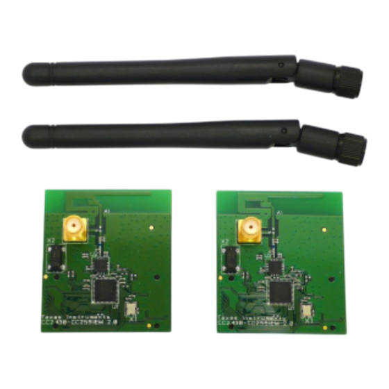
1. Kit Contents
2 x CC2430-CC2591EM
2 x 2.4 GHz antennas
Documentation
4. Set channel
Select a channel between 11 and 26 (2405-
2480 MHz). The channel is selected by
navigating the joystick to the right or left.
Confirm the selection by pressing Button
S1.
7. TX: Select Output Power
On the transmitter node, select the TX
output power (signal strength).Use the
joystick to select between 0 dBm, 13 dBm,
15 dBm, 18 dBm or 19 dBm. Confirm the
selection with Button S1.
10. RX: Observe PER
The PER test receiver will display the PER
value (number of lost and erroneous
packets divided by the total number of
packets sent, displayed as a fraction of
1000). It will also display a moving average
RSSI value (received signal strength). The
test can be reset by pressing Button S1.
2. Plug EM into SmartRF04EB
The CC2430-CC2591EM can be plugged
into the SmartRF04EB. Please refer to the
CC2430DK User Guide for more
information about SmartRF04EB.
5. Select TX or RX
Select receiver on one of the
SmartRF04EB's and transmitter on the
other. Use the joystick to select mode.
Confirm the selection by pressing Button
S1.
8. TX: Select # of Packets
Select burst size (number of packets to
send) by using the joystick, either 1000,
10K, 100K or 1M packets. Confirm the
selection with Button S1.
11. SmartRF Studio
SmartRF® Studio supports the CC2430-
CC2591. When the board is connected to
the SmartRF04EB, it is possible to tick the
CC2591 box in the "Range Extender" pane.
Studio will then make sure that I/O on the
CC2430 is set up for proper control of the
CC2591.
3. Packet Error Rate (PER)
When power is applied to the
SmartRF04EB, the preprogrammed PER
test on the CC2430 will start running. The
LCD will display the screen as shown in the
picture above. The number in the
parentheses is the revision of the CC2430.
Press Button S1 to enter the menu.
6. RX: Select Gain
Select LNA gain on the CC2591 with the
joystick. Either high gain or low gain mode
are possible settings. Normally, high gain
mode should be selected. Confirm the
selection with Button S1. The receiver is
now ready to receive packets.
9. TX: Start PER Test
The transmitter is now configured for the
PER test. The PER test is started by
pushing the joystick (as a button). The
transmitter will display the number of
packets sent during the PER test. The PER
test is stopped by pushing the joystick
again.
12. More Information
For more information about the CC2591,
please visit the product web page on
www.ti.com.
Kit and Software
The source code for the PER tester and
EM reference design can be downloaded
from the CC2430-CC2591EMK web page.
The latest version of SmartRF® Studio can
be downloaded from
www.ti.com/smartrfstudio
We hope you will enjoy working with the
CC2591 and associated LPRF products
from Texas Instruments.
SWRU171A
August 2009
Advertisement

Subscribe to Our Youtube Channel
Related Manuals for Texas Instruments CC2430-CC2591EMK


Summary of Contents for Texas Instruments CC2430-CC2591EMK
- Page 1 Kit and Software The source code for the PER tester and EM reference design can be downloaded from the CC2430-CC2591EMK web page. The PER test receiver will display the PER The latest version of SmartRF® Studio can value (number of lost and erroneous...
- Page 2 IMPORTANT NOTICE Texas Instruments Incorporated and its subsidiaries (TI) reserve the right to make corrections, modifications, enhancements, improvements, and other changes to its products and services at any time and to discontinue any product or service without notice. Customers should obtain the latest relevant information before placing orders and should verify that such information is current and complete.
Need help?
Do you have a question about the CC2430-CC2591EMK and is the answer not in the manual?
Questions and answers