Advertisement
Quick Links
Owner's Manual & Safety Instructions
Save This Manual
operating, inspection, maintenance and cleaning procedures. Write the product's serial number in the
back of the manual (or month and year of purchase if product has no number). Keep this manual and the
receipt in a safe and dry place for future reference.
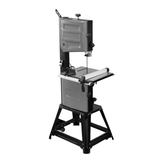
14" STATIONARY WOOD CUTTING
BANDSAW
email our technical support at: productsupport@harborfreight.com
When unpacking, make sure that the product is intact
and undamaged. If any parts are missing or broken,
please call 1-888-866-5797 as soon as possible.
©
Copyright
2024 by Harbor Freight Tools
No portion of this manual or any artwork contained herein may be reproduced in
any shape or form without the express written consent of Harbor Freight Tools.
Diagrams within this manual may not be drawn proportionally. Due to continuing
improvements, actual product may differ slightly from the product described herein.
Tools required for assembly and service may not be included.
Keep this manual for the safety warnings and precautions, assembly,
Visit our website at: http://www.harborfreight.com
Visit our website at: http://www.harborfreight.com
®
. All rights reserved.
24278E-B
read this material before using this product.
Failure to do so can result in serious injury.
SaVe tHiS ManuaL.
24e
70813
70813
Advertisement

Related Manuals for Bauer 24278E-B


Summary of Contents for Bauer 24278E-B
- Page 1 Write the product’s serial number in the back of the manual (or month and year of purchase if product has no number). Keep this manual and the receipt in a safe and dry place for future reference. 24278E-B 14" STATIONARY WOOD CUTTING BANDSAW Visit our website at: http://www.harborfreight.com...
- Page 2 table of contents Safety ..........2 Maintenance ........13 Specifications ........6 Parts List and Diagram ....16 Setup ..........6 Warranty .......... 20 Operation ......... 11 WarninG SyMBOLS anD DeFinitiOnS This is the safety alert symbol. It is used to alert you to potential personal injury hazards. Obey all safety messages that follow this symbol to avoid possible injury or death.
- Page 3 General tool Safety Warnings (cont.) 13. DON’T OVERREACH. Keep proper table a: recOMMenDeD MiniMuM Wire GauGe footing and balance at all times. FOr eXtenSiOn cOrDS (120 VOLt) 14. MAINTAIN TOOLS WITH CARE. Keep eXtenSiOn cOrD tools sharp and clean for best and safest naMepLate performance.
- Page 4 Grounding instructions tO preVent eLectric SHOcK anD DeatH FrOM incOrrect GrOunDinG Wire cOnnectiOn reaD anD FOLLOW tHeSe inStructiOnS: 110-120 Vac Grounded tools: tools with three prong plugs 1. In the event of a malfunction or breakdown, 6. Repair or replace damaged or grounding provides a path of least resistance for worn cord immediately.
- Page 5 Band Saw Safety Warnings (cont.) 13. Only use safety equipment that has been approved 17. Avoid unintentional starting. by an appropriate standards agency. Unapproved Prepare to begin work before turning on the tool. safety equipment may not provide adequate 18. People with pacemakers should consult their protection.
- Page 6 Specifications Electrical Rating 120VAC / 60Hz / 10A Motor No Load Speed 1750 RPM Blade Speed 3600 SFPM (High) 1800 SFPM (Low) Throat Depth 13-3/8″ Cutting Height 8″ Table Pivot (Tilt) Capacity 3° (left) 45° (right) Blade Size 1/8″ to 3/4″ W x 100″ L Dust Port 4″...
- Page 7 Stand assembly note: Stand Legs (178) with rubber foot 3. Attach Short Brace (B) (194) and Roller Wheel located on side of the switch on column. Assembly (187) onto right Stand Legs using Bolts (195), Washers (10), and Nuts (63). note: Stand Legs mount on inside of Saw Base.
- Page 8 5. Attach Foot Pedal Brake Assembly (192) onto Short Brace (A), using Bolts (3), Washers (10) and Nuts (63). 6. Place Band Saw upright. 7. Tighten all Fasteners on Band Saw stand and assembly. 8. Raise Brake Foot Pedal to stabilize the saw nut (63) before proceeding with further assembly.
- Page 9 Squaring Work table to Saw Blade 1. Turn Blade Guide Lock Knob 5. Loosen Work Table Lock Handle and rotate Angle (inner) counterclockwise. Adjustment Handle to align 90° to square. 2. Turn Blade Guide Adjustment Knob 6. Tighten Work Table Lock Handle. (outer) clockwise, while lifting Blade 7.
- Page 10 exhaust port install 1. Connect a dust collection system to Dust Port and secure with hose clamp (not included). Miter Gauge 1. Insert Miter Gauge into desired guide grooves of Work Table. Saw Blade removal 1. Disconnect Band Saw from power source. 2.
- Page 11 Saw Blade tracking and tensioning 1. Disconnect Band Saw from power source. 5. Manually rotate upper Wheel and turn Blade Tracking Adjustment Handle until Blade is 2. Open upper and lower Wheel Cover. centered over upper and lower Wheels. 3. Make sure that Blade Tension Release 6.
- Page 12 Blade Guard 8. Rotate Blade Guard Adjustment Blade Guard Handle to adjust height of blade guide adjustment Lock Handle assembly to 1/8″ from workpiece. Handle 9. Tighten Blade Guard Lock Knob. Lower Blade Guide 1. Loosen two Lock Handles to adjust Guide Bearings. 2.
- Page 13 General Operating instructions tO preVent SeriOuS inJury FrOM entanGLeMent: Keep hands clear of Blade at all times and do not wear gloves when sawing. note: the blade is not tensioned during 2. This Band Saw is designed for cutting hard shipment to prevent damage.
- Page 14 5. Shielded Ball Bearings do not need 8. If storing for a long period, release tension on the lubrication. Small amounts of lightweight Blade using the Blade Tensioning Release Lever. machine oil can be applied to belt tension Refer to, Saw Blade Tracking and Tensioning mechanisms and sliding surfaces.
- Page 15 troubleshooting problem possible causes Likely Solutions Tool will 1. Cord not connected. 1. Check that cord is plugged in. not start. 2. No power at outlet. 2. Check power at outlet. If outlet is unpowered, turn off tool and check circuit breaker. If breaker is tripped, make sure circuit is right capacity for tool and circuit has no other loads.
- Page 16 parts List and Diagram parts List part Description part Description part Description Flat Key (type C) Cylindrical Pin (A) Motor Pulley Fixed Seat (B) Locking Plate Bolt Fixed Seat (A) Spring Plate Motor Components Set Screw 100 Cross Pan Bolt Locking Block Head Screw Dust Outlet...
- Page 17 parts List (continued) part Description part Description part Description 149 Adjusting Screw 173 Door Lock Screw 199 Locking Handle Screw 150 Gear (B) 174 Door Lock Knob 200 Slider (B) 151 Body Assembly 175 Window Bezel 201 Nut 152 Switch Panel 176 Cup Head Square 202 V-Ribbed Belt 153 Switch...
- Page 18 assembly Diagram Page 18 For technical questions, please call 1-888-866-5797. 70813...
- Page 19 assembly Diagram (continued) 70813 For technical questions, please call 1-888-866-5797. Page 19...
- Page 20 Limited 90 Day Warranty Harbor Freight Tools Co. makes every effort to assure that its products meet high quality and durability standards, and warrants to the original purchaser that this product is free from defects in materials and workmanship for the period of 90 days from the date of purchase.
Need help?
Do you have a question about the 24278E-B and is the answer not in the manual?
Questions and answers