Table of Contents
Advertisement
Quick Links
Owner's Manual & Safety Instructions
Save This Manual
operating, inspection, maintenance and cleaning procedures. Write the product's serial number in the
back of the manual near the assembly diagram (or month and year of purchase if product has no number).
Keep this manual and the receipt in a safe and dry place for future reference.
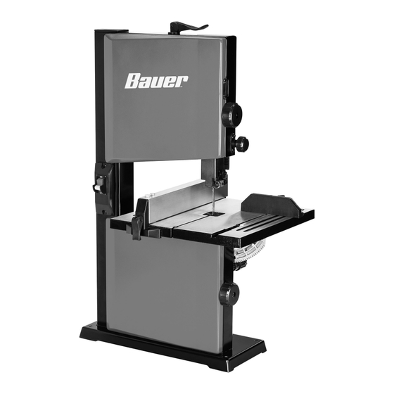
9"
BENCHTOP
BANDSAW
email our technical support at: productsupport@harborfreight.com
When unpacking, make sure that the product is intact
and undamaged. If any parts are missing or broken,
please call 1-888-866-5797 as soon as possible.
©
Copyright
2023 by Harbor Freight Tools
No portion of this manual or any artwork contained herein may be reproduced in
any shape or form without the express written consent of Harbor Freight Tools.
Diagrams within this manual may not be drawn proportionally. Due to continuing
improvements, actual product may differ slightly from the product described herein.
Tools required for assembly and service may not be included.
Keep this manual for the safety warnings and precautions, assembly,
Visit our website at: http://www.harborfreight.com
®
. All rights reserved.
24702E-B
read this material before using this product.
Failure to do so can result in serious injury.
SaVe tHiS ManuaL.
23k
70630
Advertisement
Table of Contents

Subscribe to Our Youtube Channel
Related Manuals for Bauer 24702E-B


Summary of Contents for Bauer 24702E-B
- Page 1 Write the product’s serial number in the back of the manual near the assembly diagram (or month and year of purchase if product has no number). Keep this manual and the receipt in a safe and dry place for future reference. 24702E-B 9" BENCHTOP BANDSAW Visit our website at: http://www.harborfreight.com...
-
Page 2: Important Safety Information
table of contents Safety ............2 Maintenance ..........11 Specifications ..........6 Parts List and Diagram ......14 Setup ............6 Warranty ............ 16 Operation ............ 8 WarninG SyMBOLS anD DeFinitiOnS This is the safety alert symbol. It is used to alert you to potential personal injury hazards. - Page 3 13. DON’T OVERREACH. table a: recOMMenDeD MiniMuM Wire GauGe Keep proper footing and balance at all times. FOr eXtenSiOn cOrDS (120 VOLt) 14. MAINTAIN TOOLS WITH CARE. Keep eXtenSiOn cOrD tools sharp and clean for best and safest naMepLate performance. Follow instructions for LenGtH aMpereS lubricating and changing accessories.
-
Page 4: Grounding Instructions
Grounding instructions tO preVent eLectric SHOcK anD DeatH FrOM incOrrect GrOunDinG Wire cOnnectiOn reaD anD FOLLOW tHeSe inStructiOnS: 110-120 Vac Grounded tools: tools with three prong plugs 1. In the event of a malfunction or breakdown, 6. Repair or replace damaged or grounding provides a path of least resistance for worn cord immediately. -
Page 5: Vibration Safety
11. Stay alert, watch what you are doing and use 14. Avoid unintentional starting. common sense when operating a power tool. Prepare to begin work before turning on the tool. Do not use a power tool while you are tired or 15. -
Page 6: Specifications
Specifications Electrical Rating 120VAC / 60Hz / 2.8A Blade Speed 2500 FPM Throat Depth 9 in. Blade Length 59-1/2 in. Blade Width 1/8 - 3/8" Blade Size (included) 1/4" Setup - Before use: read the entire iMpOrtant SaFety inFOrMatiOn section at the beginning of this manual including all text under subheadings therein before set up or use of this product. - Page 7 Functions Blade tension Lever upper Housing Knob power Switch Guide Height Knob Guide Fence table Blade Blade tracking Knob Blade Guide Base Lock Knob Lower Housing Knob table Lock Knobs tilt Knob Dust port Motor 70630 For technical questions, please call 1-888-866-5797. Page 7...
-
Page 8: Tool Set Up
Operating instructions read the entire iMpOrtant SaFety inFOrMatiOn section at the beginning of this manual including all text under subheadings therein before set up or use of this product. tool Set up tO preVent SeriOuS inJury FrOM acciDentaL OperatiOn: turn the power Switch of the tool off and unplug the tool from its electrical outlet before performing any procedure in this section. -
Page 9: Workpiece And Work Area Set Up
Blade Guide alignment 3. Adjust the Upper Blade Guides (110) by loosening the lower Socket Head Screw (41) and sliding 1. The Blade Guide Assemblies support the Blade at the entire guide bracket until front of bearings the rear and sides. They feature Guide Bearings, are positioned just behind the blade gullets. - Page 10 General Operating instructions tO preVent SeriOuS inJury FrOM entanGLeMent: Keep hands clear of Blade at all times and do not wear gloves when sawing. note: the blade is not tensioned during 4. The Miter Gauge (74) is used to secure the shipment to prevent damage.
-
Page 11: Maintenance And Servicing
Maintenance and Servicing procedures not specifically explained in this manual must be performed only by a qualified technician. tO preVent SeriOuS inJury FrOM acciDentaL OperatiOn: turn the power Switch of the tool off and unplug the tool from its electrical outlet before performing any procedure in this section. -
Page 12: Troubleshooting
troubleshooting problem possible causes Likely Solutions Tool will not start. 1. Cord not connected. 1. Check that cord is plugged in. 2. No power at outlet. 2. Check power at outlet. If outlet is unpowered, turn off tool and check circuit breaker. If breaker is tripped, make sure circuit is right capacity for tool and circuit has no other loads. -
Page 13: Please Read The Following Carefully
pLeaSe reaD tHe FOLLOWinG careFuLLy THE MANUFACTURER AND/OR DISTRIBUTOR HAS PROVIDED THE PARTS LIST AND ASSEMBLY DIAGRAM IN THIS MANUAL AS A REFERENCE TOOL ONLY. NEITHER THE MANUFACTURER OR DISTRIBUTOR MAKES ANY REPRESENTATION OR WARRANTY OF ANY KIND TO THE BUYER THAT HE OR SHE IS QUALIFIED TO MAKE ANY REPAIRS TO THE PRODUCT, OR THAT HE OR SHE IS QUALIFIED TO REPLACE ANY PARTS OF THE PRODUCT. -
Page 14: Parts List And Diagram
parts List and Diagram parts List part Description part Description part Description Lower Wheel Cover Phillips Screw Assy Hex Socket Cap Screw Hex Socket Screw End Cap Blade Tracking Knob Spring Washer Flat Washer Tilt Knob Non-Metallic Insert Nut Frame Phillips Screw Assy Phillips Screw Tracking Lock Lever... -
Page 15: Assembly Diagram
assembly Diagram 44 70 12 11 70630 For technical questions, please call 1-888-866-5797. Page 15... -
Page 16: Limited 90-Day Warranty
Limited 90 Day Warranty Harbor Freight Tools Co. makes every effort to assure that its products meet high quality and durability standards, and warrants to the original purchaser that this product is free from defects in materials and workmanship for the period of 90 days from the date of purchase.
Need help?
Do you have a question about the 24702E-B and is the answer not in the manual?
Questions and answers
What is this pin for
The Bauer 24702E-B pin serves as part of the grounding system for the tool. It provides a path of least resistance for electric current to reduce the risk of electric shock.
This answer is automatically generated