Table of Contents
Advertisement
Quick Links
General Safety Information
WARNING
• Obtain and read the service instructions carefully prior to installing the parts. Loose,
worn, or damaged parts may cause injury to the rider.
We strongly recommend only using genuine Shimano replacement parts.
• Read these Technical Service Instructions carefully, and keep them in a safe place for
later reference.
Note
• Operation of the levers related to gear shifting should be made only when the front chain-
wheel is turning.
• For smooth operation, use the specified outer casing and the bottom bracket cable guide.
• Grease the inner cable and the inside of the outer casing before use to ensure that they
slide properly.
• Use a frame with internal cable routing is strongly discouraged as it has tendencies to
impair the SIS shifting function due to its high cable resistance.
• A special grease is used for the gear shifting cable (SIS-SP41). Do not use DURA-ACE
grease or other types of grease, otherwise they may cause deterioration in gear shifting
performance.
• Parts are not guaranteed against natural wear or deterioration resulting from normal use.
• For maximum performance we highly recommend Shimano lubricants and maintenance
products.
• For any questions regarding methods of installation, adjustment, maintenance or opera-
tion, please contact a professional bicycle dealer.
Note when using the reach adjustment block (Pad spacer)
When installing the 8-degree reach adjustment block, use an anatomic-type handlebar.
If a round-type handlebar is used, the cable stroke may become too short and this can
result in insufficient braking force.
Anatomic type
Round type
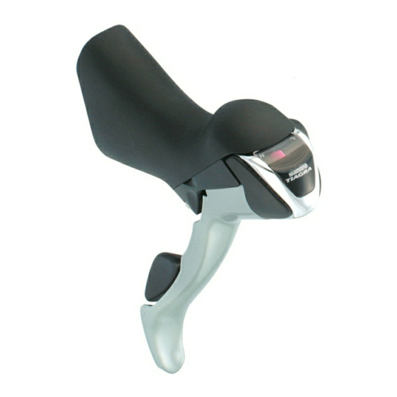
Technical Service Instructions
SI-6LP0A
Shimano Total
ST-4500
Integration
Shimano Total Integration Features
The Shimano Total Integration TIAGRA series features a dual action control lever which
actuates the brakes like a conventional brake lever, and shifts the gears when moved inward
toward the center line of the bicycle. Gear shifting is now possible without ever taking your
hands off the brake hoods or drops.
In order to realize the best performance, we recommend that the following combina-
tion be used.
Series
TIAGRA
Shifting lever
ST-4500
Outer casing
SIS-SP41
Gears
18
27
Front derailleur
FD-4500
FD-4503
Front chainwheel
FC-4500
FC-4503
Bottom bracket
SM-FC4500
Rear derailleur
RD-4500-SS
RD-4500-GS
Freehub
FH-4500
Cassette sprocket
CS-HG50-9
Chain
CN-HG53
Bottom bracket cable guide
SM-SP17
Operation
Rear
Front
Lever
Lever
b
F
B
F
Lever
Lever
a
F
A
F
Lever
F
A
: Shifts from smaller to larger rear sprocket.
Lever
F
B
: Shifts from larger to smaller rear sprocket.
Lever a
: Shifts from smaller to larger chainring.
F
Lever b
: Shifts from larger to smaller chainring.
F
All levers return to the starting position when released.
Operation of rear derailleur lever
• Lever
A
: Shifts from smaller to larger rear sprocket.
• Lever
B
: Shifts from larger to smaller rear sprocket.
F
F
Lever
A
has a click stop at positions ⁄ and ¤.
Press lever
B
once to shift from a larger to one smaller
F
F
sprocket.
Lever
F
B
Lever
F
A
lever
F
A
start position
¤ Click
⁄ Click
E.x. : from 4th to 3rd
⁄ : Shifts one sprocket
4 3
E.x. : from 3rd to 4th
Caution on operation
Lever
F
B
will also move when lever
¤ : Quick-shifts two sprockets
5
3
be careful not to apply pressure to lever
E.x. : from 3rd to 5th
be careful not to press lever
lever
. Gears will not shift when both levers are
F
B
pressed simultaneously.
Be sure to read these service instructions in conjunction with
the service instructions for the RD-4500 before use.
ST-4500 Reach adjustment
If you would like to reduce the reach, remove the bump
rubber and replace it with the accessory pad spacer.
(Two types are available: 4° and 8°.)
Operation of front derailleur levers
(FD-4500 / 4503)
• Lever
F
a
: Shifts from smaller to larger front chainring.
Replacement method
Lever a
F
Lever a
F
1. Remove the bump rubber.
start position
2. Apply a thin layer of grease to the two projections of
the pad spacer.
If operation of lever a does not
3. Press-fit the pad spacer so that the projections go as
complete the chainring shift stroke,
far in as possible.
operate lever a again for the dis-
Bump rubber
tance (X') to complete that part of
the lever stroke (X) which was
short.
Full gear shift stroke
Actual stroke
< FD-4500 >
< FD-4503 >
• Lever
b
: Shifts from larger to smaller front chainring.
• Lever
b
: Shifts from largest chainring to intermediate
F
F
chainring.
Lever b
F
Lever b
Lever b
F
start position
When lever b is operated, there is one click where trim-
ming (the noise prevention mechanism) engages, and a
• Lever
b
: Shifts from intermediate chainring to smallest
F
second stronger click when the
chainring.
gear shift stroke is completed.
After trimming, the next push will
complete the gear shift stroke.
Gear shift
complete stroke
Click
Click
Trim
operation
Trimming (noise prevention operation)
If the chain is on the large or intermediate chainring and
If the front derailleur outer plate and the chain come into
the largest rear sprocket, the chain will rub on the front
contact and generate noise when the chain is on the
derailleur inner plate, producing a characteristic noise.
smallest or intermediate chainring and on one of the
When this happens, press lever b slightly (to the point
smaller sprockets, press lever a slightly to move the front
where it clicks); this causes the front derailleur to move
derailleur slightly toward the largest chainring in order to
slightly toward the smaller chainring, thereby eliminating
eliminate the noise.
the noise.
Caution on operation (FD-4500 / 4503)
Lever
b
will also move when lever a
F
but be careful not to apply pressure to lever
Similarly be careful not to press lever a
Chain position
ating lever
. Gears will not shift when both levers
F
b
are pressed simultaneously.
Movement of the front
Be sure to read these service instructions in conjunction with
derailleur
the service instructions for the FD-4500 / 4503 before use.
Installation
Installation to the handlebar
Secure the assembly with the
installation nut on the outside
of the bracket. Pull the bracket
cover back and use a 5 mm
Allen key to tighten the bolt.
lever
F
B
Installation nut
start position
4
3
Tightening torque:
6 - 8 Nm {50 - 70 in. lbs.}
Installation of the brake cable
Cable used
f
• Inner cable
f
A
is operated, but
F
B
. Similarly
• SLR outer casing
F
A
when operating
F
Be sure to leave some excess cable, even if cutting it to the full length of
the handlebars.
1. Tilt the lever in (as when shifting) to make it easier to pass the
cable through the cable hook.
Note: The front lever cannot be tilted to
the inside until lever
once or twice.
Pad spacer
Pull
Tilt
2. Pass the inner cable through.
Pad spacer
3. Fix the outer guide to the inner cable, and set the angled member
in the bracket.
Note: Do not wipe the grease on the inner cable off.
Also, be careful that the inner cable does not pick
up dust and foreign matter.
Angled member
of outer guide
Bracket
Gear shift
complete stroke
F
Click
Click
4. Set the outer casing on the inner cable, and in the bracket along
the outer guide.
Outer casing
Make sure that the inner
end is firmly seated in the
cable hook.
Gear shift
complete stroke
Cable hook
Click
Click
Inner end
5. Bring the outer casing along the front of the handlebar and cover it
with the outer guide. Now cut the outer guide to the length of the
handlebar, and tape it temporarily in place.
Outer guide
Tape
is operated,
F
b
.
F
when oper-
F
6. Finally, wrap the handlebar with the finish tape.
Installing the shifting cable
Cable used
f
1.2 mm
Bracket cover
• Inner cable (stainless steel)
f
4 mm
• SP41 sealed outer casing (⁄)
5 mm Allen key
f
4 mm
• SP41 outer casing (¤)
¤
⁄
Wire lead
1.6 mm
Cutting the outer casing
5 mm
When cutting the outer casing, cut the opposite end to the end with
the marking. After cutting the outer casing, make the end round so
that the inside of the hole has a
uniform diameter.
Attach the same outer end cap to the cut end of the outer casing.
b
s pushed
F
i
Outer end cap.
• Rear lever
Operate lever
B 8 or more times
F
Lever b
F
to set the lever to the highest posi-
tion, check on the indicator that the
Lever
F
B
highest position is correct, and
Operate at
least 8 times
then install and adjust the inner
cable.
Cable hook
Depress the brake lever, and then
Cable hole
pass the inner cable through the
cable hole.
Inner cable
If the cable hook does not align with the shifting cable hole, press
lever B
F
again until it does, and then install the cable.
Cable hook
Inner cable
Make sure that the inner end is firmly seated in the cable hook.
Outer guide
(Parts sold separately)
Inner end
Cable hook
• Front lever
Operate lever b
F
2 or more times, check
on the indicator that the low position is
correct, and then secure the inner cable.
Operate at least 2 - 3 times
Cable guide
Depress the brake lever, and then
Outer holder
pass the inner cable through the
Cable hole
cable hole.
Outer casing
Inner cable
If the cable hook does not align with the shifting cable hole, press
lever b again until it does, and then install the cable.
Make sure that the inner end is firmly seated in the cable hook.
Cable hook
Outer casing
Inner end
• Outer stopper
1.
Install the outer stopper to the down tube.
Outer stopper
Adjustment bolt
Installation bolt
SP41
SEALED
3mm Allen key
Direct mount seat (M5)
SP41
Tightening torque:
1.5 - 2 Nm {13 - 18 in. lbs.}
Install with the adjustment bolt tightened.
The adjustment range for the adjustment bolt is six full turns.
2.
Pass the inner cable through, and set the outer casing.
Be sure leave some excess in the outer casing, even if cutting it
to the full length of the handlebars.
Outer stopper
Outer casing
Inner cable
Confirm
Make sure the outer casing is
firmly seated in the outer
stopper.
Replacing the bracket cover
The tabs on the bracket cover each fit to a matching slot on the
bracket.
Inner cable
Note the markings:
R : for right
L : for left
Wipe a little rubbing alcohol
inside the bracket cover to
make installation easier.
Lever
b
F
These service instructions are
printed on recycled paper.
One Holland, Irvine, California 92618, U.S.A. Phone: +1-949-951-5003
Industrieweg 24, 8071 CT Nunspeet, The Netherlands Phone: +31-341-272222
3-77 Oimatsu-cho Sakai-ku, Sakai, Osaka 590-8577, Japan
Please note: specifications are subject to change for improvement without notice. (English)
© Mar. 2006 by Shimano Inc. XBC SZK Printed in Japan.
Advertisement
Table of Contents


Need help?
Do you have a question about the TIAGRA ST-4500 - TECHNICAL and is the answer not in the manual?
Questions and answers