Table of Contents
Advertisement
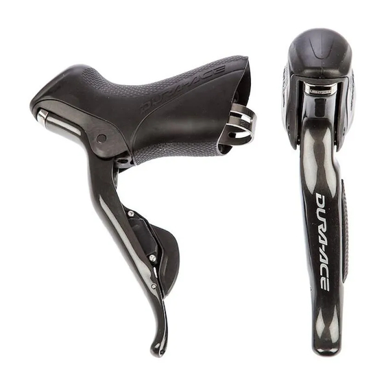
For Right Hand
1
2
8
ITEM
SHIMANO
DESCRIPTION
NO.
CODE NO.
*
Y-6RX
98010
R.H. Main Lever Assembly
1
L.H. Main Lever Assembly
*
Y-6RX
98020
Cable Hook Unit
*
2
Y-6RX
98030
Cable Guide & Fixing Bolt
3
Y-6RX
98040
4
Y-6RX
81000
Return Spring
5
Y-6RX
98050
Lever Axle & Fixing Bolt
6
Y-6RX
98060
Switch Unit Fixing Screw (2 pcs.)
Switch Spring Button (2 pcs.)
7
Y-6RX
98070
Switch Spring (2 pcs.)
8
Y-6RX
98080
Clamp Band Unit ( 23.8 mm Ð 24.2 mm)
9
Y-6RX
98090
10
Y-6RX
78000
Grip Adjusting Screw (M4 x 7.6)
Y-6RX
98100
R.H. Bracket
11
L.H. Bracket
Y-6RX
98110
Dummy Plug ST
12
Y-6RX
32000
Bracket Covers (Pair)
13
Y-6RX
98120
TL-EW01 Plug Tool
14
Y-7CY
02000
DURA-ACE Dual Control Lever
ST-7970
10
11
3
4
7
13
(FLIGHT DECK Compatible)
9
12
5
6
14
For Left Hand
1
2
3
4
8
7
0901-2900
Advertisement
Table of Contents

Subscribe to Our Youtube Channel
Related Manuals for Shimano DURA-ACE ST-7970


Summary of Contents for Shimano DURA-ACE ST-7970
- Page 1 DURA-ACE Dual Control Lever (FLIGHT DECK Compatible) ST-7970 For Right Hand For Left Hand ITEM SHIMANO DESCRIPTION CODE NO. Y-6RX 98010 R.H. Main Lever Assembly L.H. Main Lever Assembly Y-6RX 98020 Cable Hook Unit Y-6RX 98030 Cable Guide & Fixing Bolt...
- Page 2 SI-6RX0A-005-00 SERVICE INSTRUCTIONS INSTRUCTIONS DE MONTAGE INSTRUCCIONES DE SERVICIO 取扱い説明書 ST-7970 DUAL CONTROL LEVER Levier à commande double Palanca de doble control デュアルコントロールレバー...
- Page 3 INDEX English – Gear shifting operation • • • • • • • • • • • • • • • • • • • • Installation • • • • • • • • • • • • • • • • • • • • • • • • • • • • • • Adjustment •...
- Page 4 • Use a soft cloth to clean the carbon fiber and serious injury may occur as a result. We levers, and be sure to moisten the cloth strongly recommend only using genuine Shimano with neutral detergent before using it, replacement parts.
- Page 5 Gear shifting operation Rear shifting switch operation < Shifting switch (X) > < Shifting switch (Y) > The chain moves from a small sprocket to a larger The chain moves from a large sprocket to a smaller sprocket each time the switch is operated. sprocket each time the switch is operated.
- Page 6 Installation Installation to the handlebars Bracket cover Wind the bracket cover from the front, and then use a 5 mm Allen key to tighten the mounting nut in 5 mm Allen key order to secure the bracket cover. When installing the components to carbon frame/handle bar surfaces, verify with the manufacturer of the carbon frame/parts for their recommendation on tightening torque in order to...
- Page 7 Adjustment Adjustment of the rear derailleur (RD-7970) Install the battery. Shift the rear derailleur to the 5th sprocket position. Press the button at the junction (A) of the SM-EW79A until the red LED turns on in order to switch to rear Janction (A) derailleur adjustment mode.
- Page 8 While turning the crank arm, operate shifting switch (X) to move the guide pulley toward the inside until the chain touches the 4th sprocket and makes a slight noise. Next, operate shifting switch (Y) 4 times to move the guide pulley toward the outside by 4 steps to the target position.
- Page 9 Next, carry out the adjustments for the low adjustment bolt and top adjustment bolt. < Low adjustment > Shift the rear derailleur to the largest sprocket, and then tighten the low adjustment bolt until it touches the stopper. 2 mm Allen key Low adjustment bolt <...
- Page 10 Adjustment 6. B-tension adjustment bolt adjustment Largest sprocket Smallest sprocket Set the chain onto the small chainring and the largest sprocket, and then turn the crank arm backward. Turn the B-tension adjustment bolt to adjust so that the guide pulley moves close to the sprocket without obstructing the chain.
- Page 11 Adjustment < Top adjustment > Next, set the chain onto the large chainring and the smallest sprocket. Use a 2 mm Allen key to turn the top adjustment bolt to adjust so that there is a clearance of 0.5 - 1 mm between the chain and the chain guide outer plate.
- Page 12 Maintenance * The illustrations show the right-side lever. Disassembly of the bracket unit and lever unit Use a 2 mm Allen key to remove the lever shaft fixing screw at the bottom of the bracket unit. Lever shaft fixing screw Tap an Allen key or similar tool with a plastic mallet to Lever shaft push out the lever shaft.
- Page 13 Remove the two switch unit fixing screws, and then remove the switches and the switch springs. The bracket unit and the lever unit can then be disassembled. Switch unit fixing screws (#T5 TORX® *) * TORX is a registered trademark of Camcar LLC.
- Page 14 Maintenance Press the switch unit by hand so that the switch springs go into the grooves in the buttons, and then push the shifting switches (X and Y) in as far as they will go. Switch unit Shifting switches (X and Y) Make a gap between the switch unit and the switch unit setting plate and check that the end of the rubber on the switch unit is on the button.
- Page 15 Maintenance Assembly of the bracket unit and lever unit Assemble the bracket unit and the lever unit, attach the return spring, and then press-fit the lever shaft so that it is facing in the correct direction. Then tighten the lever shaft fixing screw to secure the lever shaft.
- Page 16 3-77 Oimatsu-cho, Sakai-ku, Sakai-shi, Osaka 590-8577, Japan * Service Instructions in further languages are available at : http://techdocs.shimano.com Please note: specifications are subject to change for improvement without notice. © Apr. 2010 by Shimano Inc. XBC IZM Printed in Japan...
Need help?
Do you have a question about the DURA-ACE ST-7970 and is the answer not in the manual?
Questions and answers