Advertisement
Advertisement
Table of Contents

Related Manuals for Shimano FlightDeck SC-6500


Summary of Contents for Shimano FlightDeck SC-6500
- Page 2 ® One Holland Irvine CA 92618 U.S.A. Phone 949-951-5003 Industrieweg 24 NL-8071 CT Nunspeet Holland Phone 31-3412-72222 77 Oimatsu-cho 3-cho Sakai Osaka 590-8577 Japan Phone 0722-23-3243...
-
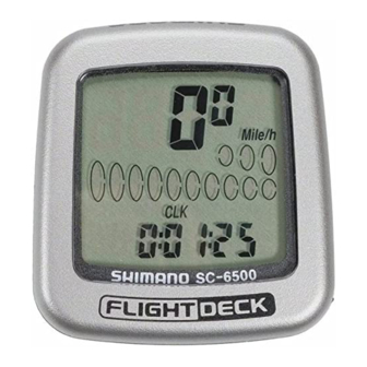
Page 3: Cycle Computer
SI-7AB0D SERVICE INSTRUCTIONS MONTAGE-INSTRUCTIES EINBAUANLEITUNG INSTRUCTIONS DE MONTAGE INSTRUCCIONES DE SERVICIO ISTRUZIONI per l'ASSISTENZA MANUAL DE INSTRUÇÕES Cycle Computer SC-6500/SC-6500-M SC-6500-MX /SC-6500-T ®... - Page 4 English 3 – 24 Dutch 25 – 46 German 47 – 68 French 69 – 90 Spanish 91 – 112 Japanese 113 – 134 Italian 135 – 156 Portuguese 157 – 178...
-
Page 5: Computer From The Bracket Mount
Cycle Computer SC-6500 /SC-6500-M SC-6500-MX /SC-6500-T INDEX 1. External appearance • • • • • • • • • • • 2. Display Contents • • • • • • • • • • • • • • • 3. Display Modes •... - Page 6 Warning Be careful not to pay excessive attention to the computer data while riding, otherwise you might have an accident. Specifications Model No. SC-6500 SC-6500-MX SC-6500-T SC-6500-M ST-M951 ST-M952 SL-M952 ST-6501 ST-T400 STI lever ST-M950 ST-M750 SL-M750 ST-5500-C ST-T300 SL-M951...
-
Page 7: External Appearance
Sub Display (digital) 2 - 14, 16 Rear Switch B Switch A Mode button Battery cap Start stop button AC All clear Switch < SC-6500-M /SC-6500-MX /SC-6500-T > Mode button Start stop button < SC-6500 > Rear STI Brake Bracket... -
Page 8: Display Contents
2. Display Contents mode 1 1. Current speed 2. Clock (VEL) (CLK) 7. Stop watch– trip distance (DST STW) 3. Trip time 6. Stop watch (TIM) 8. Stop watch– average speed 4. Trip distance (AVE STW) (DST) 9. Stop watch– maximum speed 5. - Page 9 mode 2 10. Cadence (rpm) 15. Gear number (digital) 11. Main display 14. Lap counter 16. Gear ratio cadence 17. Gear indicator 12. Maximum (bar) speed 18. Pace Arrow 13. Average speed 19. Low battery display...
-
Page 10: Display Modes
2 Clock Cadence Trip time Main display cadence Trip distance Maximum speed ODO meter Average speed Stop watch Lap counter SC-6500-M SC-6500-MX SC-6500 SC-6500-T Mode Button ST/SP Button Press mode button once Mode Button ST/SP Button Press mode button... - Page 11 ( 1 ) Current speed ( VEL ) km/h, mph 0.0 (2.0) - 130.0km/h 0.0 (1.2) - 80.0mph (Range) When main The current speed will appear at display cadence the top of the main display. appears on top Current speed will appear in the sub - display ( 2 ) Gear indicator ( bar )
- Page 12 ( 4 ) Trip distance group ( TIM, DST, MAX, AVE ) The trip distance group includes trip time (TIM) , trip distance (DST) maximum speed during trip (MAX) average speed during trip (AVE) . To activate the trip distance group, press Mode button to (TIM) and press ST/SP button to activate.
- Page 13 ( 5 ) ODO meter ( ODO ) 0 - 9999.9 km, mile ( 6 ) Stopwatch ( STW ) group This group includes stopwatch trip distance average speed and maximum speed. The stopwatch is activated by pressing ST/SP button. DST, STW While the stopwatch group is operating the stopwatch AVE, STW...
- Page 14 ( 7 ) Cadence ( rpm ) Cadence is calculated from the F - R gear tooth numbers and current speed. Note; Cadence always appears during bicycle movement regardless if the crankarms are rotating. ( 8 ) Main display cadence ( VEL ) Cadence (rpm) can also be shown in main display.
- Page 15 ( 10 ) Digital gear number F - R Gear combinations are displayed when a shift has been made. This will show for approx 4 seconds then original screen will return. The gear combinations are; Gear ratio • Front double •...
- Page 16 ( 14 ) Power saver function When the computer is left without Note; receiving any signal or any button During the stopwatch function the activation the unit will be in a stopwatch will continue to operate “sleep” state and only the clock will even when the power saver appear on the display.
-
Page 17: Setting Tolerances
5. Viewing data after removing the computer from the bracket mount The data can still be viewed even when the computer has been removed from the handlebar bracket. mode1 mode2 DST, STW AVE, STW MAX, STW changes in order when switch B is pressed changes in order when switch A is pressed 6. - Page 18 Install the levers to the handlebars. Then connect and adjust the brake and shifting cables. Refer to the STI Lever Service Instructions for details on these procedures. ( 1 ) Installing the signal cable (SC-6500) Install the signal cable as shown in Figure No1.
-
Page 19: Data Input
Ø 2.1mm or less ( 4 ) Installing the magnet and Fig.4 sensors Use a screwdriver to temporarily secure the magnet to a spoke on the right hand side of the front wheel as shown in fig4. Put a rubber shim between the fork and the sensor as shown in fig5. - Page 20 ( 2 ) Checking the number of chainring and sprocket teeth Check whether the front chainwheel is a double or a triple chainwheel. Example 48x38x28 triple 53x39 Double • • • • • • • • • Check whether the Example cassette has 7,8, or 9 12,13,14,15,16,17,19,21,23...
- Page 21 The value will increase by 5mm each time switch “A” is pressed. The value will change rapidly when switch “A” is pressed continuously. Once the desired value is displayed, press switch “B” for 2 seconds or more to set. In the case of tires which have circumference of less than 2050mm, press switch “A”...
- Page 22 ( 5 ) Entering the number of chainring and sprocket teeth The display will then change to that shown in fig8. Fig.8 Inner Outer chainring chainring Front chainring (3S) Rear sprocket (9S) Low gear Top gear The following tooth numbers are pre - set into the computer No.
- Page 23 Enter the number of teeth for the inner chainring (for double front chainwheel) or the middle chainring (for triple front chainwheel). “38” will flash on the display. This Fig.10 position can be set from 20 - 50 by the same procedure of setting outer chainring.
- Page 24 If the cassette has seven sprockets, press switch “A” once to change the flashing “21” to “- -”, and then press switch B once. This will indicate that there is no 8th sprocket, and the operation for entering the number of sprocket teeth will be complete.
- Page 25 ( 7 ) Setting the time Fig.14 ( 24 hour format ) The display will change to that shown in fig 14. Set the time to one minute later than the current time. Example If the time is 10:46:23 10:47: - - •...
-
Page 26: Troubleshooting
@ @ @ @ @ @ @ @ e ? @ @ @ @ @ @ @ @ e ? @ @ @ @ @ @ @ @ ? e @ @ @ @ @ @ @ @ e ? @ @ @ @ @ @ @ @ ? e @ @ @ @ @ @ @ @ e ? @ @ @ @ @ @ @ @ ? e @ @ @ @ @ @ @ @ e ? @ @ @ @ @ @ @ @ ? e @ @ @ @ @ @ @ @ e ? @ @ @ @ @ @ @ @ ? e @ @ @ @ @ @ @ @ e ? @ @ @ @ @ @ @ @ ? e @ @ @ @ @ @ @ @ e ? @ @ @ @ @ @ @ @ ? e @ @ @ @ @ @ @ @ e ? @ @ @ @ @ @ @ @ ? e @ @ @ @ @ @ @ @ e ? @ @ @ @ @ @ @ @ ? e @ @ @ @ @ @ @ @ e ? @ @ @ @ @ @ @ @ ? e @ @ @ @ @ @ @ @ e ? @ @ @ @ @ @ @ @ ? e @ @ @ @ @ @ @ @ e ? @ @ @ @ @ @ @ @ ? e @ @ @ @ @ @ @ @ e ? @ @ @ @ @ @ @ @ ? e @ @ @ @ @ @ @ @ e ? @ @ @ @ @ @ @ @ ? e @ @ @ @ @ @ @ @ @ @ @ @ @ @ @ @ e ? @ @ @ @ @ @ @ @...
Need help?
Do you have a question about the FlightDeck SC-6500 and is the answer not in the manual?
Questions and answers