Advertisement
Available languages
Available languages
Quick Links
Model # XL-45BR / XL-45BR-EC
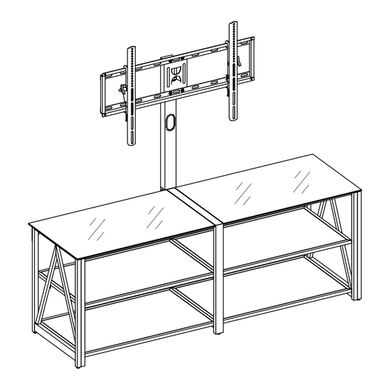
This item is designed to be a 3-in-1 configuration. Please choose the option that best suits your needs. DO NOT
discard any of the hardware or parts that you will not use on your chosen option. This will allow you to use this
TV Console in different configurations at a later date, if desired.
Floating Swivel Mount
If you have any questions regarding assembly or if parts are missing, DO NOT return this item to the store
where it was purchased. Please call our customer service number and have your instructions and parts list
ready to provide the model name, part name or factory number:
Or visit our web site 24 hours a day, 7 days a week for product assistance at
THIS INSTRUCTION BOOKLET CONTAINS IMPORTANT SAFETY INFORMATION.
3-in-1
U.S. Patent 8,561,551
CA Patent 2,811,974
ADULT ASSEMBLY REQUIRED
Pacific Standard Time: 8:30 a.m. - 4:30 p.m., Monday - Friday
www.whalenstyle.com
Or e-mail your request to parts@whalenfurniture.com
PLEASE READ AND KEEP FOR FUTURE REFERENCE.
Date 2023-12-22
TM
TV Stand
TV sold separately
TV
Tilting Wall Mount
1-866-942-5362
Rev. 0001-B
LOT NUMBER:
DATE PURCHASED: / /
TV
Table-top Console
Advertisement

Related Manuals for Whalen Furniture XL-45BR


Summary of Contents for Whalen Furniture XL-45BR
- Page 1 LOT NUMBER: DATE PURCHASED: / / 3-in-1 TV Stand Model # XL-45BR / XL-45BR-EC U.S. Patent 8,561,551 CA Patent 2,811,974 This item is designed to be a 3-in-1 configuration. Please choose the option that best suits your needs. DO NOT discard any of the hardware or parts that you will not use on your chosen option.
- Page 2 G E N E R A L I N F O R M A T I O N , T I P S a n d T R I C K S 1. Please read the Assembly Instructions prior to assembling this product. 2.
- Page 3 Parts and Hardware List Please read completely through the instructions and verify that all listed parts and hardware are present before beginning assembly. A- Top Frame (Qty. 2) B- Middle / Bottom Shelf (Qty. 4) C- Upper Spine (Qty. 1) D- Left Side Frame (Qty.
- Page 4 Parts and Hardware List Please read completely through the instructions and verify that all listed parts and hardware are present before beginning assembly. (5) Lock Washer (6) Flat Washer (7) Concrete Anchor (8) 2-1/2” Lag Bolt (Qty. 46+2 extra) (Qty. 46+2 extra) (Qty.
- Page 5 Assembly Instructions Support surface ④ x 4 The threaded sockets face downward. NOTE: Please do not fully tighten all bolts until you finish assembling all parts. Once assembled, go back and fully tighten all bolts. This will make the assembly easier. 1.
- Page 6 Assembly Instructions ④ x 4 ⑤ x 4 ⑥ x 4 4. Fasten the Middle Shelves (B) to the Middle Frame (E) with four 1” Bolts (4), four Lock Washers (5) and four Flat Washers (6) as shown.
- Page 7 Assembly Instructions ③ x 2 ⑤ x 2 ⑥ x 2 5. Align one U-shaped Bracket (11) to the threaded sockets on both Middle Shelves (B) and fasten it into place with two 5/8” Bolts (3) and two Washers (5 and 6).
- Page 8 Assembly Instructions ④ x 4 ⑤ x 4 ⑥ x 4 6. Fasten the Bottom Shelves (B) to the Middle Frame (E) with four 1” Bolts (4), four Lock Washers (5) and four Flat Washers (6).
- Page 9 Assembly Instructions ③ x 2 ⑤ x 2 ⑥ x 2 7. Align the other U-shaped Bracket (11) to the threaded sockets on both Bottom Shelves (B) and fasten it into place with two 5/8” Bolts (3) and two Washers (5 and 6).
- Page 10 Assembly Instructions ③ x 8 ⑤ x 8 ⑥ x 8 8. Align and attach the Left Side Frame (D) to both Middle and Bottom Shelves (B) with four 5/8” Bolts (3) and four Washers (5 and 6). 9. Repeat the same procedure to attach the Right Side Frame (F) at the opposite end.
- Page 11 Assembly Instructions ④ x 4 10. Fasten the Top Frames (A) to both Side Frames (D and F) with four 1” Bolts (4).
- Page 12 Assembly Instructions ③ x 8 ⑤ x 8 ⑥ x 8 11. Ask for assistance to stand the assembled unit upright and position it near the final location. 12. Align the Side Brackets (J) to the threaded sockets on both Top Frame (A) and Side Frames (D and F) properly.
- Page 13 Assembly Instructions ③ x 6 ⑤ x 6 ⑥ x 6 13. Align the Middle Brackets (K and L) to the threaded sockets on both Top Frames (A) and Middle Frame (E) and fasten the Middle Brackets (K and L) into place with three 5/8” Bolts (3) and three Washers (5 and 6) per bracket.
- Page 14 Assembly Instructions for Table-top Display ⑩ x 1 14. Plug the Spine End Cap (10) all the way onto the top of the Middle Frame (E).
- Page 15 Assembly Instructions for Table-top Display Back view ③ x 4 15. Attach 2 Cable Wheels (N) to the backside of Middle Frame (E) with the 5/8” Bolts (3). Tighten the bolts with the enclosed 4 mm hex wrench. NOTE: You can use the Cable Wheels to help keep your entertainment center’s cables and cords organized.
- Page 16 Assembly Instructions for Table-top Display ① x 12 16. Put the Suction Cups (1) firmly into the holes on the metal tabs on Top Frames (A) as shown. TIP: If a suction cup resists insertion, try pressing down on the middle of the cup with the hex wrench while twisting it clockwise into the hole.
- Page 17 Assembly Instructions for Table-top Display Wooden stud Wall Use existing bolt Nylon strap Wall Long screw Metal bracket Floor leveler Tools required: Hex wrench (provided), Phillips screwdriver, power drill and 1/8” drill bit (not provided). NOTE: When moving the unit, have someone help you grab the metal frames instead of the glasses to prevent the glasses from falling or breaking.
- Page 18 A s s e m b l y I n s t r u c t i o n s f o r F l o a t i n g S w i v e l M o u n t 3 5 6 ③...
- Page 19 Assembly Instructions for Floating Swivel Mount ③ x 4 ⑤ x 4 ⑥ x 4 21. Fasten the Swiveling Bracket (G) to the top of the Upper Spine (C) with four 5/8” Bolts (3) and four Washers (5 and 6). Turn the Swiveling Bracket against the Upper Spine (C) when tightening the bolts with the enclosed 4 mm hex wrench.
- Page 20 Assembly Instructions for Floating Swivel Mount ② x 4 ⑤ x 4 ⑥ x 4 22. Hold and attach the flat side of the Mounting Frame (H) onto the Swiveling Bracket (G) using four 1/2” Bolts (2) and the Washers (5 and 6).
- Page 21 Assembly Instructions for Floating Swivel Mount ③ x 4 23. Attach 2 Cable Wheels (N) to the backside of the Upper Spine (C) and Middle Frame (E) with the 5/8” Bolts (3). Tighten the bolts with the enclosed 4 mm hex wrench. NOTE: You can use the Cable Wheels to help keep your entertainment center’s cables and cords organized.
- Page 22 Assembly Instructions for Floating Swivel Mount ① x 12 24. Put the Suction Cups (1) firmly into the holes on the metal tabs on Top Frames (A) as shown. 25. Place the Top Glasses (M), with the black side of the glass down, onto the Suction Cups (1) on the shelf frames.
- Page 23 Assembly Instructions for Floating Swivel Mount Wooden stud Wall Use existing bolt Nylon strap Wall Metal bracket Long screw Floor leveler Tools required: Hex wrench (provided), Phillips screwdriver, power drill and 1/8” drill bit (not provided). NOTE: When moving the unit, have someone help you grab the metal frames instead of the glasses, from the front of the unit, to prevent the glasses from falling or breaking.
- Page 24 Mounting the Monitor Brackets to a television with a Flat Back AAA / CCC EEE / GGG LLL / MMM NNN / OOO IL / IR LL / LR BBB / DDD FFF / HHH / III / JJJ LLL / MMM LL / LR IL / IR NNN / OOO...
- Page 25 Mounting the Monitor Brackets to a television with a Curved/Recess Back LL / LR IL / IR LL / LR IL / IR / III / LL / LR IL / IR LL / LR IL / IR 30. Determine the correct diameter of the bolt the TV requires by hand threading them into the threaded insert on the back of the TV.
- Page 26 Assembly Instructions for Floating Swivel Mount I L/ I R I L/ I R MAKE SURE ALL BOLTS ARE TIGHT AND THE SPINE IS AT A 90 DEGREE ANGLE AND VERIFY THE MOUNTING FRAME IS LEVEL, USING A QUALITY LEVEL, PRIOR TO INSTALLATION OF TV.
- Page 27 Assembly Instructions for Floating Swivel Mount Turn clockwise to tighten. Turn counter-clockwise to loosen. [If unable to tighten by hand, use 3/16” hex wrench for extra leverage.] 35. The Monitor Brackets (IL / IR) can tilt up to 11˚ downward and 5˚ upward, depending on your optimum viewing position.
- Page 28 The following steps are only for those who wish to mount their TV directly to the wall. If you have already mounted your TV to the Swinging Floater or plan to display your TV on the top surface of the Console, disregard the following steps.
- Page 29 Assembly Instruction for installing the Mounting Frame onto BRICK, SOLID CONCRETE OR CONCRETE BLOCK WALLS 406.4 mm 16 in. / pulg. 166 mm 6.5 in. / pulg. 63.5 mm 2.5 in. / pulg. Maximum weight 135 lb (61.2 kg) Concrete Anchors should only be used for masonry mounting. NEVER use the wall anchors to mount the unit to drywall.
- Page 30 Assembly Instructions 42. Attach the Monitor Brackets (IL / IR) to the back of the television following steps 28 and 29, or 30 and 31, depending on the type of TV that you own. 43. Once the Monitor Brackets (IL / IR) are attached onto the back of the television, ask for assistance to lift the television up to attach the Monitor Brackets onto the Mounting Frame (H).
-
Page 31: Care And Maintenance
Care and Maintenance For everyday cleaning, chrome, brass, aluminum, and painted metal surfaces can be kept looking their best by wiping with a slightly damp, soft cotton cloth, or vacuum cleaner brush. If soiled, wipe with clean sponge or cloth wrung out of water. Wipe dry with cloth or paper towel to avoid water spots. -
Page 32: Quality Guarantee
Should this product be defective in workmanship or materials or fail under normal use, we will repair or replace it for up to one (1) year from date of purchase. Every Whalen Furniture product is designed to meet your highest expectations. - Page 33 NÚMERO de LOTE: FECHA de COMPRA: / / Consola para Televisión 3-en-1 Modelo # XL-45BR / XL-45BR-EC Patente de U.S. 8,561,551 Patente de CA 2,811,974 Esté producto está diseñado para ser una configuración 3-en-1. Por favor escoja la opción que mejor sirva a sus necesidades.
- Page 34 I N F O R M A C I O N G E N E R A L , R E C O M E N D A C I O N E S Y T R U C O S 1.
- Page 35 Lista de partes y material de ferretería Por favor lea completamente las instrucciones y verifique que estén todas las partes y partes de ferretería antes de iniciar el ensamblado. A- Marco superior (Cant. 2) B- Repisa media / inferior (Cant. 4) C- Poste superior (Cant.
- Page 36 Lista de partes y material de ferretería Por favor lea completamente las instrucciones y verifique que estén todas las partes y partes de ferretería antes de iniciar el ensamblado. (5) Arandela de presión (6) Arandela plana (7) Ancla para concreto (8) Perno especial de 2-1/2 de pulgada (Cant.
- Page 37 Instructivo de ensamble Superficie soporte ④ x 4 Los espacios roscados apuntan hacia abajo. NOTA: Por favor no apriete completamente todos los pernos, hasta que termine con el ensamble de las partes. Después asegúrese de apretar todos los pernos. Esto hará el ensamble más fácil. 1.
- Page 38 Instructivo de ensamble ④ x 4 ⑤ x 4 ⑥ x 4 4. Sujetar las repisas medias (B) al marco medio (E) con 4 pernos de 1 pulgada (4), 4 arandelas de presión (5) y 4 arandelas planas (6) como se muestra.
- Page 39 Instructivo de ensamble ③ x 2 ⑤ x 2 ⑥ x 2 5. Alinear un soporte U (11) a los espacios roscados en ambas repisas medias (B) y sujetar en su lugar con 2 pernos de 5/8 de pulgada (3) y 2 arandelas (5 y 6).
- Page 40 Instructivo de ensamble ④ x 4 ⑤ x 4 ⑥ x 4 6. Sujetar las repisas inferiores (B) al marco medio (E) con 4 pernos de 1 pulgada (4), 4 arandelas de presión (5) y 4 arandelas planas (6).
- Page 41 Instructivo de ensamble ③ x 2 ⑤ x 2 ⑥ x 2 7. Alinear el otro soporte U (11) a los espacios roscados en ambas repisas inferiores (B) y sujetar en su lugar con 2 pernos de 5/8 de pulgada (3) y 2 arandelas (5 y 6).
- Page 42 Instructivo de ensamble ③ x 8 ⑤ x 8 ⑥ x 8 8. Alinear y adjuntar el marco izquierdo (D) a las repisas medias e inferiores (B) con 4 pernos de 5/8 de pulgada (3) y 4 arandelas (5 y 6). 9.
- Page 43 Instructivo de ensamble ④ x 4 10. Sujetar los marcos superiores (A) a ambos marcos laterales (D y F) con 4 pernos de 1 pulgada (4).
- Page 44 Instructivo de ensamble ③ x 8 ⑤ x 8 ⑥ x 8 11. Pedir asistencia para poner la unidad ensamblada en posición vertical y poner cerca del lugar final. 12. Alinear los soportes laterales (J) a los espacios roscados en el marco superior (A) y en los marcos laterales (D y F) apropiadamente.
- Page 45 Instructivo de ensamble ③ x 6 ⑤ x 6 ⑥ x 6 13. Alinear los soportes medios (K y L) a los espacios roscados en los marcos superiores (A) y en el marco medio (E) y sujetar a los soportes medios (K y L) en su lugar con 3 pernos de 5/8 de pulgada (3) y 3 arandelas (5 y 6) por soporte.
- Page 46 Instructivo de ensamble para consola tipo mesa ⑩ x 1 14. Enchufar la tapa extrema del poste (10) todo el camino sobre la parte superior del marco medio (E).
- Page 47 Instructivo de ensamble para consola tipo mesa Vista posterior ③ x 4 15. Adjuntar 2 guías de cable (N) a la parte posterior del marco medio (E) con los pernos de 5/8 de pulgada (3). Apretar los pernos con la llave hexagonal de 4 mm. NOTA: Usted puede usar la guía de cables para mantener su centro de entretenimiento organizado.
- Page 48 Instructivo de ensamble para consola tipo mesa ① x 12 16. Poner las copas de succión (1) en los agujeros de los espacios de metal en los marcos superiores (A) como se muestra. CONSEJO: Si la copa de succión resiste ser insertada, intente presionar la parte media de la copa con la llave hexagonal mientras la gira hacia el agujero.
- Page 49 Instructivo de ensamble para consola tipo mesa Viga de madera Pared Usar perno Correa de existente Nylon Pared Perno largo Soporte de metal Nivelador de piso Herramientas requeridas: Llave hexagonal (provista), desarmador estrella, taladro eléctrico y broca de 1/8 de pulgada (no provisto). NOTA: Al mover la unidad, pida ayuda para tomar los marcos de metal en vez de los de vidrio para prevenir que se caigan o rompan los vidrios.
- Page 50 I n s t r u c t i v o d e e n s a m b l e p a r a e l m a r c o f l o t a d o r 3 5 6 ③...
- Page 51 Instructivo de ensamble para el marco flotador ③ x 4 ⑤ x 4 ⑥ x 4 21. Sujetar el soporte flotante (G) a la parte superior del poste superior (C) con 4 pernos de 5/8 de pulgada (3) y 4 arandelas (5 y 6). Voltear el soporte flotante contra el poste superior (C) cuando apriete los pernos con la llave hexagonal de 4 mm.
- Page 52 Instructivo de ensamble para el marco flotador ② x 4 ⑤ x 4 ⑥ x 4 22. Mantener y adjuntar el lado plano del marco de montaje (H) al soporte flotante (G) usando 4 pernos de 1/2 pulgada (2) y 4 arandelas (5 y 6).
- Page 53 Instructivo de ensamble para el marco flotador ③ x 4 23. Adjuntar 2 guías de cable (N) a la parte posterior del poste superior (C) y del marco medio (E) con los pernos de 5/8 de pulgada (3). Apretar los pernos con la llave hexagonal de 4 mm. NOTA: Usted puede usar la guía de cables para mantener su centro de entretenimiento organizado.
- Page 54 Instructivo de ensamble para el marco flotador ① x 12 24. Poner las copas de succión (1) en los agujeros de los espacios de metal en los marcos superiores (A) como se muestra. 25. Poner los vidrios superiores (M), con el lado negro del vidrio abajo, sobre las copas de succión (1) en los marcos superiores.
- Page 55 Instructivo de ensamble para el marco flotador Viga de madera Pared Usar perno existente Correa de Nylon Pared Soporte Perno largo de metal Nivelador de piso Herramientas requeridas: Llave hexagonal (provista), desarmador estrella, taladro eléctrico y broca de 1/8 de pulgada (no provisto). NOTA: Al mover la unidad, pida ayuda para tomar los marcos de metal en vez de los de vidrio para prevenir que se caigan o rompan los vidrios.
- Page 56 Para montar los soportes del monitor en televisiones con respaldo plano AAA / CCC EEE / GGG LLL / MMM NNN / OOO IL / IR LL / LR BBB / DDD FFF / HHH / III / JJJ LLL / MMM LL / LR IL / IR NNN / OOO...
- Page 57 Para montar los soportes del monitor en televisiones con respaldo curveado o a desnivel LL / LR IL / IR LL / LR IL / IR / III / LL / LR IL / IR LL / LR IL / IR 30.
- Page 58 Instructivo de ensamble para el marco flotador I L/ I R I L/ I R ASEGURAR QUE LOS PERNOS ESTEN APRETADOS Y QUE EL POSTE ESTEN EN UN ANGULO DE 90 GRADOS. USANDO UN NIVEL DE CALIDAD PARA VERIFICAR QUE EL MARCO DE MONTAJE ESTÉ...
- Page 59 Instructivo de ensamble para el marco flotador Gire en el sentido de las manecillas del reloj para apretar. Gire en sentido contrario a las dirección de las manecillas del reloj para aflojar. [Si no puede apretar a mano, use la llave hexagonal de 3/16 de pulgada para hacer palanca adicional.] 35.
- Page 60 Los siguientes pasos son solo para ellos que desean montar su TV en la pared. Si ya monto su TV en el pivote flotante o planea mostrar su TV en la superficie superior de la consola, olvide los siguientes pasos. Instructivo de ensamble para el montaje de pared universal Instalando el marco de montaje en una PARED DE MADERA 63.5 mm...
- Page 61 Instructivo de ensamble para instalar el marco de montaje a PAREDES DE LADRILLO, CONCRETO SOLIDO O BLOQUES DE CONCRETO 406.4 mm 16 in. / pulg. 166 mm 6.5 in. / pulg. 63.5 mm 2.5 in. / pulg. Peso máximo 135 lb. (61.2 kg) Las anclas de concreto deberían ser usadas solamente para montar en masonería.
- Page 62 Instructivo de ensamble 42. Adjuntar los soportes de monitor (IL/IR) a la espalda de la TV siguiendo los pasos 28 y 29, o 30 y 31, dependiendo del tipo de TV que tenga. 43. Una vez que estén los soportes de monitor (IL/IR) adjuntados en la parte posterior de la TV, pedir asistencia para levantar la TV para adjuntar los soportes de monitor en el marco de montaje (H).
- Page 63 Cuidado y mantenimiento Para limpieza diaria, superficies de cromo, latón, aluminio, y metal pintado se pueden mantener viéndose mejor limpiando con una toalla ligeramente húmeda de algodón suave, o con un cepillo aspirador. Si se moja, limpiar con una esponja limpia o con una toalla escurrida de agua. Secar con una toalla o con una toalla de papel para evitar espacios de agua.
- Page 64 GARANTÍA DE CALIDAD Nosotros estamos seguros que usted se encontrará feliz con la compra de esté producto de Whalen Furniture. Si esté producto tiene algun defecto de ensamble o material, o si tiene alguna falla en uso normal, nosotros lo repararemos o lo re-emplazaremos hasta por un año à...
Need help?
Do you have a question about the XL-45BR and is the answer not in the manual?
Questions and answers