Advertisement
Available languages
Available languages
Quick Links
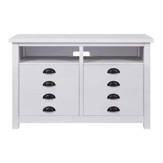
Granary Modern Farmhouse TV Console
If you have any questions regarding assembly or if parts are missing, DO NOT return this item to the
store where it was purchased. Please call our customer service number and have your instructions and
parts list ready to provide the model name, part name or factory number:
Or visit our web site 24 hours a day, 7 days a week for product assistance at
THIS INSTRUCTION BOOKLET CONTAINS IMPORTANT SAFETY INFORMATION.
Stock # BHW-10032 Rustic gray
ADULT ASSEMBLY REQUIRED
Pacific Standard Time: 8:30 a.m. - 4:30 p.m., Monday - Friday
Or e-mail your request to parts@whalenfurniture.com
PLEASE READ AND KEEP FOR FUTURE REFERENCE.
Date 2019-10-18
BHW-10033 White
866-942-5362
www.whalenstyle.com
Rev. 0001-A
LOT NUMBER:
DATE PURCHASED:
/
/
Advertisement

Related Manuals for Whalen Furniture Better Homes & Gardens BHW-10032


Summary of Contents for Whalen Furniture Better Homes & Gardens BHW-10032
- Page 1 LOT NUMBER: DATE PURCHASED: Granary Modern Farmhouse TV Console Stock # BHW-10032 Rustic gray BHW-10033 White ADULT ASSEMBLY REQUIRED If you have any questions regarding assembly or if parts are missing, DO NOT return this item to the store where it was purchased. Please call our customer service number and have your instructions and parts list ready to provide the model name, part name or factory number: 866-942-5362 Pacific Standard Time: 8:30 a.m.
- Page 2 M A X I M U M R E C O M M E N D E D W E I G H T L O A D S MANUFACTURER: Whalen Furniture Manufacturing CATALOG: Granary Modern Farmhouse TV Console MODEL # BHW-10032 / BHW-10033 MADE IN VIETNAM FITS UP TO MOST 139.7 cm / 55”...
- Page 3 IMPORTANT Before you begin: Open, identify and count all parts prior to assembly. Lay out parts on a flat and non-abrasive surface. You will need the parts identified on page 4 and 5 of this instruction manuals. NOTE: IT IS VERY IMPORTANT TO USE GLUE WITH DOWELS. EXCESS GLUE CAN BE WIPED OFF WITH DAMP CLOTH.
- Page 4 Parts and Hardware List Please read completely through the instructions and verify that all listed parts and hardware are present before beginning assembly. A- Top Panel (Qty. 1) B- Left Side Frame (Qty. 1) C- Right Side Frame (Qty. 1) D- Left Fixed Shelf (Qty.
- Page 5 Parts and Hardware List Please read completely through the instructions and verify that all listed parts and hardware are present before beginning assembly. (1) Cam Lock (2) Cam Bolt (3) M8 x 30 mm Wood Dowel (Qty. 27+1 extra) (Qty. 27+1 extra) (Qty.
- Page 6 Assembly Instructions ② x 23 1. Unpack the unit and confirm that you have all the hardware and required parts listed. Assemble the unit on a carpeted floor or the empty carton to avoid any scratch. 2. Securely screw the Cam Bolts (2) into the designated small holes on the Top Panel (A), Left Side Frame (B), Right Side Frame (C), Partition Molding (H) and Bottom Front Molding (J) using a Phillips screwdriver.
- Page 7 Assembly Instructions ② x 4 3. Securely screw two Cam Bolts (2) into the designated small holes on one face of Partition Panel (G). 4. Repeat the same procedure to screw another two Cam Bolts (2) on the other face of Partition Panel (G).
- Page 8 Assembly Instructions ⑤ x 4 ⑦ x 2 5. With the pilot holes as a guide, fasten one Door Stopper (7) to the Left Fixed Shelf (D) using two 15 mm Flat Head Screws (5). 6. Repeat the same procedure to attach the other Door Stopper (7) to the Right Fixed Shelf (E).
- Page 9 Assembly Instructions ③ x 2 7. Glue two Wood Dowels (3) into the inner holes of the Partition Panel (G). NOTE: It is very important to use a small amount of glue on both ends of dowels.
- Page 10 Assembly Instructions ① x 3 8. Align and attach the Partition Molding (H) to the Partition Panel (G) by engaging three Cam Locks (1). (Refer to page 3 on Cam Lock system operation supplement)
- Page 11 Assembly Instructions ③ x 12 9. Glue the Wood Dowels (3) into the inner holes of the Bottom Panel (F), Partition Panel (G) and Bottom Front Stretcher (J) as shown. NOTE: DO NOT insert the wood dowels into the cam bolts holes.
- Page 12 Assembly Instructions ④ x 2 10. Using the wood dowels as a guide, firmly press the Partition Panel (G) to the Bottom Panel (F) and fasten them in place with two 50 mm Screws (4). Fully tighten the screws with a Phillips screwdriver.
- Page 13 Assembly Instructions ① x 4 11. Attach the Bottom Front Stretcher (J) to the Bottom Panel (F) with four Cam Locks (1).
- Page 14 Assembly Instructions ③ x 12 12. Glue the Wood Dowels (3) into the inner holes of the Left Side Frame (B), Right Side Frame(C), Left Fixed Shelf (D) and Right Fixed Shelf (E) as shown.
- Page 15 Assembly Instructions ① x 4 13. Attach the Fixed Shelves (D and E) to the Partition Panel (G) by engaging two Cam Locks (1) repectively.
- Page 16 Assembly Instructions ① x 10 14. Align and attach the Side Frames (B and C) to previous assembly with ten Cam Locks (1).
- Page 17 Assembly Instructions ③ x 2 15. Glue two Wood Dowels (3) into the inner holes of the Top Front Stretcher (I) as shown.
- Page 18 Assembly Instructions ⑫ 16. Fasten the Top Front Strethcer (I) to the Top Panel (A) with four 38 mm Screws (12).
- Page 19 Assembly Instructions ① x 6 17. Place the Top Panel (A) onto the inserted Wood Dowels (3) on the vertical panels properly and fasten it in place with six Cam Locks (1).
- Page 20 Assembly Instructions 18. Securely screw the Support Foot (Q) into the threaded insert on the Bottom Panel (F) and set the floor leveler to the correct height.
- Page 21 Assembly Instructions ⑥ x 28 19. Now, go back and securely tighten all the cam locks and screws. Make sure that all the parts are tight and there are no gaps between the parts. This will help keep the unit square. 20.
- Page 22 Assembly Instructions x 16 ⑩ 23. Ask for assistance to lift the assembly unit upright and position it near the final location. 24. Pick up the Left Door (M) and attach the extended Hinge Arms to the Hinge Bases installed on the Left Side Frame (B).
- Page 23 Assembly Instructions ⑧ x 17 ⑨ 28. Insert four Shelf Pins (8) into the holes at the desired height inside each lower compartment. Tilt and rest the Adjustable Shelves (K and L) onto the Shelf Pins (8). 29. Plug the Cam Lock Covers (9) onto the visible cam locks to conceal the cams.
- Page 24 Assembly Instructions NOTE: To prevent your TV from tipping, you must install the Strip Stopper if you place your flat panel television directly on the console. Otherwise, skip to step 32. 30. Remove the paper backing of Stop Rail (R), then properly align the Stop Rail with the top edge of the stopper template on Top Panel (A).
- Page 25 Assembly Instructions Tools required (not included): Phillips screwdriver, stud finder, tape measure, pencil, power drill and 1/8” drill bit. 32. Ask for assistance to position the assembled unit at the desired location against a wall. If necessary, adjust the pre-attached Floor Levelers at the bottom of Side Frames (B and C) and Support Foot (Q) to level the unit.
-
Page 26: Care And Maintenance
Should this product be defective in workmanship or materials or fail under normal use, we will repair or replace it for up to one (1) year from date of purchase. Every Whalen Furniture product is designed to meet your highest expectations. We guarantee that you will immediately see the value of our fine furniture. - Page 27 NÚMERO de LOTE: FECHA de COMPRA: Consola para TV Granary Modern Farmhouse Modelo # BHW-10032 Gris rústico # BHW-10033 Blanco ENSAMBLE REQUERIDO POR ADULTO Si tienen alguna pregunta acerca del ensamble o si alguna parte está faltante, no retorne esté producto a la tienda donde lo compró.
- Page 28 M Á X I M O P E S O R E C O M E N D A D O FABRICANTE: Whalen Furniture Manufacturing CATALOGO: Consola para TV Granary Modern Farmhouse MODELO # BHW-10032 / BHW-10033 HECHO EN VIETNAM PARA LA MAYORÍA DE TV’S DE 139.7 cm /...
- Page 29 IMPORTANTE Antes de comenzar: Abra, identifique y cuente todas las partes antes del ensamble. Coloque las piezas sobre una superficie plana y no abrasiva. Tendrá que las partes identificadas en la página 4 y 5 de este manual de instrucciones. NOTA: ES MUY IMPORTANTE PARA EL USO DE PEGAMENTO CON LAS CLAVIJAS DE MADERA.
- Page 30 Lista de partes y material de ferretería Por favor lea completamente las instrucciones y verifique que estén todas las partes y partes de ferretería antes de iniciar el ensamblado. A- Panel superior (Cant. 1) B- Marco izquierdo (Cant. 1) C- Marco derecho (Cant. 1) D- Repisa fija izquierda (Cant.
- Page 31 Lista de partes y material de ferretería Por favor lea completamente las instrucciones y verifique que estén todas las partes y partes de ferretería antes de iniciar el ensamblado. (1) Tuerca de fijación (2) Perno de fijación (3) Clavija de madera M8 x 30 mm (Cant.
-
Page 32: Instrucciones De Ensamble
Instrucciones de ensamble ② x 23 1. Desempacar la unidad y confirmar que se tiene todo el material de ferretería y partes requeridas. Ensamblar la unidad en un piso alfombrado o en el cartón vacío para evitar rasguños. 2. Atornillar los pernos de fijación (2) en los agujeros pequeños designados en el panel superior (A), el marco izquierdo (B), el marco derecho (C), la moldura divisora (H) y el soporte inferior frontal (J) usando el desarmador estrella. - Page 33 Instrucciones de ensamble ② x 4 3. Atornillar 2 pernos de fijación (2) en los agujeros pequeños designados en una cara del panel divisor (G). 4. Repetir el mismo procedimiento para atornillar otros 2 pernos de fijación (2) en la otra cara del panel divisor (G).
- Page 34 Instrucciones de ensamble ⑤ x 4 ⑦ x 2 5. Con los agujeros pilotos como guía, sujetar un tope de puerta (7) a la repisa fija izquierda (D) usando 2 pernos cabeza plana de 15 mm (5). 6. Repetir el mismo procedimiento para adjuntar el otro tope de puerta (7) a la repisa fija derecha (E)
- Page 35 Instrucciones de ensamble ③ x 2 7. Pegar con pegamento 2 clavijas de madera (3) en los agujeros internos del panel divisor (G). Nota: Usar una cantidad pequeña de pegamento en ambos lados de las clavijas.
- Page 36 Instrucciones de ensamble ① x 3 8. Alinear y adjuntar la moldura divisora (H) al panel divisor (G) empleando 3 tuercas de fijación (1). (Consulte la página 3 del sistema de tuerca de fijación).
- Page 37 Instrucciones de ensamble ③ x 12 9. Pegar con pegamento las clavijas de madera (3) en los agujeros internos del panel inferior (F), del panel divisor (G) y en el soporte inferior frontal (J) como se muestra. NOTA: NO insertar las clavijas de madera en los agujeros de los pernos de fijación.
- Page 38 Instrucciones de ensamble ④ x 2 10. Usando las clavijas de madera como guía, presionar el panel divisor (G) al panel inferior (F) y sujetar en su lugar con 2 pernos de 50 mm (4). Apretar los pernos con el desarmador estrella.
- Page 39 Instrucciones de ensamble ① x 4 11. Adjuntar el soporte inferior frontal (J) al panel inferior (F) con 4 tuercas de fijación (1).
- Page 40 Instrucciones de ensamble ③ x 12 12. Pegar con pegamento las clavijas de madera (3) en los agujeros internos del marco izquierdo (B), del marco derecho (C), de la repisa fija izquierda (D) y de la repisa fija derecha (E) como se muestra.
- Page 41 Instrucciones de ensamble ① x 4 13. Adjuntar las repisas fijas (D y E) al panel divisor (G) empleando 2 tuercas de fijación (1).
- Page 42 Instrucciones de ensamble ① x 10 14. Alinear y adjuntar los marcos laterales (B y C) al ensamble previo con 10 tuercas de fijación (1).
- Page 43 Instrucciones de ensamble ③ x 2 15. Pegar 2 clavijas de madera (3) en los agujeros internos del soporte superior frontal (I) como se muestra.
- Page 44 Instrucciones de ensamble ⑫ 16. Sujetar el soporte superior frontal (I) al panel superior (A) con 4 pernos de 38 mm (12).
- Page 45 Instrucciones de ensamble ① x 6 17. Poner el panel superior (A) en las clavijas de madera insertadas (3) en los paneles verticales y sujetar en su lugar con 6 tuercas de fijación (1).
- Page 46 Instrucciones de ensamble 18. Atornillar la pata de soporte (Q) en los insertos roscados en el panel inferior (F) y ajustar el nivelador de piso a la altura correcta.
- Page 47 Instrucciones de ensamble ⑥ x 28 19. Ahora, volver y apretar todas las tuercas y los pernos de fijación. Asegurar que todas las partes estén apretadas y que no hay espacios entre las partes. Esto ayudara a mantener la unidad cuadrada. 20.
- Page 48 Instrucciones de ensamble x 16 ⑩ Pedir asistencia para levantar la unidad de ensamble en posición vertical y cerca del lugar final. Tomar la puerta izquierda (M) y adjuntar el brazo de bisagra extendido a las bases de bisagras instaladas en el marco izquierdo (B).
- Page 49 Instrucciones de ensamble ⑧ x 17 ⑨ 28. Insertar 4 pernos de repisa (8) en los agujeros a la altura deseada adentro de cada compartimiento inferior. Inclinar y descansar las repisas ajustables (K y L) sobre los pernos de repisa (8). 29.
- Page 50 Instrucciones de ensamble NOTA: Para prevenir que la TV se incline, debe instalar el tope acrílico de TV si pone su televisión de pantalla plana directamente sobre la consola. Por el contrario, saltar al paso 32. 30. Retirar el respaldo de papel del riel tope (R), luego alinear el riel tope con el borde superior del templado del tope en el panel superior (A).
- Page 51 Instrucciones de ensamble Herramientas requeridas (no incluidas): Desarmador estrella, localizador de barrotes, cinta métrica, lápiz, taladro y broca de 1/8”. 32. Pida asistencia para posicionar la consola ensamblada en el lugar deseado contra la pared. Si fuera necesario, ajustar los niveladores de piso pre-adjuntados en la parte inferior de los marcos laterales (B y C) y en la pata soporte (Q) para nivelar la unidad.
-
Page 52: Mantenimiento Y Cuidados
GARANTÍA DE CALIDAD Nosotros estamos seguros que usted se encontrará feliz con la compra de esté producto de Whalen Furniture. Si esté producto tiene algun defecto de ensamble o material, o si tiene alguna falla en uso normal, nosotros lo repararemos o lo re-emplazaremos hasta por un año a partir de la fecha de compra.
Need help?
Do you have a question about the Better Homes & Gardens BHW-10032 and is the answer not in the manual?
Questions and answers