
Subscribe to Our Youtube Channel
Related Manuals for Whalen Furniture Threshold Southwick Farmhouse A80524-A3


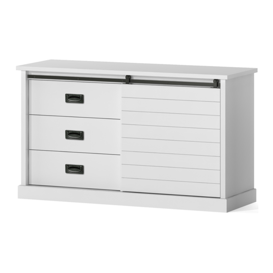
Summary of Contents for Whalen Furniture Threshold Southwick Farmhouse A80524-A3
- Page 1 Southwick Farmhouse 3 Drawer/Shelf Dresser with Sliding Barn Door-White Style # A80524-A3 DPC-item # 249-09-1432 >> Assembly instructions...
-
Page 2: Before You Begin
Congratulations on your latest Target purchase. Now what? Don’t start sweating over this box of parts. This will be easy. We did the hard work for you. All you need to do is follow our simple instructions and you’ll be on your way to transforming your room in no time. Good luck –... - Page 3 table of contents Introduction Hardware Parts list How to use the cam lock system Assembly 7-25 Care and maintenance and warranty Important safety information Serious or fatal crushing injuries can occur from furniture tip-over. To help prevent tip-over: • Install tip-over restraint provided. •...
- Page 4 hardware (H1) x 26 (H2) x 15 (H3) x 26 (H4) x 25 (H5) x 18 large cam lock small cam lock large cam bolt M8 x 30 mm wood dowel M6 x 20 mm wood dowel (H9) x 2 (H6) x 2 (H7) x 19 (H8) x 8...
- Page 5 ITEM DESCRIPTION QUANTITY Top panel Top front stretcher with hanging bar Left side panel Right side panel Partition panel Drawer front Drawer left side Drawer right side Drawer back panel Drawer bottom panel Bottom panel Bottom back stretcher Bottom front stretcher Adjustable shelf Back panel Barn door...
-
Page 6: How To Use The Cam Lock System
how to use the cam lock system... - Page 7 step 1. (H14) x 15 small cam bolt Screw-in cam bolts must be screwed down flush.
- Page 8 step 2. (H5) x 2 M6 x 20 mm wood dowel (H7) x 4 M4 x 25 mm screw The grooves line up with each other and face inward Attach one drawer back panel (I) between the drawer side panels (G and H).
- Page 9 step 3. The cam lock faces backward (H5) x 1 M6 x 20 mm wood dowel (H7) x 1 M4 x 25 mm screw Attach one drawer bottom support (Q) to the drawer back panel (I).
- Page 10 step 4. Slide one drawer bottom panel (J) into the grooves between the drawer side panels (G and H) until fully inserted into the groove of the drawer back panel (I).
- Page 11 step 5. (H2) x 5 (H5) x 3 small cam lock M6 x 20 mm wood dowel Attach one drawer front (F) to the drawer side panels (G and H) and drawer bottom support (Q). Note: Make sure that the drawer bottom panel (J) fits securely into the groove of the drawer front. Repeat the same process to assemble the other 2 drawers.
- Page 12 step 6. (H3) x 26 large cam bolt Screw-in cam bolts must be screwed down flush.
- Page 13 step 7. (H1) x 4 (H4) x 3 large cam lock M8 x 30 mm wood dowel The notch for side panel front molding Attach the bottom front stretcher (M) to the front edge of bottom panel (K). NOTE: There are two notches on the front edge.
- Page 14 step 8. The cam locks face inward (H1) x 4 (H4) x 3 large cam lock M8 x 30 mm wood dowel Attach the bottom back stretcher (L) to the bottom panel (K).
- Page 15 step 9. The right-angle side is located against the bottom front stretcher (H12) x 1 (H6) x 2 metal bracket M3.5 x 15 mm screw Using the pilot holes as a guide, attach the metal bracket (H12) to the bottom panel (K).
- Page 16 step 10. The notch and the front stretcher point in the same direction (H4) x 2 M8 x 30 mm wood dowel (H9) x 2 M4 x 50 mm screw Attach the partition panel (E) to the bottom panel (K).
- Page 17 step 11. (H1) x 8 (H4) x 8 large cam lock M8 x 30 mm wood dowel Attach the bottom panel assembly and top front stretcher with hanging bar (B) between the side panels (C and D).
- Page 18 step 12. Stand the previous assembly upright. Hook two rollers onto the pre-attached hanging bar on the top front stretcher (B). Take the bar door (P) and make sure that the bottom groove fit onto the installed metal bracket (H12) on bottom panel (K) properly.
- Page 19 step 13. (H1) x 10 (H4) x 9 large cam lock M8 x 30 mm wood dowel Attach top panel (A) to the vertical panels (C, D and E) and the top front stretcher (B).
- Page 20 step 14. (H7) x 4 M4 x 25 mm screw Flip around the assembled unit at its front edge. Fasten the side panel moldings to the bottom front stretcher (M).
- Page 21 step 15. NOTE: Go back and tighten all cam locks and screws before attaching the back panel. Make The adhesive tape faces outward sure that all the parts are tight and there are no gaps between the pieces. (H10) x 24 M3.5 x 15 mm screw Unfold the back panel (O) and align its holes with the pilot holes on the back edge of top panel (A).
- Page 22 step 16. (H8) x 8 (H11) x 8 M3.5 x 12 mm screw shelf pin Ask for assistance to lift the unit upright. Insert the shelf pins into the desired holes in the right compartment, make sure you place the four shelf pins in the same level so the shelf is not tilted. Tilt and rest adjustable shelves (N) onto shelf pins (H11) and secure them into place with 12mm screws (H8).
- Page 23 step 17. Ball bearing cart Ball bearing cart Release lever Release lever Drawer installation Insert the assembled drawers into the frame.
- Page 24 step 18. (H13) x 4 rubber bumper Stick the rubber bumpers (H13) to the barn door (P) where they will meet the side panels (C and D).
- Page 25 step 19. Wooden stud Wall Short screw Nylon strap Wall (H15) x 2 tipping restraint hardware kit Long screw Metal bracket Floor leveler Tools required: Phillips screwdriver, stud finder, measure tape, pencil, power drill and 1/8” drill bit. Adjust the pre-attached floor levelers to level the unit against a wall. Follow the instructions printed on plastic bag containing tipping restraint hardware to attach tip-over restraint between the unit and wall.
-
Page 26: Care And Maintenance
Should this product be defective in workmanship or materials or fail under normal use, we will repair or replace it for up to one (1) year from date of purchase. Every Whalen Furniture product is designed to meet your highest expectations. We guarantee that you will immediately see the value of our fine furniture. - Page 27 The maximum recommended weight allowance is 45.4 kg / 100 lb for top surface. The maximum recommended weight allowance is 13.6 kg / 30 lb for drawer. The maximum recommended weight allowance is 22.7 kg / 50 lb for shelf. Death or serious injury may occur when children climb on audio and/or video equipment furniture.
- Page 28 © 2018 Target. The Bullseye Design is a trademark of Target Brands, Inc. All rights reserved.
Need help?
Do you have a question about the Threshold Southwick Farmhouse A80524-A3 and is the answer not in the manual?
Questions and answers