
Related Manuals for FLYFINE FH-3600S


Summary of Contents for FLYFINE FH-3600S
- Page 1 User Manual Single Phase Hybrid Inverter Model: FH-3600S/FH-4600S/FH-5000S User Manual...
-
Page 2: Table Of Contents
Contents User Manual User Manual flyfine Information of the Manual 1. Notes On This Manual 1.1 Clarification 1.2 Additional Information 1.1 Clarifica 1.3 Storage of the Manual 1.4 Symbol Description This m anual p rovides instruc ons f or the a ssembly, i nstalla on, c ommissioning, 1.5 Warning symbols... -
Page 3: Symbol Description
User Manual User Manual flyfine flyfine Dangerous S ignal! WARNING: This s ymbol indicates a d angerous s itua on WARNING Risk of e lectric s hock! The i nstalla on o pera on c an o nly that, i f n ot avoided, c ould result in d eath o r s erious injury. -
Page 4: Dc And Ac Breaker
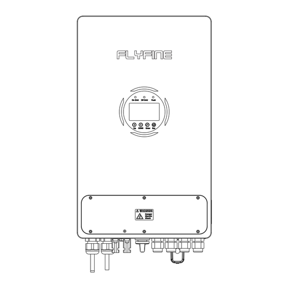
Do not a t to open the de vice during opera 3.1 Inverter Overview ( Mode: FH-3600S/FH-4600S/FH-5000S ) Overview ( See Figure 1 ) 2.2 DC and AC Breaker Disconnec ng t he u nit securely f rom t he g rid, t he P V g enerators, a nd b a eries by u sing D C and AC breaker. -
Page 5: Inverter Storage
User Manual User Manual flyfine flyfine 3.2 Unit Informa 3.3 Inverter Storage • The u nit is b idirec onal, which i s s uitable f or PV s ystem with b a ery s torage. • The u nit m ust b e s tored in its o riginal p ackaging. - Page 6 User Manual User Manual flyfine flyfine 3.5 Installa 3.6 Basic installa equirements These a re g uidelines f or the i nstaller to s elect a s uitable loca on f or installa on, i n order to a void p oten al damages to t he d evice a nd o perators.The u nit m ust b e Danger to life due to fire or explosion...
- Page 7 User Manual User Manual flyfine flyfine • Although t he e lectrical components o f t he i nverter a re rated IP65, i t is Roof 40CM recommended to a void p rolonged e xposure t o s unlight, rain a nd s now in t he installa on e nvironment, a s s hown in F igure 5 .
- Page 8 User Manual User Manual flyfine flyfine • Using t he m oun ng f rame a s a t emplate, a nd d rill holes a s s hown in F igure 9 . • A er c onfirming t hat the i nverter is fi rmly fi xed, i nsert and lock the t wo M 4...
-
Page 9: Inverter System Diagram
AC BREAKER LOAD AC The c urrent specifica ons o f the AC leakage s witch a re a s f ollows: Figure 12 Model FH-3600S FH-4600S FH-5000S Minimum current (A) Ensure that all cables are properly selected and installed in... - Page 10 The maximum output po wer of EPS is 4500w for circuit c urrent of t he p hotovoltaic b a ery p ack should b e less than t he FH-5000S and FH-4600S, and 3600W for FH-3600S. If the maximum D C c urrent of the i nverter.
- Page 11 User Manual User Manual flyfine flyfine 3.7.5 CT (Current Transducer) or ammeter connected to inverter • Connec ng t he b a ery with a s uitable c able i s important for s afe a nd effcient system o pera on. To reduce t he risk of injury, u se t he recommended c able s ize.
-
Page 12: Wi-Fi/Gprs
User Manual User Manual flyfine flyfine 4. Communica 4.3 Guidelines for Parallel and Group Three-phase Opera Note: Parallel opera ated with the help o f our monitoring server (please 4.1 Wi-Fi/GPRS contact your supplier to ob tain access). Hybrid inverters typically use Wi-Fi or GPRS as a standar d wireless communica... - Page 13 User Manual User Manual flyfine flyfine (2) Set the communica on address. The m aster inverter s hould b e s et to t he • A er c omple ng t he wiring o f the p ower w ire a nd c ommunica on w ire, you...
- Page 14 User Manual User Manual flyfine flyfine (3) Enable the p arallel func on. For g roup three-phase connec ons, p lease refer to the images below: NOTE: Each inverter m ust b e c onnected to a s eparate e nergy s torage b a ery.
- Page 15 User Manual User Manual flyfine flyfine (3) Enable the g roup three-phase f unc on. Master slav Set up Mailing address Set up Master slav Set up Mode Enable Set up Mailing address Set up Phase number Set up Mode Enable...
-
Page 16: Lcd Display
User Manual User Manual flyfine flyfine 5. LCD Display 5.1 LED indicators and their r e status Grid c Off-grid Warning light Status status (blue) status (blue) (red) 2023/07/19 17:03:16 On-grid always on or on-grid flashing 1.41kW 1.66kW Off-grid always on or off-grid flashing... - Page 17 User Manual User Manual flyfine flyfine 5.2.2 5.2.4 Advanced Se In "Advanc , press “ E nter ” and fill in the passw ord from the supplier to On the main in terface, press the “ U p ” key to en ter the main menu in terface, which enter the submenu in terface.
- Page 18 Set Value I. BAT Factory: BMS Protoc This parameter is used to set the communica y default.) protocol of the ba management system(BMS) for the inverter. (0: FLYFINE CAN; 1: PYLON CAN) Enter 1. Enable j. Float V Se This parameter is used to set the floa t charge voltage for the ba 2.
-
Page 19: Turn On/Off The Inverter
User Manual User Manual flyfine flyfine 5.2.6 Energy sta 5.2.7 Event informa Press " Enter " to ac cess the submenu in terface, where the f ollowing 4 op will In the e vent informa ess " Enter " to ac cess the submenu in terface,... -
Page 20: Inverter Cleaning
User Manual User Manual flyfine flyfine 7.2 Inverter cleaning Priority order: Load > Ba ery > Grid If the surface of the inverter is dirty, please turn off the inverter before cleaning the shell. Sufficient PV energy 7.3 DC S witch I... -
Page 21: Technical Parameters
User Manual User Manual flyfine flyfine Priority order: Load > Grid > Ba ery Model FH-5000S FH-4600S FH-3600S Sufficient PV energy AC Output Data (Back-up) Back-up N ominal Apparent Power (W) 4500W 4500W 3600W Nominal Output Voltage (V) 230V Nominal Output Freqency (Hz)
Need help?
Do you have a question about the FH-3600S and is the answer not in the manual?
Questions and answers