Table of Contents
Advertisement
Quick Links
Advertisement
Table of Contents

Related Manuals for FLYFINE FO-3000


Summary of Contents for FLYFINE FO-3000
- Page 1 User Manual Off Grid Single Phase Inverter Model: FO-3000/FO-5000 User Manual...
-
Page 2: Table Of Contents
Contents User Manual User Manual flyfine Information of the Manual Information on this Manual Introduction Features Validity Installation This manual is valid for the following devices: Mounting the Unit ► F0-3000/ FO-5000 Lead-acid Battery Connection Scope Lithium Battery Connection This manual describes the assembly, installation, operation and troubleshooting ofthis unit. Please read AC Input/Output Connection this manual carefully before installations and operations. -
Page 3: Introduction
User Manual User Manual flyfine flyfine Turning offthe unit will not reduce this risk. Features 9. NEVER charge a frozen battery. 10. For optimum operation ofthis inverter, please follow required specification to select appropriate cable Rated power 5KW, power factor 1 ►... -
Page 4: Installation
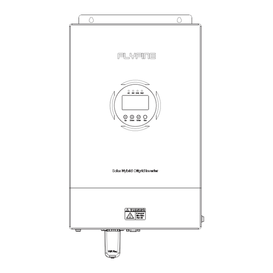
User Manual User Manual flyfine flyfine 1.AC input 2. Circuit breaker 3. AC output 4. Parallel 1 5. WIFI 6.USB 7. BMS 8. Parallel 2 9. Battery+ 10. Battery- 11. PV input 12. Power on/off switch 13. Status indicator 14. LCD display 15. -
Page 5: Lead-Acid Battery Connection
Wire Size Cable (mm2) Torque value (max) breaker/disconnector, be sure positive (+) must be connected to positive (+) and FO-3000/ FO-5000 1 x 4AWG 2-3 Nm negative (-) must be connected to negative (-)。 Note: For lead acid battery, the recommended charge currentis 0.2C(C= battery capacity) -
Page 6: Lithium Battery Connection
Suggested cable requirement for AC wires Model Gauge Cable (mm Torque Value FO-3000/ FO-5000 10 AWG 1.2-1.6 Nm Note: If choosing lithium battery, make sure to connectthe BMS communication cable between the battery and the inverter. You need to choose battery type as ''lithium battery". -
Page 7: Pv Connection
PV module connection. To reduce risk of injury, please use the proper connection. To reduce risk of injury, please use the proper recommended cable size as below Six inverters in parallel: Model Wire Size Cable (mm Torque value (max) FO-3000 1 x 8AWG 1.2-1.6 Nm FO-5000 1 x 12AWG 1.2-1.6 Nm PV Module Selection: When selecting proper PV modules, please be sure to consider below parameters: 1. -
Page 8: Parallel Operation In Three Phase
User Manual User Manual flyfine flyfine Parallel Operation in Three Phase Two inverters in one phase and only one inverter for the remaining two phases: WARNING Each machine needs to calibrate the inverter output voltage, DC voltage and battery voltage. Theoretically, the more calibration, the better, but at least the inverter output voltage and battery voltage calibration deviation are within ±... - Page 9 User Manual User Manual flyfine flyfine Three inverters in one phase and only one inverter for the remaining two phases: Three inverters in one phase, two inverters in the second phase and one inverter for the third phase: BAT+ BAT+...
-
Page 10: Operation
User Manual User Manual flyfine flyfine 1.1 Four-button function Operation The keys Functional specifications Function setting: Press ENTER key on the display page for more than 2 seconds to enter the function setting page. After entering Function Setting / the setting interface, press UP or DOWN key to turn the page up Identifying key and down to select the interface to be set. -
Page 11: Lcd Function Display
User Manual User Manual flyfine flyfine 1.1.3 LCD Function Display Working mode display area: After starting for 4 seconds, this display area mainly displays the working mode ofthe inverter. For example, standby mode, utility grid mode, battery mode, and Fault mode. -
Page 12: Operations In Fault Mode
User Manual User Manual flyfine flyfine 1.2.5 Operations in Fault Mode Page 3: Battery information is displayed, showing the battery voltage and charging current, as shown in Itindicates thatthe inverter is working in fault mode when the inverter buzzer is always ringing and the Figure 1-5 LED faultindicator is always on. - Page 13 User Manual User Manual flyfine flyfine Display page 6: Output Information is displayed, showing the output voltage and active power, as Display page 9: The software version ofthe inverter is displayed, as shown in Figure 1-11 shown in Figure 1-8...
- Page 14 User Manual User Manual flyfine flyfine Display page 15: Lithium battery capacity; The rated capacity is displayed on the upper left and the Display page 12: Lithium battery networking status; For SIG constant, the battery pack is in single current capacity displayed on the upper right. The upper left and right show the flashing ERR when group operation;...
-
Page 15: Function Setting Operations
User Manual User Manual flyfine flyfine seconds to automatically turn back to the main display page). 1.4 Function Setting Operations Note: The output voltage must be derated to 90% ifthe output voltage is setto 208V. Function setting operation ofinverter: Enter the exitfunction setting page and the operations details are as below: 1.4.2 Setting Other Functions... - Page 16 User Manual User Manual flyfine flyfine 1.4.2.3 Output Mode (MOD) 1.4.2.5 Grid Charging Current (RCC) Figure 1-15 Setting the output mode Figure 1-17 Setting the grid maximum charging current Function description: Setthe inverter output mode. Function description: Setthe grid maximum rechargeable current ofthe inverter.
- Page 17 User Manual User Manual flyfine flyfine Function Description: Return to the main screen. 1.4.2.10 Main Input Power Failure (MIP) Setting conditions: All status can be set. Description: The default setting is ON. In the function setting operation, ifitis setto ON, the page is notin the first interface (P1) atthis time, and will return to the firstinterface after 1min;...
- Page 18 User Manual User Manual flyfine flyfine 1.4.2.12 Transition from Overload to Bypass Mode (OLG) 1.4.2.14 Battery Return to Grid Voltage Point (BTG) Figure 1-24 Setting the transition from overload to bypass mode Figure 1-26 Switching the battery back to the grid voltage point Function description: Set whether to switch to grid mode immediately (also known as bypass mode) when itis overloaded in battery mode.
- Page 19 User Manual User Manual flyfine flyfine shutdown for a low battery voltage. 1.4.2.17 Battery Low Voltage Point (bAL) Setting conditions: All status can be set. Description: BTB:Back To Battery The default value is 52V When itis setto FUL, the battery will be charged until itis fully charged before restarting in battery mode.
- Page 20 User Manual User Manual flyfine flyfine bAU:battery Under 1.4.2.20 Voltage Point Setting in Floating Charge Mode (bFL) This parameter cannot be set when the battery definition mode is AGM(lead-acid battery type) or FLD (water-injection battery type). The default value is 42V The battery shutdown point can be modified when the battery type is setto CUS(Customer Setting...
- Page 21 User Manual User Manual flyfine flyfine 1.4.2.23 Setting Low Power Discharging Time (LWD) Figure 1-32 Setting the low-voltage point of grid in inverter mode Figure 1-34 Setting the low-power discharging time Function Description: Setthe low voltage protection point of grid.
- Page 22 User Manual User Manual flyfine flyfine Description: PAM: Parallel operation mode. SRE:Soft Relay Enable The default single mode is SIG. Butit can be setto parallel mode (PAR) : 3P1 (R phase), 3P2 (S phase) Ifthe default value is OFF, the output switch is turned to on only when the inverter voltage rises to the and 3P3 (T phase) .
- Page 23 User Manual User Manual flyfine flyfine Description: voltage ofthe battery. The battery will remain in the equalization phase until the setting equalization time EQM:Equalization Mode ofbattery is up. The default value is OFF, and the function is disabled. Setto ON, the controller will enter the The default value is 60 minutes.
- Page 24 User Manual User Manual flyfine flyfine Description: grid by tracking the maximum power point when setto ON. After the function is turned on, an alarm EQI:Equalization interval 56 is generated, and the inverter no longer decides the operation logic according to the BMS In the float charging stage with balanced mode enabled, ifbattery connection is detected and the...
- Page 25 User Manual User Manual flyfine flyfine 1.4.2.38 Low SOC shutdown function (BSU) 1.4.2.36 Battery dual-output Duration (DBT) Figure 1-47 Low SOC Shutdown function setting page Figure 1-45 Battery dual-way output low-voltage shutdown point page Function description: Shutdown when low SOC is set.
-
Page 26: Fault And Alarm Description
User Manual User Manual flyfine flyfine 1.5 Fault and Alarm Description when the lithium battery SOC reaches the setting value Ifthe PBG priority is set and the grid power is normal. It can be setto OFF, and atthis time the inverter will no longer switch to battery mode from grid mode according to the SOC situation. -
Page 27: Alarm Description
User Manual User Manual flyfine flyfine Battery over Transfer to The battery voltage is above the In parallel mode, the input recoverable The fault Input Freq Transfer to voltage failure mode setting value voltage frequency of different unrecoverable The fault... -
Page 28: Specifications
Temperature Table 1 Line Mode Specifications charged value than the setting value Alarm: One fan is faulty INVERTER MODEL FO-3000 FO-5000 Fan Fault and another No fan speed signal is detected. recoverable The alarm Input Voltage Waveform Sinusoidal (utility grid or generator) - Page 29 Mode) Low DC Cut-off SOC(Li Mode) Default 20%, 5%~50% settable Table 4 General Specifications High DC Recovery Voltage 58Vdc (C.V. charging voltage) INVERTER MODEL FO-3000 FO-5000 High DC Cut-off Voltage 32Vdc 64Vdc Operating Temperature Range 0°C ~40 °C No Load Power Consumption <50W...
Need help?
Do you have a question about the FO-3000 and is the answer not in the manual?
Questions and answers