
Related Manuals for FLYFINE FH8000LV


Summary of Contents for FLYFINE FH8000LV
- Page 1 User Manual Three Phase Hybrid Storage Inverter(Lv) Model: FH8000LV/FH10000LV/FH12000LV User Manual...
-
Page 2: Table Of Contents
Contents Disclaimer User Manual User Manual Disclaimer 1. Introduction 1.1 Safety & Warning Thank you for choosing our products and services. Before using the product, please 1.2 Product Overview read carefully and fully understand this document to ensure that you can use the 2. -
Page 3: Introduction
User Manual User Manual flyfine flyfine 1. Introduction Read through the user manual before any operations. Hybrid inverter series, also called hybrid or bidirectional solar inverters, apply to solar system with participation of PV, battery, loads and grid system for energy management. -
Page 4: Product Overview
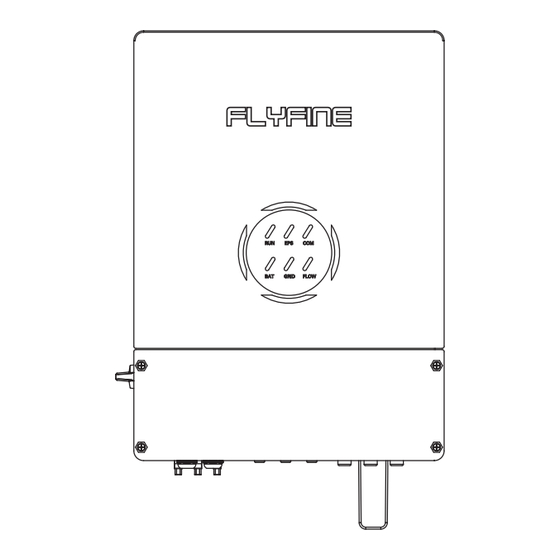
User Manual User Manual flyfine flyfine 1.2 Product Overview On = Grid Is Active And Connected Blink = Grid Is Active But Not Connected Panel Gen Port GRID Off = Grid Is Not Active Back-Up Port Battery Terminals On = Consuming Energy From Grid /Buying... -
Page 5: Packing List
User Manual User Manual flyfine flyfine 2.2 Packing List Rule 3. Ambient temperature should be lower than 60°C Rule 4. On receiving the inverter, please check to make sure all the components as below The installation of inverter should be protected under shelter from direct sunlight or bad weather like snow, rain, lightning etc. -
Page 6: Electrical Wiring Connection
User Manual User Manual flyfine flyfine 2.3.2 Installation 2.4 Electrical Wiring Connection 2.4.1 PV Connection This inverter can only be installed on a flat surface. Before connecting PV panels/strings to inverter, please make sure requirements are followed as below :... - Page 7 User Manual User Manual flyfine flyfine 2.4.2 Battery Connection Step3: Connect battery terminals onto inverter For lithium battery (pack) the capacity should be 100Ah or larger. Battery cable requirement as below. NOTE: Please make sure polarity (+/) of battery are not reversed...
- Page 8 User Manual User Manual flyfine flyfine 2.4.3 On-grid & Back-up Connection Step2: Lock terminal cover and screw up the terminal cap. An external AC switch (>32A) is needed for On-Grid connection to isolate from grid when necessary. Below are the requirements on AC switch use:...
- Page 9 User Manual User Manual flyfine flyfine CT Indications Step2: Lock terminal cover and screw up the terminal cap. All work should be performed by trained and qualified operators using safe and suitable tools. L1 L2 L3 N PE NOTE: Since this product is a split type transformer, please pay attention to the cleanliness Make sure the terminal cover is rightly of the magnetic core surface during installation.
- Page 10 User Manual User Manual flyfine flyfine System Connection Diagrams NOTE: Meter communication cable (RJ45) is attached on the inverter "To Meter" cable, could be extended to max 100m, and must use standard RJ45 cable and plug as below: Back-up Loads...
-
Page 11: Three Phase Parallel Connection Diagram
User Manual User Manual flyfine flyfine Three phase connection diagram 2.5 Three Phase Parallel Connection Diagram L wire N wire PE wire L wire N wire PE wire BMS 485 BMS CAN DRMs Inverter No.3 Parallel_1 Parallel_2 RS485 (slave) Ground... -
Page 12: Trouble Shooting
User Manual User Manual flyfine flyfine 3. Trouble Shootings System Warning Warning Description Solutions Event Code 2 3.1 Warning List 1. Check the battery voltage; System The battery voltage is 2. Check whether Battery cables are Warning Warning Description Solutions lower than 44V or lower firmly and correctly connected;... -
Page 13: Fault Reference Codes
User Manual User Manual flyfine flyfine 3.2 Fault Reference Codes Grid voltage fault The Grid Voltage is 1.Check the AC voltage is in the range of Higer than the standard voltage inspecification; System Over Ugrid setting value when 2.Check whether grid AC cables are firmly and... - Page 14 User Manual User Manual flyfine flyfine The inverter 1. check the power of the backup load; Reserved current is high and 2. Restart the inverter 2-3 times; XINT Iac touch the 3. if the fault still existing, please contact us for The BUS 1.
-
Page 15: Troubleshooting
User Manual User Manual flyfine flyfine System The upper Fault computer 1. Restart the inverter 2-3 times; Fault Event Description Solutions Over time SPI communicates 2. if the fault still existing, please contact Code 3 with the lower us for help. -
Page 16: Others
User Manual User Manual flyfine flyfine Problems During Operation Q. On App, some columns show NA, like battery SOH, etc. why is that? A. NA means App does not receive data from inverter or server, normally it is because Hybrid inverter not Start Up With ONLY Battery... -
Page 17: Technical Parameters
Non-isolated PV- AC Inverter Isolation High frequency isolated(Battery Side) 4.2 Technical Parameters Overvoltage category OVC III (AC Main), OVC II (PV) Dimensions,D*W*H(mm) 475*683*256 Model FH8000LV FH10000LV FH12000LV Weight(kg) PV Input Altitude 2000m Vmax PV (Vdc) (absolute Max.) 1000 V Isc PV (absolute Max.) (A) 22.5 A/22.5A...
Need help?
Do you have a question about the FH8000LV and is the answer not in the manual?
Questions and answers