
Related Manuals for FLYFINE FH8000T


Summary of Contents for FLYFINE FH8000T
- Page 1 User Manual Three Phase Hybrid Storage Inverter(HV) FH8000T/FH1000OT/FH12000T/FH15000T User Manual...
-
Page 2: Table Of Contents
Contents User Manual Disclaimer 1. About This Manual Thank you for choosing our products and services. Before using the product, please read carefully and fully understand this document to ensure that you can use the product 1.1 Peculiarity correctly. By using this product, you are deemed to have understood, recognized and 1.2 Applicable Model accepted all the terms and contents of this document, and the user undertakes to be 1.3 Target Audience... -
Page 3: About This Manual
User Manual User Manual flyfine flyfine 1.5 Symbol Explanation 1. About This Manual The EC series has been designed and tested strictly according to international safety This manual describes the product information, installation, electrical connection, regulations. Read all safety instructions carefully prior to any work and observe them commissioning, troubleshooting, and maintenance. -
Page 4: Safety Instructions
User Manual User Manual flyfine flyfine 2.1 General 2. Safety Instructions Never power on the inverter during installation. Please strictly follow these safety instructions in the user manual during the operation. Before installations, read through the user manual to learn about the product and the precautions. -
Page 5: Operation
User Manual User Manual flyfine flyfine 2.4 Operation 3. Product Introduction When the inverter is operating, do not disconnect under load. DANGER 3.1 Product Overview EC serial inverter is a bi-directional PV inverter with battery storage function which can The temperature of the inverter surface can exceed 60℃ during operation. Make convert solar energy to feed the AC grid or store energy into battery for future use. -
Page 6: System Diagram
User Manual User Manual flyfine flyfine 3.2 System Diagram 3.3 System Work Modes The EC serial hybrid inverter used to configure a residential grid-tied system. This system 3.3.1 Self-consumption mode consists of the PV string, grid-tied hybrid inverter, power distribution unit (PDU), and electricity meter. - Page 7 User Manual User Manual flyfine flyfine Night: 3.3.2 Economic Mode If the battery power is sufficient, the load will be powered by the battery. If the battery power is not enough, the load will be powered by the power grid.
- Page 8 User Manual User Manual flyfine flyfine 3.3.3 Backup Mode 3.3.4 Off-grid Mode The Backup mode can set different battery SOC values during grid connection Off Grid Mode After the setting is completed, the off-grid function of the inverter NOTICE ! and off grid.
-
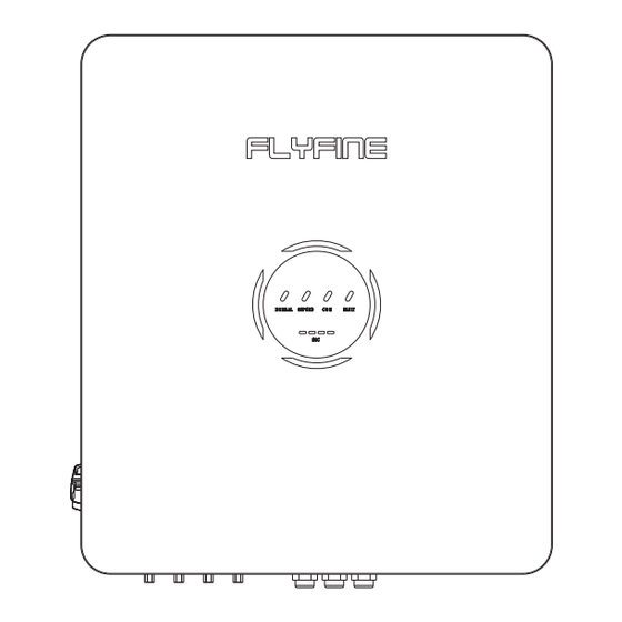
Page 9: Led Indicators
User Manual User Manual flyfine flyfine 3.4 LED Indicators 5. Installation The LED indicator on the front of the inverter can indicate the current working state of the inverter. 5.1 Check before Unpacking LED Indicator Status Description Check the following items after receiving the product. -
Page 10: Installation Requirements
User Manual User Manual flyfine flyfine 5.3 Installation Requirements 5.4 Mounting Angle 1. The inverter should be installed vertically or tilted no more than 15°. Installation Environment Requirements 2. Do not install the inverter on a forward-leaning or horizontal plane. -
Page 11: Mounting Clearance
User Manual User Manual flyfine flyfine 5.5 Mounting Clearance 5.7 Mounting Steps To secure good heat dissipation and easy dismantlement, the minimum clearance around the inverter should not be smaller than the below values. ≥300mm Upward -------- 300mm ≥500mm ≥500mm ≥300mm... -
Page 12: Electrical Connections
User Manual User Manual flyfine flyfine 6. Electrical Connections Avoid the water pipes and cables buried in the wall when drilling holes. Wear goggles and a dust mask to prevent the dust from being inhaled or NOTICE ! contacting eyes when drilling holes. -
Page 13: System Overviews
User Manual User Manual flyfine flyfine 6.2 System Overiews N and PE cables are separately wired in the Main Panel. Ensure that the grounding of BACK-UP is correctly and tightened. Otherwise, NOTICE ! the BACK-UP function may be abnormal in case of grid failure. -
Page 14: Installing Load/Off-Grid Terminals
User Manual User Manual flyfine flyfine 6.4 Installing Load/Off-Grid Terminals Step 1: Connecting the terminal to the PE cable Step 2: Use a multimeter to measure the voltage(Normal voltage≤850V, Max voltage≤1000V) Step 2: Connecting Load/Off-Grid Terminals Step 3: Connecting PV/Battery Terminals... -
Page 15: Connecting The Pe Cable
User Manual User Manual flyfine flyfine 6.5 Connecting the PE cable 6.6 Installing Meter The smart meter and CT have been preset parameters before delivered with The PE cable connected to the enclosure of the inverter cannot replace the PE cable connected to the AC output port. -
Page 16: Installing Wi-Fi Collector
User Manual User Manual flyfine flyfine Step 3: Key operation instruction Connecting Coupe circuit Address Baud rate 9600 Button Operation Selects the Voltage and Current display screens In Set-up Mode, this is the "Left" or "Back" button. Select the Frequency and Power factor display screens In Set-up Mode, this is the "Up"... -
Page 17: Connecting The Bms Communication Cable(Rj45 Connector)
User Manual User Manual flyfine flyfine 6.8 Connecting The BMS Communication Cable(RJ45 Connector) 6.9 Check Before Power ON The product is firmly installed at a clean place that is well-ventilated and NOTICE ! RJ45 connector with the following definition can be connected: easy-to operate. -
Page 18: Inverter Parameters
User Manual User Manual flyfine flyfine 7. Inverter Parameters MODEL FH8000T FH10000T FH12000T FH15000T Efficiency MODEL FH8000T FH10000T FH12000T FH15000T MPPT efficiency 99.90% Battery Input Data Max. efficiency 98.30% 98.40% Battery Type Lithium battery Euro-efficiency 97.50% 97.60% Protection 180-750 Battery Voltage Range(V)
Need help?
Do you have a question about the FH8000T and is the answer not in the manual?
Questions and answers