Advertisement
Quick Links
Advertisement

Related Manuals for Supermicro FatTwin F628R3-FT+


Summary of Contents for Supermicro FatTwin F628R3-FT+
- Page 1 ® FatTwin F628R3-FT+ F628R3-FTPT+ USER’S MANUAL Revision 1.0a...
- Page 2 This product, including software and documentation, is the property of Supermicro and/or its licensors, and is supplied only under a license. Any use or reproduction of this product is not allowed, except as expressly permitted by the terms of said license.
- Page 3 Preface Preface About This Manual This manual is written for professional system integrators and PC technicians. It provides information for the installation and use of the FatTwin™ F628R3-FT+/FTPT+. Installation and maintenance should be performed by experienced technicians only. The FatTwin F628R3-FT+/FTPT+ is a high-end server based on the F424AL-R1K28BP 4U rackmount chassis and a dual processor X10DRFF-iG/iTG serverboard.
- Page 4 FatTwin F628R3-FT+/FTPT+ User's Manual Chapter 5: Advanced Serverboard Setup Chapter 5 provides detailed information on the X10DRFF-iG/iTG serverboards, including the locations and functions of connections, headers and jumpers. Refer to this chapter when adding or removing processors or main memory and when reconfi...
- Page 5 FatTwin F628R3-FT+/FTPT+ User's Manual Notes...
- Page 6 Mounting Rails ....................1-6 Advanced Power Management ............... 1-6 Intel® Intelligent Power Node Manager (NM) ..........1-6 Manageability Engine (ME) ................1-6 Contacting Supermicro ..................1-8 FatTwin: System Notes ................... 1-9 Nodes ......................1-9 System Power ....................1-9 SAS/SATA Backplane/Drives ................1-9 Chapter 2 Server Installation Overview ......................
- Page 7 Table of Contents Rack Mounting Considerations ............... 2-3 Ambient Operating Temperature ..............2-3 Reduced Airfl ow ..................2-3 Mechanical Loading ................... 2-3 Circuit Overloading ..................2-3 Reliable Ground ..................2-4 Rack Mounting Instructions ................2-4 Identifying the Sections of the Rack Rails ............2-4 Adjusting the Rails ..................
- Page 8 FatTwin F628R3-FT+/FTPT+ User's Manual Chapter 5 Advanced Serverboard Setup Handling the Serverboard ................5-1 Precautions ..................... 5-1 Unpacking ....................... 5-1 Connecting Cables ..................5-2 Connecting Data Cables ................. 5-2 Control Panel Connectors and I/O Ports ............5-2 Processor and Heatsink Installation..............5-3 Installing a Passive CPU Heatsink ..............
- Page 9 Table of Contents Permanent and Optional Standoffs ............... 6-12 6-10 Installing Front and Rear Expansion Cards ..........6-14 PCI-E Slot Setup ................... 6-14 F424AL PCI-E Slot Confi gurations ............... 6-15 Installing a Front Low-Profi le Expansion Card ..........6-15 6-11 Installing the Air Shroud ................
- Page 10 FatTwin F628R3-FT+/FTPT+ User's Manual Notes...
- Page 11 One (1) F418/F424 rail set (MCP-290-41803-0N) Note: For your system to work properly, please follow the links below to download all necessary drivers/utilities and the user’s manual for your server. • Supermicro product manuals: http://www.supermicro.com/support/manuals/ • Product drivers and utilities: ftp://ftp.supermicro.com...
- Page 12 Data Transfer Rate of up to 9.6 GT/s per direction. Please refer to the serverboard description pages on our web site for a complete listing of supported processors (www.supermicro.com). Memory Each X10DRFF-iG/iTG serverboard node has sixteen (16) DIMM slots...
- Page 13 Gigabit or two 10GBased-T Ethernet ports. Note: For IPMI Confi guration Instructions, please refer to the Embedded IPMI Configuration User's Guide available at http://www.supermicro.com/support/ manuals/. Graphics Controller The X10DRFF-iG/iTG features an integrated Aspeed AST2400 BMC Controller for onboard graphics capability.
- Page 14 • RMCP+ protocol supported Note: For more information on IPMI confi guration, please refer to the IPMI User's Guide posted on our website at http://www.supermicro.com/support/manuals/. Power Supply Please connect the power cable from the SMC-Proprietary Adaptor (BPN-ADP- F418L) to the serverboard in order to provide power to the system.
- Page 15 The air shroud will differ for different motherboards. If using a serverboard which is not the default in the chassis, refer to the optional parts in the Appendix of this manual, or the Supermicro Web site at www.supermicro.com...
- Page 16 FatTwin F628R3-FT+/FTPT+ User's Manual Mounting Rails The F424AL includes a set of rails, and can be placed in a rack for secure storage and use. To setup your rack, follow the step-by-step instructions included in this manual. Advanced Power Management Intel®...
- Page 17 Chapter 1: Introduction Figure 1-1. Intel C612 Chipset: System Block Diagram Note: This is a general block diagram and may not exactly repre- sent the features on your serverboard. See the previous pages for the actual specifi cations of your serverboard. This block diagram is intended for your reference only.
- Page 18 Super Micro Computer, Inc. 980 Rock Ave. San Jose, CA 95131 U.S.A. Tel: +1 (408) 503-8000 Fax: +1 (408) 503-8008 Email: marketing@supermicro.com (General Information) support@supermicro.com (Technical Support) Website: www.supermicro.com Europe Address: Super Micro Computer B.V. Het Sterrenbeeld 28, 5215 ML...
- Page 19 Chapter 1: Introduction FatTwin: System Notes As a FatTwin confi guration, the FatTwin F628R3-FT+/FTPT+ is a unique server system. With four system boards incorporated into a single chassis acting as four separate nodes, there are several points you should keep in mind. Nodes Each of the four serverboards act as a separate node in the system.
- Page 20 FatTwin F628R3-FT+/FTPT+ User's Manual Notes 1-10...
- Page 21 Chapter 2: Server Installation Chapter 2 Server Installation Overview This chapter provides a quick setup checklist to get your FatTwin F628R3-FT+/FTPT+ up and running. Following these steps in the order given should enable you to have the system operational within a minimum amount of time. This quick setup assumes that your system has come to you with the processors and memory preinstalled.
- Page 22 FatTwin F628R3-FT+/FTPT+ User's Manual Warnings and Precautions Choosing a Setup Location • Leave enough clearance in front of the rack to enable you to open the front door completely (~25 inches) and approximately 30 inches of clearance in the back of the rack to allow for suffi...
- Page 23 Chapter 2: Server Installation Rack Mounting Considerations Warning! To prevent bodily injury when mounting or servicing this unit in a rack, you must take special precautions to ensure that the system remains stable. The following guidelines are provided to ensure your safety: •...
- Page 24 FatTwin F628R3-FT+/FTPT+ User's Manual Reliable Ground A reliable ground must be maintained at all times. To ensure this, the rack itself should be grounded. Particular attention should be given to power supply connections other than the direct connections to the branch circuit (i.e. the use of power strips, etc.).
- Page 25 Chapter 2: Server Installation Adjusting the Rails Each rail assembly has an adjusting screw. Loosening this screw allows you to adjust the length of the rail to fi t a variety of rack sizes. Figure 2-1: Identifying the Outer Rail and Inner Rails (Left Rail Assembly Shown) Inner Rail Outer Rail...
- Page 26 FatTwin F628R3-FT+/FTPT+ User's Manual Installing the Rails on a Rack Installing the Rails 1. Adjust the length of both rails as described on the previous page. 2. Align the front section of the outer rail with the slots on the front post of the rack.
- Page 27 Chapter 2: Server Installation Chassis Installation Installing the Chassis into a Rack 1. Confi rm that the rails are correctly installed on the rack. 2. Align the bottom of the chassis with the bottom of the rails. 3. Insert the chassis into the rails, keeping the pressure even on both sides, pushing the chassis into the rack.
- Page 28 FatTwin F628R3-FT+/FTPT+ User's Manual Checking the Serverboard Setup After you install the SuperServer F628R3-FT+/FTPT+ in the rack, you will need to open the unit to make sure the serverboard is properly installed and all the connections have been made. Accessing the inside of the System Before operating the server for the fi...
- Page 29 Chapter 2: Server Installation Checking the Drive Bay Setup Next, you should check to make sure the peripheral drives and the SATA drives have been properly installed and all connections have been made. Checking the Drives 1. All drives are accessible from the front of the server. A hard drive can be installed and removed from the front of the chassis without removing the top chassis cover.
- Page 30 FatTwin F628R3-FT+/FTPT+ User's Manual Notes 2-10...
- Page 31 Chapter 3: System Interface Chapter 3 System Interface Overview There are several LEDs on the control panel and on the drive carriers to keep you constantly informed of the overall status of the system. All F424AL models include control panels on the chassis which control each of the system nodes. This chapter explains the meanings of all LED indicators and the appropriate re- sponse you may need to take.
- Page 32 FatTwin F628R3-FT+/FTPT+ User's Manual • Power: The main power button on each of the four control panels is used to apply or remove power from the power supply to each of the four systems in the chassis. Turning off system power with this button removes the main power, but keeps standby power supplied to the system.
- Page 33 The following statements are industry standard warnings, provided to warn the user of situations which have the potential for bodily injury. Should you have questions or experience difficulty, contact Supermicro's Technical Support department for assistance. Only certifi ed technicians should attempt to install or confi gure components.
- Page 34 FatTwin F628R3-FT+/FTPT+ User's Manual Warnung WICHTIGE SICHERHEITSHINWEISE Dieses Warnsymbol bedeutet Gefahr. Sie befi nden sich in einer Situation, die zu Verletzungen führen kann. Machen Sie sich vor der Arbeit mit Geräten mit den Gefahren elektrischer Schaltungen und den üblichen Verfahren zur Vorbeugung vor Unfällen vertraut.
- Page 35 Warning Statements for AC Systems ﺟﺴﺪﯾﺔ اﺻﺎﺑﺔ ﺗﺘﺴﺒﺐ ﻓﻲ ﺣﺎﻟﺔ ﯾﻤﻜﻦ أن اﻧﻚ ﻓﻲ ﺧﻄﺮ ﯾﻌﻨﻲ ھﺬا اﻟﺮﻣﺰ !ﺗﺤﺬﯾﺮ اﻟﺪواﺋﺮ ﺑﺎﻟﻤﺨﺎطﺮ اﻟﻨﺎﺟﻤﺔ ﻋﻦ ﻦ ﻋﻠﻰ ﻋﻠﻢ ، ﻛ ﻣﻌﺪات ﺗﻌﻤﻞ ﻋﻠﻰ أي ﻗﺒﻞ أن اﻟﻜﮭﺮﺑﺎﺋﯿﺔ ﺣﻮادث أي وﻗﻮع ﻤﻨﻊ ﻟ اﻟﻮﻗﺎﺋﯿﺔ...
- Page 36 FatTwin F628R3-FT+/FTPT+ User's Manual Installation Instructions Warning! Read the installation instructions before connecting the system to the power source. 設置手順書 システムを電源に接続する前に、 設置手順書をお読み下さい。 警告 将此系统连接电源前,请先阅读安装说明。 警告 將系統與電源連接前,請先閱讀安裝說明。 Warnung Vor dem Anschließen des Systems an die Stromquelle die Installationsanweisungen lesen. ¡Advertencia! Lea las instrucciones de instalación antes de conectar el sistema a la red de alimentación.
- Page 37 Chapter 4: Warning Statements for AC Systems Circuit Breaker Warning! This product relies on the building's installation for short-circuit (overcurrent) protection. Ensure that the protective device is rated not greater than: 250 V, 20 A. サーキッ ト ・ ブレーカー この製品は、 短絡 (過電流) 保護装置がある建物での設置を前提としています。 保護装置の定格が250 V、...
- Page 38 FatTwin F628R3-FT+/FTPT+ User's Manual ﻓﻲ اﻟﺘﻲ ﺗﻢ ﺗﺜﺒﯿﺘﮭﺎ ﻣﻦ اﻟﺪواﺋﺮاﻟﻘﺼﯿﺮة اﻟﺤﻤﺎﯾﺔ ﻣﻌﺪات ﯾﻌﺘﻤﺪ ﻋﻠﻰ ھﺬا اﻟﻤﻨﺘﺞ اﻟﻤﺒﻨﻰ أﻛﺜﺮ ﻣﻦ ﻟﯿﺲ ﻮﻗﺎﺋﻲ اﻟ اﻟﺠﮭﺎز ﺗﻘﯿﯿﻢ أن ﺗﺄﻛﺪ ﻣﻦ 20A, 250V 경고! 이 제품은 전원의 단락(과전류)방지에 대해서 전적으로 건물의 관련 설비에 의존합니다. 보호장치의 정격이 반드시 250V(볼트), 20A(암페어)를 초과하지 않도록...
- Page 39 Chapter 4: Warning Statements for AC Systems Warnung Das System muss von allen Quellen der Energie und vom Netzanschlusskabel getrennt sein, das von den Spg.Versorgungsteilmodulen entfernt wird, bevor es auf den Chassisinnenraum zurückgreift, um Systemsbestandteile anzubringen oder zu entfernen. ¡Advertencia! El sistema debe ser disconnected de todas las fuentes de energía y del cable eléctrico quitado de los módulos de fuente de alimentación antes de tener acceso el interior del chasis para instalar o para quitar componentes de sistema.
- Page 40 FatTwin F628R3-FT+/FTPT+ User's Manual Equipment Installation Warning! Only trained and qualifi ed personnel should be allowed to install, replace, or service this equipment. 機器の設置 トレーニングを受け認定された人だけがこの装置の設置、 交換、 またはサービスを許可 されています。 警告 只有经过培训且具有资格的人员才能进行此设备的安装、更换和维修。 警告 只有經過受訓且具資格人員才可安裝、更換與維修此設備。 Warnung Das Installieren, Ersetzen oder Bedienen dieser Ausrüstung sollte nur geschultem, qualifi...
- Page 41 Chapter 4: Warning Statements for AC Systems Waarschuwing Deze apparatuur mag alleen worden geïnstalleerd, vervangen of hersteld door geschoold en gekwalifi ceerd personeel. Restricted Area Warning! This unit is intended for installation in restricted access areas. A restricted access area can be accessed only through the use of a special tool, lock and key, or other means of security.
- Page 42 FatTwin F628R3-FT+/FTPT+ User's Manual אזור עם גישה מוגבלת !אזהרה יש להתקין את היחידה באזורים שיש בהם הגבלת גישה. הגישה ניתנת בעזרת .('כלי אבטחה בלבד )מפתח, מנעול וכד ﻣﺤﻈﻮرة ﻣﻨﺎطﻖ ﻟﺘﺮﻛﯿﺒﮭﺎ ﻓﻲ ھﺬه اﻟﻮﺣﺪة ﺗﺨﺼﯿﺺ ﺗﻢ ،أداة ﺧﺎﺻﺔ ﻣﻦ ﺧﻼل اﺳﺘﺨﺪام ﻓﻘﻂ...
- Page 43 Chapter 4: Warning Statements for AC Systems Warnung Bei Einsetzen einer falschen Batterie besteht Explosionsgefahr. Ersetzen Sie die Batterie nur durch den gleichen oder vom Hersteller empfohlenen Batterietyp. Entsorgen Sie die benutzten Batterien nach den Anweisungen des Herstellers. Attention Danger d'explosion si la pile n'est pas remplacée correctement. Ne la remplacer que par une pile de type semblable ou équivalent, recommandée par le fabricant.
- Page 44 FatTwin F628R3-FT+/FTPT+ User's Manual Redundant Power Supplies Warning! This unit might have more than one power supply connection. All connections must be removed to de-energize the unit. 冗長電源装置 このユニッ トは複数の電源装置が接続されている場合があります。 ユニッ トの電源を切るためには、 すべての接続を取り外さなければなりません。 警告 此部件连接的电源可能不止一个,必须将所有电源断开才能停止给该部件供电。 警告 此裝置連接的電源可能不只一個,必須切斷所有電源才能停止對該裝置的供電。 Warnung Dieses Gerät kann mehr als eine Stromzufuhr haben. Um sicherzustellen, dass der Einheit kein trom zugeführt wird, müssen alle Verbindungen entfernt werden.
- Page 45 Chapter 4: Warning Statements for AC Systems اﻣﺪاد اﻟﻄﺎﻗﺔ ﺑﻮﺣﺪات ﻋﺪة اﺗﺼﺎﻻت ﺠﮭﺎز اﻟ ﯾﻜﻮن ﻟﮭﺬا ﻗﺪ اﻟﻜﮭﺮﺑﺎء ﻋﻦ ﻮﺣﺪة اﻟ ﻟﻌﺰل ﻛﺎﻓﺔ اﻻﺗﺼﺎﻻت ﯾﺠﺐ إزاﻟﺔ 경고! 이 장치에는 한 개 이상의 전원 공급 단자가 연결되어 있을 수 있습니다. 이 장치에 전원을...
- Page 46 FatTwin F628R3-FT+/FTPT+ User's Manual Attention Lorsque le système est en fonctionnement, des tensions électriques circulent sur le fond de panier. Prendre des précautions lors de la maintenance. מתח בפנל האחורי !הרה אז קיימת סכנת מתח בפנל האחורי בזמן תפעול המערכת. יש להיזהר במהלך .העבודה...
- Page 47 Chapter 4: Warning Statements for AC Systems ¡Advertencia! La instalacion del equipo debe cumplir con las normas de electricidad locales y nacionales.Attention L'équipement doit être installé conformément aux normes électriques nationales et locales. תיאום חוקי החשמל הארצי !אזהרה הציוד חייבת להיות תואמת לחוקי החשמל המקומיים והארציים התקנת...
- Page 48 FatTwin F628R3-FT+/FTPT+ User's Manual Warnung Die Entsorgung dieses Produkts sollte gemäß allen Bestimmungen und Gesetzen des Landes erfolgen. ¡Advertencia! Al deshacerse por completo de este producto debe seguir todas las leyes y reglamentos nacionales. Attention La mise au rebut ou le recyclage de ce produit sont généralement soumis à des lois et/ou directives de respect de l'environnement.
- Page 49 Chapter 4: Warning Statements for AC Systems 当您从机架移除风扇装置,风扇可能仍在转动。小心不要将手指、螺丝起子和其他 物品太靠近风扇 警告 當您從機架移除風扇裝置,風扇可能仍在轉動。小心不要將手指、螺絲起子和其他 物品太靠近風扇。 Warnung Die Lüfter drehen sich u. U. noch, wenn die Lüfterbaugruppe aus dem Chassis genommen wird. Halten Sie Finger, Schraubendreher und andere Gegenstände von den Öffnungen des Lüftergehäuses entfernt. ¡Advertencia! Los ventiladores podran dar vuelta cuando usted quite ell montaje del ventilador del chasis.
- Page 50 fi re. Electrical Appliance and Material Safety Law prohibits the use of UL or CSA -certifi ed cables (that have UL/CSA shown on the code) for any other electrical devices than products designated by Supermicro only. 電源コードとACアダプター...
- Page 51 Appareils électroménagers et de loi sur la sécurité Matériel interdit l'utilisation de UL ou CSA câbles certifi és qui ont UL ou CSA indiqué sur le code pour tous les autres appareils électriques que les produits désignés par Supermicro seulement.
- Page 52 Elektrisch apparaat en veiligheidsinformatiebladen wet verbiedt het gebruik van UL of CSA gecertifi ceerde kabels die UL of CSA die op de code voor andere elektrische apparaten dan de producten die door Supermicro alleen.
- Page 53 Chapter 5: Advanced Serverboard Setup Chapter 5 Advanced Serverboard Setup This chapter covers the steps required to install the X10DRFF-iG/iTG serverboard into the chassis, connect the data and power cables and install add-on cards. All serverboard jumpers and connections are also described. A layout and quick reference chart are included in this chapter for your reference.
- Page 54 FatTwin F628R3-FT+/FTPT+ User's Manual Connecting Cables Now that the processors are installed, the next step is to connect the cables to the serverboard. Connecting Data Cables The cables used to transfer data from the peripheral devices have been carefully routed in preconfi gured systems to prevent them from blocking the fl ow of cooling air that moves through the system from front to back.
- Page 55 CPU socket cap is in place and none of the socket pins are bent; otherwise, contact your retailer immediately. 4. Refer to the Supermicro website for updates on CPU support. 5. When only one CPU is installed, be sure to install it on CPU Socket 1 fi rst.
- Page 56 FatTwin F628R3-FT+/FTPT+ User's Manual 2. Press the second load lever labeled 'Close 1st' to release the load plate that covers the CPU socket from its locking position. Press down on Load the Lever Pull lever away labeled 'Close 1st' from the socket 3.
- Page 57 Chapter 5: Advanced Serverboard Setup 5. Use your thumb and index fi nger to hold the CPU on its edges. Align the CPU keys, which are semi-circle cutouts, against the socket keys. Socket Keys CPU Keys 6. Once they are aligned, carefully lower the CPU straight down into the socket. (Do not drop the CPU on the socket.
- Page 58 FatTwin F628R3-FT+/FTPT+ User's Manual 7. With the CPU inside the socket, inspect the four corners of the CPU to make sure that the CPU is properly installed. Gently close the Push down and lock the load plate. level labeled 'Close 1st'. 8.
- Page 59 Chapter 5: Advanced Serverboard Setup Installing a Passive CPU Heatsink 1. Apply the proper amount of thermal grease to the heatsink. 2. Place the heatsink on top of the CPU so that the two mounting holes on the heatsink are aligned with those on the retention mechanism. 3.
- Page 60 FatTwin F628R3-FT+/FTPT+ User's Manual Removing the Passive Heatsink Warning: We do not recommend that the CPU or the heatsink be removed. However, if you do need to remove the heatsink, please follow the instructions below to uninstall the heatsink to avoid damaging the CPU or other components. 1.
- Page 61 Chapter 5: Advanced Serverboard Setup Installing Memory Caution: exercise extreme care when installing or removing DIMM modules to prevent any possible damage. Installing Memory 1. Insert the desired number of DIMMs into the memory slots, starting with P1-DIMM #A1. (For best performance, please use the memory modules of the same type and speed in the same bank.) 2.
- Page 62 DDR4-2400/2133/1866/1600 MHz speed memory modules in sixteen (16) slots (with 1 DIMM per channel). Memory speed support depends upon the processors used in the system. Note: For the latest CPU/memory updates, please refer to our website at http://www.supermicro.com/products/serverboard. Processors and their Corresponding Memory Modules CPU# Corresponding DIMM Modules...
- Page 63 Chapter 5: Advanced Serverboard Setup Populating Memory Modules Populating RDIMM/LRDIMM DDR4 Memory Modules Speed (MT/s); Voltage (V); Slots per Channel (SPC) and DIMMs per Channel (DPC) Ranks 2 Slots per Channel DIMM Capacity DIMM (GB) Type 1 DPC 2 DPC Data E5-2600 E5-2600...
- Page 64 FatTwin F628R3-FT+/FTPT+ User's Manual Serverboard Details Figure 5-3. X10DRFF-iG/iTG Serverboard Layout (not drawn to scale) PWR_SW1 IPMI_LAN1 LAN1 LAN2 JPB1 JPG1 JPL1 JVRM2 USB1 USB0 JVRM1 LAN CTRL JWD1 BIOS HDD_LED1 SAS CTRL Battery BAR CODE MAC CODE JPW2 IPMI CODE SAS CODE SAS4-7 BIOS...
- Page 65 Notes: 1. For the latest CPU/Memory updates, please refer to our website at http:// www.supermicro.com/products/serverboard/ for details. 2. Use only the correct type of onboard CMOS battery as specifi ed by the manufacturer. Do not install the onboard battery upside down, in order to avoid possible explosion.
- Page 66 VRM headers 1/2 PWR_SW1 Power switch I-SATA 0-5 SATA 3.0 connectors supported by Intel PCH (I-SATA 0-5), (I-SATA4/I-SATA5: can be used as Supermicro SuperDOM (Disk-on-Module) with built-in power connectors) S-SATA 0-3 SATA 3.0 connectors (0-3) supported by Intel PCH S-SGPIO1...
- Page 67 Chapter 5: Advanced Serverboard Setup Connector Defi nitions Power Connectors 12V 8-pin Power Connector Two 8-pin power connectors (JPW1/ (JPW1/JPW2) JPW2) provide main power to the Pin Defi nitions serverboard, while other two 8-pin power Pins Defi nition connectors (HDD_PWR1/HDD_PWR2) 1 through 4 Ground are used to supply power to HDD...
- Page 68 Blue: On Unit Identifi ed on the serverboard. For more information on IPMI, please refer to the IPMI user's guide posted on our website at http:// www.supermicro.com. Chassis Intrusion Chassis Intrusion (JL1) A Chassis Intrusion header is located Pin Defi nitions at JL1 on the serverboard.
- Page 69 Chapter 5: Advanced Serverboard Setup Fan Headers Fan Header Pin Defi nitions This serverboard has ten system/CPU Pin# Defi nition fan headers (Fans 1-8, Rear Fan 1, Ground and Rear Fan 2) on the serverboard. All +12V these 4-pin fans headers are backward- compatible with the traditional 3-pin Tachometer fans.
- Page 70 FatTwin F628R3-FT+/FTPT+ User's Manual Power SMB (I C) Connector PWR SMB Connector (JPI The Power System Management Bus Pin Defi nitions C) connector (JPI C1) monitors power Pin# Defi nition supply, fan, and system temperatures. Clock See the table on the right for pin Data defi...
- Page 71 Chapter 5: Advanced Serverboard Setup Jumper Settings Connector Pins Explanation of Jumpers To modify the operation of the serverboard, Jumper jumpers can be used to choose between optional settings. Jumpers create shorts between two pins to change the function Setting of the connector.
- Page 72 FatTwin F628R3-FT+/FTPT+ User's Manual LAN Enable/Disable LAN Enable (JPL1) Jumper Settings JPL1 enables or disables GbE LAN ports Jumper Setting Defi nition 1/2 on the X10DRFF-iG and 10GbE LAN Pins 1-2 Enabled (Default) ports 1/2 on the X10DRFF-iTG. See the Pins 2-3 Disabled table on the right for jumper settings.
- Page 73 Chapter 5: Advanced Serverboard Setup Manufacturer Mode Select ME Mode Select (JPME2) Jumper Settings Close pin 2 and pin 3 of Jumper JPME2 Jumper Setting Defi nition to bypass SPI fl ash security and force the Pins 1-2 Normal (Default) system to operate in the manufacturer Pins 2-3 Manufacture Mode...
- Page 74 FatTwin F628R3-FT+/FTPT+ User's Manual Onboard Indicators LAN LEDs GLAN LED Link Speed Activity The Ethernet LAN port is located on the I/O panel on the serverboard. Each LAN port has two LEDs. The Yellow LED LAN Port Activity LED (Left) indicates activity.
- Page 75 Chapter 5: Advanced Serverboard Setup HDD Activity LED HDD Activity LED Status The HDD Activity LED is located at Color/State Defi nition HDD_LED1 on the serverboard. When Green: Blinking HDD: Active HDD_LED1 is blinking, HDD is active. See the table on the right for more information.
- Page 76 Ten SATA 3.0 connections (I-SATA0-5, S-SATA0-3) are located on the serverboard. All these SATA 3.0 ports are supported by the Intel PCH C612. I-SATA4/5, the yellow connectors with power pins built-in, are used with Supermicro SuperDOM (Disk- on-Module) connectors, and do not require external power cables. SuperDOMs are backward-compatible with regular SATA HDDs and SATA DOMs that require external power cables.
- Page 77 Chapter 5: Advanced Serverboard Setup 5-11 Installing Drivers The Supermicro ftp site contains drivers and utilities for your system at ftp://ftp. supermicro.com. Some of these must be installed, such as the chipset driver. After accessing the ftp site, go into the CDR_Images directory and locate the ISO fi...
- Page 78 CD on it allows you to view the entire contents. SuperDoctor 5 ® The Supermicro SuperDoctor 5 is a hardware and operating system services monitoring program that functions in a command-line or web-based interface in Windows and Linux operating systems. The program monitors system health...
- Page 79 Figure 5-6. SuperDoctor 5 Interface Display Screen (Remote Control) Note: The SuperDoctor 5 program and User’s Manual can be downloaded from the Supermicro web site at http://www.supermicro.com/products/nfo/sms_sd5.cfm. For Linux, we recommend that you use the SuperDoctor II application instead. 5-27...
- Page 80 FatTwin F628R3-FT+/FTPT+ User's Manual 5-12 Serverboard Battery Caution: There is a danger of explosion if the onboard battery is installed upside down, which will reverse its polarities (see Figure 5-7). This battery must be replaced only with the same or an equivalent type recommended by the manufacturer (CR2032).
- Page 81 Chapter 6: Advanced Chassis Setup Chapter 6 Advanced Chassis Setup This chapter covers the steps required to install components and perform maintenance on the F424AL-R1K28BP chassis. For component installation, follow the steps in the order given to eliminate the most common problems encountered. If some steps are unnecessary, skip ahead to the step that follows.
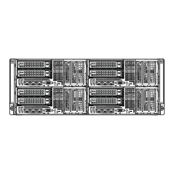
- Page 82 FatTwin F628R3-FT+/FTPT+ User's Manual Figure 6-1. Front and Rear Chassis Views Hot-Swap SATA Drives (8) Control Panel Control Panel IPMI LAN Port Ethernet Ports USB Ports VGA Port Power Supply Chassis Fan Control Panel The control panel for each node is located on the front of the chassis. The LEDs inform you of system status.
- Page 83 Chapter 6: Advanced Chassis Setup Removing the Power Cord Before performing any setup or maintenance on the chassis, use the following procedure to ensure that power has been removed disconnected from the system. Removing the Power Cord 1. Use the operating system to power down the system, following the on-screen prompts.
- Page 84 Hot-swappable hard drives can be removed from the chassis without powering down the server or removing the node from the chassis. Only enterprise level hard drives are recommended for use in Supermicro chassis. F424AL Node Locations in the Chassis Node 2 Node 4 Controls two 3.5"...
- Page 85 Chapter 6: Advanced Chassis Setup Removing Hard Drives from the Front of the Node Removing Hard Drive Carriers from the Chassis 1. Press the release button on the drive carrier. This extends the drive bay handle. 2. Use the handle to pull the drive carrier out of the chassis. Figure 6-3: Removing a Hard Drive Carrier from the Front of the Node...
- Page 86 FatTwin F628R3-FT+/FTPT+ User's Manual Installing Hard Drives into the Drive Carriers The hard drives are mounted in drive carriers to simplify their installation and removal from the chassis. These carriers also help promote proper airfl ow through the drive bays. Removing the Dummy Drive from the Drive Carrier 1.
- Page 87 SAS or SATA Hard Drive Drive Carrier Caution: Enterprise level hard disk drives are recommended for use in Supermicro chassis and servers. For information on recommended HDDs, visit the Supermicro Web site at http://www.supermicro.com/products/nfo/fi les/ storage/SAS-CompList.pdf Note: Refer to the following FTP site for RAID setup guidelines: <ftp://ftp.supermicro.
- Page 88 FatTwin F628R3-FT+/FTPT+ User's Manual Node Confi gurations Node confi guration specifi cations are shown in the table below. F424AL-R1K28BP Front of Node Rear of Node Two low-profi le expansion PCI-E slots and None two (2) 3.5" HDDs Figure 6-6: F424AL Node Rear of the Node Front of...
- Page 89 Chapter 6: Advanced Chassis Setup Removing the Node Cover Each node has a removable cover which will permit access to the nodes components. Removing the Node Cover 1. Power down the system and remove the power cord from the rear of the power supply as described in Section 6-3.
- Page 90 FatTwin F628R3-FT+/FTPT+ User's Manual Removing and Installing the Backplane The F424AL chassis backplane is located behind the hard drives and in front of the serverboard in each serverboard node. Although backplane failure rarely occurs, in the event of a backplane failure, follow the instructions below. Removing the Backplane Removing the Backplane from the Chassis 1.
- Page 91 Chapter 6: Advanced Chassis Setup Installing the Backplane Installing the Backplane into the Chassis 1. Ensure that all of the hard drive carriers have been removed from the bays in the front of the node (see 6-5 Installing and Removing Hard Drives). 1.
- Page 92 Installing the Serverboard Compatible Motherboards For the most up-to-date information on compatible motherboards and other parts, visit the Supermicro Web site at www.supermicro.com. Permanent and Optional Standoffs Standoffs prevent short circuits by creating space between the serverboard and the fl oor of the node. The F424AL chassis includes permanent standoffs in locations used by most motherboards.
- Page 93 Chapter 6: Advanced Chassis Setup 7. Connect the cables between the serverboard, backplane, chassis, front panel, and power supply, as needed. 8. Replace the expansion card bracket and secure the bracket with a screw. 9. Repeat steps 3 - 5 for the remaining nodes. Figure 6-10: Installing the Serverboard in the Serverboard Node Tray 6-13...
- Page 94 FatTwin F628R3-FT+/FTPT+ User's Manual 6-10 Installing Front and Rear Expansion Cards PCI-E Slot Setup The nodes of some F424AL chassis models support expansion cards. To install low-profi le expansion cards, follow the instructions on the following pages. Figure 6-11: PCI-E Slot Shield Confi guration PCI-E Slot Cover 6-14...
- Page 95 Chapter 6: Advanced Chassis Setup F424AL PCI-E Slot Confi gurations Some F424AL chassis models support one or more expansion cards in the PCI-E slots of each node, Refer to the tables below to determine the PCI-E slot confi guration for your particular chassis. F424AL-R1K28BP Front of Node Rear of Node...
- Page 96 FatTwin F628R3-FT+/FTPT+ User's Manual 4. Place and fi rmly set the low--profi le expansion card into the slot. 5. Secure the expansion card using the screw from the slot cover that you previously set aside. 6-11 Installing the Air Shroud Air Shrouds Air shrouds concentrate airfl...
- Page 97 Chapter 6: Advanced Chassis Setup 6-12 Checking the Airfl ow Checking Airfl ow 1. Make sure there are no objects to obstruct airfl ow in and out of the server. In addition, if you are using a front bezel, make sure the bezel's fi lter is replaced periodically.
- Page 98 FatTwin F628R3-FT+/FTPT+ User's Manual 6-13 Replacing System Fans System fans provide cooling for the system and circulate air through the node as a means of lowering the internal temperature. The F424AL system fans are easily removed from the fan tray. There is no need to uninstall any other parts when replacing fans, and only a Phillips screwdriver is required for installation.
- Page 99 Replacement units can be ordered directly from Supermicro (See the contact information in the Preface of this manual). Changing the Power Supply 1.
- Page 100 FatTwin F628R3-FT+/FTPT+ User's Manual 6-15 Power Adapter Board Replacement In the unlikely event of a power adapter board failure, replacement is simple and requires only a Phillips head screwdriver. Changing the Power Adapter Board 1. Power down the system and remove the power cord from the rear of the power supply as described in Section 6-3.
- Page 101 AMI BIOS Setup utility. This Setup utility can be accessed by pressing <Delete> at the appropriate time during system boot. Note: For AMI UEFI BIOS Recovery, please refer to the UEFI BIOS Recovery User Guide posted at http://www.supermicro.com/support/manuals/.
- Page 102 FatTwin F628R3-FT+/FTPT+ User's Manual Starting the Setup Utility Normally, the only visible Power-On Self-Test (POST) routine is the memory test. As the memory is being tested, press the <Delete> key to enter the main menu of the AMI BIOS Setup utility. From the main menu, you can access the other setup screens.
- Page 103 Note: The time is in the 24-hour format. For example, 5:30 P.M. appears as 17:30:00. Supermicro X10DRFF-iG/iTG Version: This item displays the version of the BIOS ROM used in the system. Build Date: This item displays the date when the version of the BIOS ROM used in the system was built.
- Page 104 FatTwin F628R3-FT+/FTPT+ User's Manual Boot Feature Quiet Boot Use this feature to select the screen display between POST messages or the OEM logo at bootup. Select Disabled to display the POST messages. Select Enabled to display the OEM logo instead of the normal POST messages. The options are Enabled and Disabled.
- Page 105 Chapter 7: BIOS Power Confi guration Watch Dog Function Select Enabled to allow the Watch Dog timer to reboot the system when it is inactive for more than 5 minutes. The options are Enabled and Disabled. Power Button Function This feature controls how the system shuts down when the power button is pressed. Select 4 Seconds Override for the user to power off the system after pressing and holding the power button for 4 seconds or longer.
- Page 106 FatTwin F628R3-FT+/FTPT+ User's Manual Clock Spread Spectrum Select Enabled to allow the BIOS to monitor and attempt to reduce the level of Electromagnetic Interference caused by the components whenever needed. The options are Disabled and Enabled. Hyper-Threading (All) Select Enable to support Intel's Hyper-threading Technology to enhance CPU performance.
- Page 107 Chapter 7: BIOS DCU (Data Cache Unit) Streamer Prefetcher (Available when supported by the CPU) If set to Enable, the DCU Streamer prefetcher will prefetch data streams from the cache memory to the DCU (Data Cache Unit) to speed up data accessing and processing to enhance CPU performance.
- Page 108 FatTwin F628R3-FT+/FTPT+ User's Manual Advanced Power Management Confi guration Advanced Power Management Confi guration Power Technology Select Energy Effi cient to support power-saving mode. Select Custom to customize system power settings. Select Disabled to disable power-saving settings. The options are Disable, Energy Effi cient, and Custom. CPU P State Control (Available when Power Technology is set to Custom) EIST (P-States)
- Page 109 Chapter 7: BIOS CPU C3 Report Select Enable to allow the BIOS to report the CPU C3 State (ACPI C2) to the operating system. During the CPU C3 State, the CPU clock generator is turned off. The options are Enable and Disable. CPU C6 Report (Available when Power Technology is set to Custom) Select Enable to allow the BIOS to report the CPU C6 state (ACPI C3) to the operating system.
- Page 110 FatTwin F628R3-FT+/FTPT+ User's Manual Long Dur (Duration) Time Window Use this item to set the time window value (in seconds) over which the TDP (Thermal Design Point) should be maintained. The default setting is 1, which will allow the value to be automatically programed by the system. Pkg (Package) Clmp (Clamping) Limit1 Use this item to set the limit on power performance states for the runtime processor, with P0 being the state with the highest frequency (clock speed)
- Page 111 Chapter 7: BIOS DRAM RAPL (Running Average Power Limit) Extended Range Select Enable to extend the RAPL range for the DRAM modules. The options are Disable and Enable. Chipset Confi guration Warning! Please set the correct settings for the items below. A wrong confi guration setting may cause the system to become malfunction.
- Page 112 FatTwin F628R3-FT+/FTPT+ User's Manual Socket 0 PCIeD00F0 - Port 0/DMI Link Speed This item confi gures the link speed of a PCI-E port specifi ed by the user. The options are Gen 1 (Generation 1) (2.5 GT/s), Gen 2 (Generation 2) (5 GT/s), and Auto.
- Page 113 Chapter 7: BIOS Socket 0 PCIeD01F0 - Port 1A/Socket 0 PCIeD02F0 - Port 2A/ Socket 0 PCIeD20F2 - Port 2C/Socket 0 PCIeD03F0 - Port 3A/Socket 0 PCIeD03F2 - Port 3C PCI-E Port Select Enable to enable the PCI-E port specifi ed by the user. The options are Auto, Enable, and Disable.
- Page 114 FatTwin F628R3-FT+/FTPT+ User's Manual Fatal Err (Error) Over Select Enable to force fatal error prorogation to the IIO core error logic for the port specifi ed by the user. The options are Disable and Enable. Non-Fatal Err (Error) Over Select Enable to force non-fatal error prorogation to the IIO core error logic for the port specifi...
- Page 115 Chapter 7: BIOS Gen3 (Generation 3) DN RX Preset Hint Use this item to set the Preset Hint mode for PCI-E Gen3 downstream receiving (RX) from the master device to a slave device. The options are Auto, P0 (-6.0 dB), P1 (-7.0 dB), P2 (-8.0 dB), P3 (-9.0 dB), P4 (-10.0 dB) P5 (-11.0 dB), and P6 (-12.0 dB).
- Page 116 FatTwin F628R3-FT+/FTPT+ User's Manual No PCIe Port Active ECO (Engineer Change Order) This feature provides a work-around solution when there is no active PCI device detected by the BIOS. The options are PCU Squelch Exit Ignore Option and Reset the SQ FLOP by CSR Option.. Socket 1 PCIeD00F0 - Port 0/DMI/Socket 1 PCIeD01F0 - Port 1A/ Socket 1 PCIeD02F0 - Port 2A/Socket 1 PCIeD20F2 - Port 2C/Socket 1 PCIeD03F0 - Port 3A...
- Page 117 Chapter 7: BIOS PCI-E Port L1 Exit Latency Use this item to set the length of time required for the port specifi ed by the user to complete the transition from L1 to L0. The default setting is <1uS, 1uS - 2uS, 2uS - 4uS, 4uS - 8uS, 8uS - 16uS, 16uS - 32uS, 32uS - 64uS, and >64uS.
- Page 118 FatTwin F628R3-FT+/FTPT+ User's Manual Gen3 (Generation 3) DN TX Preset Use this item to set the Preset mode for PCI-E Gen3 downstream transmitting (TX) from the master device to a slave device. The options are Auto, P0 (-6.0/0.0 dB), P1 (-3.5/0.0 dB), P2 (-4.5/0.0 dB), P3 (-2.5/0.0 dB), P4 (0.0/0.0 dB), P5 (0.0/2.0 dB), P6 (0.0/2.5 dB), P7 (-6.0 /3.5 dB), P8 (-3.5/3.5 dB), and P9 (0.0/3.5 dB).
- Page 119 Chapter 7: BIOS Relaxed Ordering Select Enable to enable Relaxed Ordering support which will allow certain transactions to violate the strict-ordering rules of PCI bus for a transaction to be completed prior to other transactions that have already been enquired. The options are Disable and Enable. Intel VT for Directed I/O (VT-d) ®...
- Page 120 FatTwin F628R3-FT+/FTPT+ User's Manual Link Frequency Select Use this item to select the desired frequency for QPI Link connections. The options are 6.4GB/s, 8.0GB/s, 9.6GB/s, Auto, and Auto Limited. Link L0p Enable Select Enable for Link L0p support to reduce power consumption. The options are Enable and Disable.
- Page 121 Chapter 7: BIOS Data Scrambling Select Enabled to enable data scrambling to enhance system performance and data integrity. The options are Auto, Disabled and Enabled. DRAM RAPL (Running Average Power Limit) Baseline Use this feature to set the run-time power-limit baseline for DRAM modules. The options are Disable, DRAM RAPL Mode 0, and DRAM RAPL Mode 1.
- Page 122 FatTwin F628R3-FT+/FTPT+ User's Manual Memory Rank Sparing Select Enable to enable memory-sparing support for memory ranks to improve memory performance. The options are Disabled and Enabled. Patrol Scrub Patrol Scrubbing is a process that allows the CPU to correct correctable memory errors detected on a memory module and send the correction to the requestor (the original source).
- Page 123 Chapter 7: BIOS South Bridge Confi guration The following South Bridge information will display: USB Confi guration • USB Module Version • USB Devices Legacy USB Support Select Enabled to support onboard legacy USB devices. Select Auto to disable legacy support if there are no legacy USB devices present. Select Disabled to have all USB devices available for EFI applications only.
- Page 124 FatTwin F628R3-FT+/FTPT+ User's Manual EHCI2 Select Enabled to enable EHCI (Enhanced Host Controller Interface) support on USB 2.0 connector #2 (-at least one USB 2.0 connector should be enabled for EHCI support.) The options are Disabled and Enabled. SATA Confi guration When this submenu is selected, AMI BIOS automatically detects the presence of the SATA devices that are supported by the Intel PCH chip and displays the following items:...
- Page 125 Chapter 7: BIOS Spin Up Device On an edge detect from 0 to 1, set this item to allow the PCH to initialize the device. The options are Enabled and Disabled. SATA Device Type Use this item to specify if the SATA port specifi ed by the user should be connected to a Solid State drive or a Hard Disk Drive.
- Page 126 FatTwin F628R3-FT+/FTPT+ User's Manual Serial ATA Port 0~ Port 5 This item displays the information of a SATA device installed on the SATA port specifi ed by the user. • Model number of drive and capacity • Software Preserve Port 0~ Port 5 Select Enabled to enable a SATA port specifi...
- Page 127 Chapter 7: BIOS Support Aggressive Link Power Management When this item is set to Enabled, the SATA AHCI controller manages the power usage of the SATA link. The controller will put the link to a low power state when the I/O is inactive for an extended period of time, and the power state will return to normal when the I/O becomes active.
- Page 128 FatTwin F628R3-FT+/FTPT+ User's Manual Support Aggressive Link Power Management When this item is set to Enabled, the SATA AHCI controller manages the power usage of the sSATA link. The controller will put the link to a low power state when the I/O is inactive for an extended period of time, and the power state will return to normal when the I/O becomes active.
- Page 129 Chapter 7: BIOS Server ME (Management Engine) Confi guration This feature displays the following system ME confi guration settings. • General ME Confi guration • Operational Firmware Version • Recovery Firmware Version • ME Firmware Features • ME Firmware Status #1 •...
- Page 130 FatTwin F628R3-FT+/FTPT+ User's Manual PCIe/PCI/PnP Confi guration PCI Latency Timer Use this item to confi gure the PCI latency timer for a device installed on a PCI bus. Select 32 to set the PCI latency timer to 32 PCI clock cycles. The options are 32, 64, 96, 128, 160, 192, 224, and 248 (PCI Bus Clocks).
- Page 131 Chapter 7: BIOS Warning: Enabling ASPM support may cause some PCI-E devices to fail! MMIOHBase Use this item to select the I/O base memory size according to memory-address mapping for the PCH chip. The base memory size must be between 4032G to 4078G.
- Page 132 FatTwin F628R3-FT+/FTPT+ User's Manual Super IO Confi guration Super IO Chip AST2400 Serial Port 1 Confi guration/Serial Port 2 Confi guration Serial Port 1/Serial Port 2 Select Enabled to enable the onboard serial port specifi ed by the user. The options are Enabled and Disabled.
- Page 133 Chapter 7: BIOS Serial Port Console Redirection COM 1 COM 1 Console Redirection Select Enabled to enable COM Port 1 Console Redirection, which will allow a client machine to be connected to a host machine at a remote site for networking. The options are Disabled and Enabled.
- Page 134 FatTwin F628R3-FT+/FTPT+ User's Manual Stop Bits A stop bit indicates the end of a serial data packet. Select 1 Stop Bit for standard serial data communication. Select 2 Stop Bits if slower devices are used. The options are 1 and 2. Flow Control Use this item to set the fl...
- Page 135 Chapter 7: BIOS SOL/COM2 SOL/COM2 Console Redirection Select Enabled to use the SOL port for Console Redirection. The options are Enabled and Disabled. *If the item above set to Enabled, the following items will become available for user's confi guration: SOL/COM2 Console Redirection Settings Use this feature to specify how the host computer will exchange data with the client computer, which is the remote computer used by the user.
- Page 136 FatTwin F628R3-FT+/FTPT+ User's Manual Stop Bits A stop bit indicates the end of a serial data packet. Select 1 Stop Bit for standard serial data communication. Select 2 Stop Bits if slower devices are used. The options are 1 and 2. Flow Control Use this feature to set the fl...
- Page 137 Chapter 7: BIOS Legacy Console Redirection Settings Use this feature to specify how the host computer will communicate with the client compute at a remote site via legacy devices. Legacy Serial Redirection Port The feature selects a legacy serial port to be used for Console Redirection. The options are COM1 Console Redirection and COM2/SOL Console Redirection.
- Page 138 FatTwin F628R3-FT+/FTPT+ User's Manual Bits Per Second This item sets the transmission speed for a serial port used in Console Redirection. Make sure that the same speed is used in both host computer and the client computer. A lower transmission speed may be required for long and busy lines.
- Page 139 Chapter 7: BIOS Intel TXT (LT-SX) Confi guration This submenu allows the user to confi gure the following TXT settings. TXT Support Select Enabled to enable Intel Trusted Execution Technology (TXT) support. The options are Disabled and Enabled. Note: If the option for this item (TXT Support) is set to Enabled, be sure to disable EV DFX (Device Function On-Hide) support for the system to work properly.
- Page 140 FatTwin F628R3-FT+/FTPT+ User's Manual iSCSI Confi guration This item displays iSCSI confi guration information: iSCSI Initiator Name Use this item to enter the name of the iSCSI Initiator, which is a unique name used in the world. The name must in the IQN format. The following submenu will be available for confi...
- Page 141 Chapter 7: BIOS Event Logs This submenu allows the user to confi gure Event Log settings. Change SMBIOS Event Log Settings This feature allows the user to confi gure SMBIOS Event settings. Enabling/Disabling Options SMBIOS Event Log Select Enabled to enable SMBIOS (System Management BIOS) Event Logging during system boot.
- Page 142 FatTwin F628R3-FT+/FTPT+ User's Manual Memory Correctable Error Threshold (Available when the item above- Runtime Error Logging Support is set to Enabled) Use this item to specify the threshold value for correctable memory-error logging, which sets a limit on the maximum number of events that can be logged in the memory-error log at a given time.
- Page 143 Chapter 7: BIOS IPMI This submenu allows the user to confi gure Intelligent Platform Management Interface (IPMI) settings. BMC (Baseboard Management Controller) Firmware Revision This item indicates the BMC fi rmware revision used in your system. Status of BMC This item indicates the status of the onboard BMC chip installed in your system. ...
- Page 144 FatTwin F628R3-FT+/FTPT+ User's Manual When SEL is Full This feature allows the user to determine what the AMI BIOS should do when the system event log is full. Select Erase Immediately to erase all events in the log when the system event log is full. The options are Do Nothing and Erase Immediately. Note: After making changes on a setting, be sure to reboot the system for the changes to take effect.
- Page 145 Chapter 7: BIOS Security Settings This submenu allows the user to confi gure the following security settings for the system. Administrator Password Use this feature to set the administrator password which is required before entering the BIOS setup utility. The length of the password should be from 3 characters to 20 characters long.
- Page 146 FatTwin F628R3-FT+/FTPT+ User's Manual Boot Settings This submenu allows the user to confi gure Boot settings for this system: Boot Confi guration Boot Mode Select Use this item to select the type of device to be used for system boot. The options are Legacy, UEFI, and Dual.
- Page 147 Chapter 7: BIOS Delete Boot Option Use this item to select a boot device to delete from the boot priority list. Delete Boot Option Select the target boot device to delete from the boot priority list. Delete Driver Option Use this item to select a driver to delete from the boot priority list.
- Page 148 FatTwin F628R3-FT+/FTPT+ User's Manual Save & Exit This submenu allows the user to confi gure the following Save & Exit settings: Discard Changes and Exit Select this item to exit from the BIOS setup without making any permanent changes to the system confi guration, and reboot the computer. Save Changes and Reset When you have completed the system confi...
- Page 149 Chapter 7: BIOS Restore Defaults Select this item and press <Enter> to load the manufacture default settings which are designed for maximum system performance but not for maximum stability. Save As User Defaults Select this item and press <Enter> to save the current BIOS settings as user's default settings for future use.
- Page 150 FatTwin F628R3-FT+/FTPT+ User's Manual Notes 7-50...
- Page 151 Appendix A: BIOS Error Beep Codes Appendix A BIOS Error Beep Codes During the POST (Power-On Self-Test) routines, which are performed each time the system is powered on, errors may occur. Non-fatal errors are those which, in most cases, allow the system to continue the boot-up process.
- Page 152 FatTwin F628R3-FT+/FTPT+ User's Manual Notes...
- Page 153 2400/2133/1866/1600 MHz speeds and up to 4 GB, 8 GB, 16 GB, 32 GB, 64 GB or 128 GB (3DS LRDIMM only) size at 1.2V voltage. Note: refer to Section 5-5 for details on installation. Note: Check the Supermicro website (www.supermicro.com) for the latest memory support information. SAS/SATA Drive Bays Each of the FatTwin F628R3-FT+/FTPT+ nodes contains two (2) hot-swap drive trays for 3.5"...
- Page 154 FatTwin F628R3-FT+/FTPT+ User's Manual Chassis F424AL-R1K28BP (4U rackmount) Dimensions: (WxHxD) 17.63 x 6.96 x 29 in. (448 x 177 x 737 mm) Weight Gross (Bare Bone): 150 lbs (68.04 kg) System Cooling The system has eight (8) 8-cm PWM system cooling fans in the chassis System Input Requirements AC Input Voltage: 100-140V (1000W), 180-240V (1280W) AC auto-range Rated Input Current: 12 - 8A (1000W), 8 - 6A (1280W)
- Page 155 Appendix B: System Specifi cations Regulatory Compliance Electromagnetic Emissions: FCC Class A, EN 55022 Class A, EN 61000-3-2/-3- 3, CISPR 22 Class A Electromagnetic Immunity: EN 55024/CISPR 24, (EN 61000-4-2, EN 61000-4-3, EN 61000-4-4, EN 61000-4-5, EN 61000-4-6, EN 61000-4-8, EN 61000-4-11) Safety: CSA/EN/IEC/UL 60950-1 Compliant, UL or CSA Listed (USA and Canada), CE Marking (Europe) California Best Management Practices Regulations for Perchlorate Materials:...
- Page 156 FatTwin F628R3-FT+/FTPT+ User's Manual (continued from front) The products sold by Supermicro are not intended for and will not be used in life support systems, medical equipment, nuclear facilities or systems, aircraft, aircraft devices, aircraft/emergency communication devices or other critical systems whose failure to perform be reasonably expected to result in signifi...
Need help?
Do you have a question about the FatTwin F628R3-FT+ and is the answer not in the manual?
Questions and answers