
Related Manuals for Supermicro FatTwin F627G2-FT+


Summary of Contents for Supermicro FatTwin F627G2-FT+
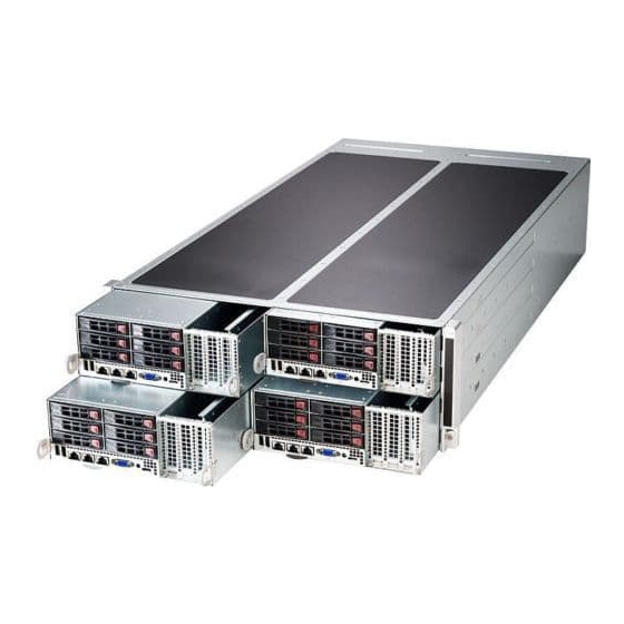
- Page 1 UPER ® FatTwin F627G2-FT+ F627G2-FTPT+ F627G2-F73+ F627G2-F73PT+ USER'S MANUAL Revision 1.0b...
- Page 2 This product, including software and documentation, is the property of Supermicro and/or its licensors, and is supplied only under a license. Any use or reproduction of this product is not allowed, except as expressly permitted by the terms of said license.
- Page 3 Preface Preface About This Manual This manual is written for professional system integrators and PC technicians. It provides information for the installation and use of the FatTwin™ F627G2-FT+/FTPT+/F73+/F73PT+. Installation and maintainance should be performed by experienced technicians only. The FatTwin F627G2-FT+/FTPT+/F73+/F73PT+ is a high-end server based on the F424BG-R1K62B 4U rackmount chassis and a dual processor X9DRFF-iG+/iTG+/7G+/7TG+ serverboard.
- Page 4 FatTwin F627G2-FT+/FTPT+/F73+/F73PT+ USER'S MANUAL Chapter 5: Advanced Serverboard Setup Chapter 5 provides detailed information on the X9DRFF-iG+/iTG+/7G+/7TG+ serverboards, including the locations and functions of connections, headers and jumpers. Refer to this chapter when adding or removing processors or main memory and when reconfi...
- Page 5 FatTwin F627G2-FT+/FTPT+/F73+/F73PT+ USER'S MANUAL Notes...
-
Page 6: Table Of Contents
Mounting Rails ....................1-6 Advanced Power Management ............... 1-6 Intel® Intelligent Power Node Manager (NM) ..........1-6 Manageability Engine (ME) ................1-6 Contacting Supermicro ..................1-8 Fat Twin: System Notes .................. 1-9 Nodes ......................1-9 System Power ....................1-9 SAS/SATA Backplane/Drives ................1-9 Chapter 2 Server Installation Overview ...................... - Page 7 Table of Contents Choosing a Setup Location ................2-2 Rack Precautions .................... 2-2 Server Precautions ..................2-2 Rack Mounting Considerations ............... 2-3 Ambient Operating Temperature ..............2-3 Reduced Airfl ow ..................2-3 Mechanical Loading ................... 2-3 Circuit Overloading ..................2-3 Reliable Ground ..................
- Page 8 FatTwin F627G2-FT+/FTPT+/F73+/F73PT+ USER'S MANUAL Chapter 5 Advanced Motherboard Setup Handling the Motherboard ................5-1 Precautions ..................... 5-1 Unpacking ....................... 5-1 Connecting Cables ..................5-2 Connecting Power Cables ................5-2 Connecting Data Cables ................. 5-2 Control Panel Connectors and I/O Ports ............5-3 Processor and Heatsink Installation..............
- Page 9 Table of Contents Power Distributor Board Replacement ............6-12 6-10 Installing the Motherboard ................6-14 Compatible Motherboards ................6-14 Permanent and Optional Standoffs ............... 6-14 6-11 Installing Front and Rear Expansion Cards ..........6-16 PCIE Slot Setup .................... 6-16 F424BG PCIE Slot Confi gurations ..............6-16 Installing a Low-Profi...
- Page 10 FatTwin F627G2-FT+/FTPT+/F73+/F73PT+ USER'S MANUAL Notes...
-
Page 11: Chapter 1 Introduction
X9DRFF-iG+/iTG+/7G+/7TG+ dual processor serverboard in four hot-swap nodes. Please refer to our web site for information on operating systems that have been certifi ed for use with the system (www.supermicro.com). In addition to the serverboard and chassis, various hardware components have... -
Page 12: Serverboard Features
The X9DRFF-iG+/iTG+/7G+/7TG+ supports single or dual Intel® E5-2600 series processors in Socket R LGA 2011 sockets. Please refer to the serverboard description pages on our web site for a complete listing of supported processors (www.supermicro.com). Memory The X9DRFF-iG+/iTG+/7G+/7TG+ has sixteen (16) memory sockets that... -
Page 13: Pci Expansion Slots
X9DRFF-iTG+/X9DRFF-7TG+ serverboard's feature two 10 Gb Ethernet ports instead) and one dedicated IPMI LAN port. Note: For IPMI Confi guration Instructions, please refer to the Embedded IPMI Configuration User's Guide available @ http://www.supermicro.com/support/ manuals/. Graphics Controller The X9DRFF-iG+/iTG+/7G+/7TG+ features an integrated Matrox G200ew, 16 MB DDR2 graphics controller. -
Page 14: Wpcm450R Pci System Interface
• RMCP+ protocol supported Note: For more information on IPMI confi guration, please refer to the IPMI User's Guide posted on our website at http://www.supermicro.com/support/manuals/. Power Supply Please connect the power cable from the SMC-Proprietary Adaptor (BPN-ADP- F418L) to the motherboard in order to provide power to the system. -
Page 15: Server Chassis Features
The air shroud will differ for different motherboards. If using a motherboard which is not the default in the chassis, refer to the optional parts in the Appendix of this manual, or the Supermicro Web site at www.supermicro.com... -
Page 16: Mounting Rails
FatTwin F627G2-FT+/FTPT+/F73+/F73PT+ USER'S MANUAL Mounting Rails The F424BG includes a set of rails, and can be placed in a rack for secure storage and use. To setup your rack, follow the step-by-step instructions included in this manual. Advanced Power Management Intel®... - Page 17 Chapter 1: Introduction Figure 1-1. Intel C602 Chipset: System Block Diagram Note: This is a general block diagram and may not exactly repre- sent the features on your motherboard. See the previous pages for the actual specifi cations of your motherboard. This block diagram is intended for your reference only.
-
Page 18: Contacting Supermicro
Super Micro Computer, Inc. 980 Rock Ave. San Jose, CA 95131 U.S.A. Tel: +1 (408) 503-8000 Fax: +1 (408) 503-8008 Email: marketing@supermicro.com (General Information) support@supermicro.com (Technical Support) Web Site: www.supermicro.com Europe Address: Super Micro Computer B.V. Het Sterrenbeeld 28, 5215 ML... -
Page 19: Fat Twin: System Notes
Chapter 1: Introduction Fat Twin: System Notes As a FatTwin confi guration, the FatTwin F627G2-FT+/FTPT+/F73+/F73PT+ is a unique server system. With four system boards incorporated into a single chassis acting as four separate nodes, there are several points you should keep in mind. Nodes Each of the four serverboards act as a separate node in the system. - Page 20 FatTwin F627G2-FT+/FTPT+/F73+/F73PT+ USER'S MANUAL Notes 1-10...
-
Page 21: Chapter 2 Server Installation
Chapter 2: Server Installation Chapter 2 Server Installation Overview This chapter provides a quick setup checklist to get your FatTwin F627G2-FT+/FTPT+/F73+/F73PT+ up and running. Following these steps in the order given should enable you to have the system operational within a minimum amount of time. -
Page 22: Warnings And Precautions
FatTwin F627G2-FT+/FTPT+/F73+/F73PT+ USER'S MANUAL Warnings and Precautions Choosing a Setup Location • Leave enough clearance in front of the rack to enable you to open the front door completely (~25 inches) and approximately 30 inches of clearance in the back of the rack to allow for suffi... -
Page 23: Rack Mounting Considerations
Chapter 2: Server Installation Rack Mounting Considerations Warning! To prevent bodily injury when mounting or servicing this unit in a rack, you must take special precautions to ensure that the system remains stable. The following guidelines are provided to ensure your safety: •... -
Page 24: Reliable Ground
FatTwin F627G2-FT+/FTPT+/F73+/F73PT+ USER'S MANUAL Reliable Ground A reliable ground must be maintained at all times. To ensure this, the rack itself should be grounded. Particular attention should be given to power supply connections other than the direct connections to the branch circuit (i.e. the use of power strips, etc.). -
Page 25: Locking Tabs
Chapter 2: Server Installation Locking Tabs Each inner rail has a locking tab. This tab locks the chassis into place when installed and pushed fully into the rack. These tabs also lock the chassis in place when fully extended from the rack. This prevents the server from coming completely out of the rack when when the chassis is pulled out for servicing. -
Page 26: Installing The Rails On A Rack
FatTwin F627G2-FT+/FTPT+/F73+/F73PT+ USER'S MANUAL Installing the Rails on a Rack Installing the Rails 1. Adjust the length of both rails as described on the previous page. 2. Align the front section of the outer rail with the slots on the front post of the rack. -
Page 27: Chassis Installation
Chapter 2: Server Installation Chassis Installation Installing the Chassis into a Rack 1. Confi rm that the rails are correctly installed on the rack. 2. Align the bottom of the chassis with the bottom of the rails. 3. Insert the chassis into the rails, keeping the pressure even on both sides, pushing the chassis into the rack until it clicks into the locked position. -
Page 28: Checking The Serverboard Setup
FatTwin F627G2-FT+/FTPT+/F73+/F73PT+ USER'S MANUAL Checking the Serverboard Setup After you install the FatTwin F627G2-FT+/FTPT+/F73+/F73PT+ in the rack, you will need to open the unit to make sure the serverboard is properly installed and all the connections have been made. Accessing the inside of the System Before operating the server for the fi... -
Page 29: Checking The Drive Bay Setup
Chapter 2: Server Installation Checking the Drive Bay Setup Next, you should check to make sure the peripheral drives and the SATA drives have been properly installed and all connections have been made. Checking the Drives 1. All drives are accessable from the front of the server. A hard drive can be installed and removed from the front of the chassis without removing the top chassis cover. - Page 30 FatTwin F627G2-FT+/FTPT+/F73+/F73PT+ USER'S MANUAL Notes 2-10...
-
Page 31: Chapter 3 System Interface
Chapter 3: System Interface Chapter 3 System Interface Overview There are several buttons and LEDs are located on each of the motherboard nodes and on the drive carriers to keep you constantly informed of the overall status of the system. This chapter explains the meanings of all LED indicators and the appropriate re- sponse you may need to take. -
Page 32: Control Panel Buttons
FatTwin F627G2-FT+/FTPT+/F73+/F73PT+ USER'S MANUAL Control Panel Buttons • Power: The main power button on each of the four control panels is used to apply or remove power from the power supply to each of the four systems in the chassis. Turning off system power with this button removes the main power, but keeps standby power supplied to the system. -
Page 33: Drive Carrier Leds
Chapter 3: System Interface Drive Carrier LEDs The F424BG chassis supports hot-swappable 2.5" SAS/SATA drives include the following LED indicators. SAS/SATA Drives Each SAS/SATA drive carrier has two LEDs. • Blue: Each Serial ATA drive carrier has a blue LED. When illuminated, this blue LED (on the front of the SATA drive carrier) indicates drive activity. - Page 34 FatTwin F627G2-FT+/FTPT+/F73+/F73PT+ USER'S MANUAL Notes...
-
Page 35: Chapter 4 Standardized Warning Statements For Ac Systems
Only certifi ed technicians should attempt to install or confi gure components. Read this appendix in its entirety before installing or confi guring components in the Supermicro chassis. These warnings may also be found on our web site at http://www.supermicro.com/ about/policies/safety_information.cfm. Warning Defi nition Warning! This warning symbol means danger. - Page 36 FatTwin F627G2-FT+/FTPT+/F73+/F73PT+ USER'S MANUAL Warnung WICHTIGE SICHERHEITSHINWEISE Dieses Warnsymbol bedeutet Gefahr. Sie befi nden sich in einer Situation, die zu Verletzungen führen kann. Machen Sie sich vor der Arbeit mit Geräten mit den Gefahren elektrischer Schaltungen und den üblichen Verfahren zur Vorbeugung vor Unfällen vertraut.
- Page 37 Warning Statements for AC Systems ﺟﺴﺪﻳﺔ ﺍﺻﺎﺑﺔ ﺗﺘﺴﺒﺐ ﻓﻲ ﺣﺎﻟﺔ ﻳﻤﻜﻦ ﺃﻥ ﺍﻧﻚ ﻓﻲ ﺧﻄﺮ ﻳﻌﻨﻲ ﻫﺬﺍ ﺍﻟﺮﻣﺰ !ﺗﺤﺬﻳﺮ ﺍﻟﺪﻭﺍﺋﺮ ﺑﺎﻟﻤﺨﺎﻁﺮ ﺍﻟﻨﺎﺟﻤﺔ ﻋﻦ ﻦ ﻋﻠﻰ ﻋﻠﻢ ، ﻛ ﻣﻌﺪﺍﺕ ﺗﻌﻤﻞ ﻋﻠﻰ ﺃﻱ ﻗﺒﻞ ﺃﻥ ﺍﻟﻜﻬﺮﺑﺎﺋﻴﺔ ﺣﻮﺍﺩﺙ ﺃﻱ ﻭﻗﻮﻉ ﻤﻨﻊ ﻟ ﺍﻟﻮﻗﺎﺋﻴﺔ...
-
Page 38: Installation Instructions
FatTwin F627G2-FT+/FTPT+/F73+/F73PT+ USER'S MANUAL Installation Instructions Warning! Read the installation instructions before connecting the system to the power source. 設置手順書 システムを電源に接続する前に、 設置手順書をお読み下さい。 警告 将此系统连接电源前,请先阅读安装说明。 警告 將系統與電源連接前,請先閱讀安裝說明。 Warnung Vor dem Anschließen des Systems an die Stromquelle die Installationsanweisungen lesen. ¡Advertencia! Lea las instrucciones de instalación antes de conectar el sistema a la red de alimentación. -
Page 39: Circuit Breaker
Chapter 4: Warning Statements for AC Systems Circuit Breaker Warning! This product relies on the building's installation for short-circuit (overcurrent) protection. Ensure that the protective device is rated not greater than: 250 V, 20 A. サーキッ ト ・ ブレーカー この製品は、 短絡 (過電流) 保護装置がある建物での設置を前提としています。 保護装置の定格が250 V、... -
Page 40: Power Disconnection Warning
FatTwin F627G2-FT+/FTPT+/F73+/F73PT+ USER'S MANUAL ﻓﻲ ﺍﻟﺘﻲ ﺗﻢ ﺗﺜﺒﻴﺘﻬﺎ ﻣﻦ ﺍﻟﺪﻭﺍﺋﺮﺍﻟﻘﺼﻴﺮﺓ ﺍﻟﺤﻤﺎﻳﺔ ﻣﻌﺪﺍﺕ ﻳﻌﺘﻤﺪ ﻋﻠﻰ ﻫﺬﺍ ﺍﻟﻤﻨﺘﺞ ﺍﻟﻤﺒﻨﻰ ﺃﻛﺜﺮ ﻣﻦ ﻟﻴﺲ ﻮﻗﺎﺋﻲ ﺍﻟ ﺍﻟﺠﻬﺎﺯ ﺗﻘﻴﻴﻢ ﺃﻥ ﺗﺄﻛﺪ ﻣﻦ 20A, 250V 경고! 이 제품은 전원의 단락(과전류)방지에 대해서 전적으로 건물의 관련 설비에 의존합니다. 보호장치의 정격이 반드시 250V(볼트), 20A(암페어)를 초과하지 않도록... - Page 41 Chapter 4: Warning Statements for AC Systems Warnung Das System muss von allen Quellen der Energie und vom Netzanschlusskabel getrennt sein, das von den Spg.Versorgungsteilmodulen entfernt wird, bevor es auf den Chassisinnenraum zurückgreift, um Systemsbestandteile anzubringen oder zu entfernen. ¡Advertencia! El sistema debe ser disconnected de todas las fuentes de energía y del cable eléctrico quitado de los módulos de fuente de alimentación antes de tener acceso el interior del chasis para instalar o para quitar componentes de sistema.
-
Page 42: Equipment Installation
FatTwin F627G2-FT+/FTPT+/F73+/F73PT+ USER'S MANUAL Equipment Installation Warning! Only trained and qualifi ed personnel should be allowed to install, replace, or service this equipment. 機器の設置 トレーニングを受け認定された人だけがこの装置の設置、 交換、 またはサービスを許可 されています。 警告 只有经过培训且具有资格的人员才能进行此设备的安装、更换和维修。 警告 只有經過受訓且具資格人員才可安裝、更換與維修此設備。 Warnung Das Installieren, Ersetzen oder Bedienen dieser Ausrüstung sollte nur geschultem, qualifi... -
Page 43: Restricted Area
Chapter 4: Warning Statements for AC Systems Waarschuwing Deze apparatuur mag alleen worden geïnstalleerd, vervangen of hersteld door geschoold en gekwalifi ceerd personeel. Restricted Area Warning! This unit is intended for installation in restricted access areas. A restricted access area can be accessed only through the use of a special tool, lock and key, or other means of security. -
Page 44: Battery Handling
FatTwin F627G2-FT+/FTPT+/F73+/F73PT+ USER'S MANUAL אזור עם גישה מוגבלת !אזהרה יש להתקין את היחידה באזורים שיש בהם הגבלת גישה. הגישה ניתנת בעזרת .('כלי אבטחה בלבד )מפתח, מנעול וכד ﻣﺤﻈﻮﺭﺓ ﻣﻨﺎﻁﻖ ﻟﺘﺮﻛﻴﺒﻬﺎ ﻓﻲ ﻫﺬﻩ ﺍﻟﻮﺣﺪﺓ ﺗﺨﺼﻴﺺ ﺗﻢ ،ﺃﺩﺍﺓ ﺧﺎﺻﺔ ﻣﻦ ﺧﻼﻝ ﺍﺳﺘﺨﺪﺍﻡ ﻓﻘﻂ... - Page 45 Chapter 4: Warning Statements for AC Systems Warnung Bei Einsetzen einer falschen Batterie besteht Explosionsgefahr. Ersetzen Sie die Batterie nur durch den gleichen oder vom Hersteller empfohlenen Batterietyp. Entsorgen Sie die benutzten Batterien nach den Anweisungen des Herstellers. Attention Danger d'explosion si la pile n'est pas remplacée correctement. Ne la remplacer que par une pile de type semblable ou équivalent, recommandée par le fabricant.
-
Page 46: Redundant Power Supplies
FatTwin F627G2-FT+/FTPT+/F73+/F73PT+ USER'S MANUAL Redundant Power Supplies Warning! This unit might have more than one power supply connection. All connections must be removed to de-energize the unit. 冗長電源装置 このユニッ トは複数の電源装置が接続されている場合があります。 ユニッ トの電源を切るためには、 すべての接続を取り外さなければなりません。 警告 此部件连接的电源可能不止一个,必须将所有电源断开才能停止给该部件供电。 警告 此裝置連接的電源可能不只一個,必須切斷所有電源才能停止對該裝置的供電。 Warnung Dieses Gerät kann mehr als eine Stromzufuhr haben. Um sicherzustellen, dass der Einheit kein trom zugeführt wird, müssen alle Verbindungen entfernt werden. -
Page 47: Backplane Voltage
Chapter 4: Warning Statements for AC Systems ﺍﻣﺪﺍﺩ ﺍﻟﻄﺎﻗﺔ ﺑﻮﺣﺪﺍﺕ ﻋﺪﺓ ﺍﺗﺼﺎﻻﺕ ﺠﻬﺎﺯ ﺍﻟ ﻳﻜﻮﻥ ﻟﻬﺬﺍ ﻗﺪ ﺍﻟﻜﻬﺮﺑﺎء ﻋﻦ ﻮﺣﺪﺓ ﺍﻟ ﻟﻌﺰﻝ ﻛﺎﻓﺔ ﺍﻻﺗﺼﺎﻻﺕ ﻳﺠﺐ ﺇﺯﺍﻟﺔ 경고! 이 장치에는 한 개 이상의 전원 공급 단자가 연결되어 있을 수 있습니다. 이 장치에 전원을... -
Page 48: Comply With Local And National Electrical Codes
FatTwin F627G2-FT+/FTPT+/F73+/F73PT+ USER'S MANUAL Attention Lorsque le système est en fonctionnement, des tensions électriques circulent sur le fond de panier. Prendre des précautions lors de la maintenance. מתח בפנל האחורי !הרה אז קיימת סכנת מתח בפנל האחורי בזמן תפעול המערכת. יש להיזהר במהלך .העבודה... -
Page 49: Product Disposal
Chapter 4: Warning Statements for AC Systems ¡Advertencia! La instalacion del equipo debe cumplir con las normas de electricidad locales y nacionales.Attention L'équipement doit être installé conformément aux normes électriques nationales et locales. תיאום חוקי החשמל הארצי !אזהרה הציוד חייבת להיות תואמת לחוקי החשמל המקומיים והארציים התקנת... -
Page 50: Hot Swap Fan Warning
FatTwin F627G2-FT+/FTPT+/F73+/F73PT+ USER'S MANUAL Warnung Die Entsorgung dieses Produkts sollte gemäß allen Bestimmungen und Gesetzen des Landes erfolgen. ¡Advertencia! Al deshacerse por completo de este producto debe seguir todas las leyes y reglamentos nacionales. Attention La mise au rebut ou le recyclage de ce produit sont généralement soumis à des lois et/ou directives de respect de l'environnement. - Page 51 Chapter 4: Warning Statements for AC Systems 当您从机架移除风扇装置,风扇可能仍在转动。小心不要将手指、螺丝起子和其他 物品太靠近风扇 警告 當您從機架移除風扇裝置,風扇可能仍在轉動。小心不要將手指、螺絲起子和其他 物品太靠近風扇。 Warnung Die Lüfter drehen sich u. U. noch, wenn die Lüfterbaugruppe aus dem Chassis genommen wird. Halten Sie Finger, Schraubendreher und andere Gegenstände von den Öffnungen des Lüftergehäuses entfernt. ¡Advertencia! Los ventiladores podran dar vuelta cuando usted quite ell montaje del ventilador del chasis.
-
Page 52: Power Cable And Ac Adapter
fi re. Electrical Appliance and Material Safety Law prohibits the use of UL or CSA -certifi ed cables (that have UL/CSA shown on the code) for any other electrical devices than products designated by Supermicro only. 電源コードとACアダプター... - Page 53 Appareils électroménagers et de loi sur la sécurité Matériel interdit l'utilisation de UL ou CSA câbles certifi és qui ont UL ou CSA indiqué sur le code pour tous les autres appareils électriques que les produits désignés par Supermicro seulement.
- Page 54 Elektrisch apparaat en veiligheidsinformatiebladen wet verbiedt het gebruik van UL of CSA gecertifi ceerde kabels die UL of CSA die op de code voor andere elektrische apparaten dan de producten die door Supermicro alleen.
-
Page 55: Chapter 5 Advanced Motherboard Setup
Chapter 5: Advanced Motherboard Setup Chapter 5 Advanced Motherboard Setup This chapter covers the steps required to install the X9DRFF-iG+/iTG+/7G+/7TG+ motherboard into the chassis, connect the data and power cables and install add-on cards. All motherboard jumpers and connections are also described. A layout and quick reference chart are included in this chapter for your reference. -
Page 56: Connecting Cables
FatTwin F627G2-FT+/FTPT+/F73+/F73PT+ USER'S MANUAL Connecting Cables The FatTwin F627G2-FT+/FTPT+/F73+/F73PT+ server needs to have both power and data cables connected to the X9DRFF-iG+/iTG+/7G+/7TG+ serverboard. Connecting Power Cables Four (4) 40-cm and 45-cm 18AWG 8-pin male to two 4-pin male power cables (part number CBL-0460L-02) are used to power SATA drives connecting to the SATA backplane and the serverboard for SATA drive power. -
Page 57: Control Panel Connectors And I/O Ports
Chapter 5: Advanced Motherboard Setup Control Panel Connectors and I/O Ports The rear I/O ports are color coded in conformance with the PC 99 specifi cation. See Figure 5-1 below for the colors and locations of the various I/O ports. Figure 5-1. -
Page 58: Processor And Heatsink Installation
CPU socket cap is in place and none of the socket pins are bent; otherwise, contact your retailer immediately. Note: Refer to the Supermicro website for updates on CPU support. Note: When one CPU is installed, be sure to installed on CPU Socket 1 fi rst. - Page 59 Chapter 5: Advanced Motherboard Setup Press down on Load the Lever Pull lever away labeled 'Close 1st' from the socket Gently push down to pop the load plate open. 4. Using your thumb and the index fi nger, remove the 'WARNING' plastic cap from the socket.
- Page 60 FatTwin F627G2-FT+/FTPT+/F73+/F73PT+ USER'S MANUAL 5. Use your thumb and index fi nger to hold the CPU on its edges. Align the CPU keys, which are semi-circle cutouts, against the socket keys. Socket Keys CPU Keys 6. Once they are aligned, carefully lower the CPU straight down into the socket. (Do not drop the CPU on the socket.
- Page 61 Chapter 5: Advanced Motherboard Setup 7. With the CPU inside the socket, inspect the four corners of the CPU to make sure that the CPU is properly installed. 8. Close the load plate with the CPU inside the socket. Lock the lever labeled 'Close 1st' fi...
-
Page 62: Installing A Cpu Heatsink
FatTwin F627G2-FT+/FTPT+/F73+/F73PT+ USER'S MANUAL Installing a CPU Heatsink 1. Place the heatsink on top of the CPU so that the four mounting holes are aligned with those on the retention mechanism. 2. Screw in two diagonal screws (i.e. the #1 and the #2 screws) until just snug (do not over-tighten the screws, which may damage the CPU.) 3. -
Page 63: Installing Memory
Chapter 5: Advanced Motherboard Setup Installing Memory Caution: exercise extreme care when installing or removing DIMM modules to prevent any possible damage. Installing Memory 1. Insert the desired number of DIMMs into the memory slots, starting with P1-DIMM #1A. (For best performance, please use the memory modules of the same type and speed in the same bank.) 2. -
Page 64: Removing Memory Modules
Registered (RDIMM)/Load Reduced (LRDIMM) ECC or up to 128 GB of Unbuffered (UDIMM) ECC/Non-ECC DDR3-1600/1333/1066/800 MHz speed 4-channel memory in sixteen (16) DIMM slots. Note: For the latest CPU/memory updates, please refer to our website at http://www.supermicro.com/products/motherboard. Processors and their Corresponding Memory Modules CPU# Corresponding DIMM Modules... - Page 65 1066, 1066, 1333 1333, 1333 1333, 1333 1333, 1333 1333, 1600, 1600 1600, 1600 1866 1866 Note: For detailed information on memory support and updates, please refer to the SMC Recommended Memory List posted on our website at http://www.supermicro.com/support/resources/mem.cfm. 5-11...
- Page 66 1333 DRx8 1066, 1066, 1066 1066, 1066 1066, 1066, 1066, 1333 1333 1333 1333, 1333 1333 Note: For detailed information on memory support and updates, please refer to the SMC Recommended Memory List posted on our website at http://www.supermicro.com/support/resources/mem.cfm.. 5-12...
- Page 67 1333, 1066 1600, 1600 1600, 1600 1866 1866 QRx4 800, 1066 1066 QRx8 800, 1066 1066 Note: For detailed information on memory support and updates, please refer to the SMC Recommended Memory List posted on our website at http://www.supermicro.com/support/resources/mem.cfm. 5-13...
- Page 68 1333, 1333 1333, 1333 1333, 1066 1600 1600 1600 1600 QRx4 1066 1066 QRx8 1066 1066 Note: For detailed information on memory support and updates, please refer to the SMC Recommended Memory List posted on our website at http://www.supermicro.com/support/resources/mem.cfm.. 5-14...
- Page 69 1066 (QDP) Note: For detailed information on memory support and updates, please refer to the SMC Recommended Memory List posted on our website at http://www.supermicro.com/support/resources/mem.cfm. Intel E5-2600 Series Processor LRDIMM Memory Support Ranks Memory Speed (MT/s) and Voltage Validated by Slot per Channel (SPC) and...
-
Page 70: Serverboard Details
FatTwin F627G2-FT+/FTPT+/F73+/F73PT+ USER'S MANUAL Serverboard Details Figure 5-3. X9DRFF-iG+/iTG+/7G+/7TG+ Serverboard Layout VGA1 USB1 IPMI_ LAN LAN1 LAN2 Intel LAN JPME1 CTRL JPME2 JWD1 JI2C2 IPMI CODE JI2C1 USB2 MEGERAC LICENSE Intel PCH SAS CODE BIOS LEDS2 JBT1 X9DRFF-iG+ LSI SAS Rev. - Page 71 Notes: 1. For the latest CPU/Memory updates, please refer to our website at http:// www.supermicro.com/products/motherboard/ for details. 2. Use only the correct type of onboard CMOS battery as specifi ed by the manufacturer. Do not install the onboard battery upside down to avoid possible explosion.
- Page 72 FatTwin F627G2-FT+/FTPT+/F73+/F73PT+ USER'S MANUAL X9DRFF-7TG+/X9DRFF-7G+ Quick Reference Jumper Description Default Setting JBT1 Clear CMOS See Section 5-9 C1/JI SMB to PCI-E Slots Open (Disabled) JPB1 BMC Enable Pins 1-2 (Enabled) JPG1 VGA Enable Pins 1-2 (Enabled) JPL1 LAN1/LAN2 Enable Pins 1-2 (Enabled) JPS1 SAS Enable Pins 1-2 (Enabled)
-
Page 73: Connector Defi Nitions
Chapter 5: Advanced Motherboard Setup Connector Defi nitions ATX Power Connector 12V 8-pin PWR (JPW1/2) Pin Defi nitions Two 8-pin power connectors (JPW1/ Pins Defi nition JPW2) and a 4-pin power connector 1- 4 Ground (JPW3) are used to provide power to the +12V serverboard. - Page 74 Unit Identifi ed Note: UID can also be triggered via IPMI Blue: Linux OS Unit Identifi ed on the serverboard. For more information Blinking on IPMI, please refer to the IPMI User's Guide posted on our website @ http:// www.supermicro.com. 5-20...
- Page 75 Chapter 5: Advanced Motherboard Setup Fan Headers Fan Header (Fan 1~8, Fan 9) This serverboard has eight 4-pin Pin Defi nitions (Fan1~Fan8), and one 3-pin (Rear_Fan1) Pin# Defi nition system/CPU/cooling fan headers on the Ground serverboard. The 4-pin fan headers are +12V backward compatible with traditional Tachometer...
- Page 76 FatTwin F627G2-FT+/FTPT+/F73+/F73PT+ USER'S MANUAL Power SMB (I C) Connector PWR SMB (JPI Pin Defi nitions Power System Management Bus (I Pin# Defi nition Connector (JPI C1) monitors power Clock supply, fan and system temperatures. Data See the table on the right for pin PWR Fail defi...
-
Page 77: Jumper Settings
Chapter 5: Advanced Motherboard Setup Jumper Settings Connector Pins Explanation of Jumpers To modify the operation of the motherboard, Jumper jumpers can be used to choose between optional settings. Jumpers create shorts between two pins to change the function Setting of the connector. - Page 78 FatTwin F627G2-FT+/FTPT+/F73+/F73PT+ USER'S MANUAL GLAN Enable/Disable GLAN Enable (JPL1) Jumper Settings JPL1 enables or disables LAN Port1/ Jumper Setting Defi nition LAN Port2 on the motherboard. See the Enabled (default) table on the right for jumper settings. Disabled The default setting is Enabled. Watch Dog Enable/Disable Watch Dog (JWD1) Jumper Settings...
-
Page 79: Onboard Indicators
Chapter 5: Advanced Motherboard Setup SAS Enable SAS Support Enable (JPS1) Jumper Settings B o t h t h e X 9 D R F F - 7 G + a n d Jumper Setting Defi nition X9DRFF-7TG+ serverboards use Pins 1/2 SAS Enabled (Default) Jumper JPS1 to enable onboard SAS... - Page 80 FatTwin F627G2-FT+/FTPT+/F73+/F73PT+ USER'S MANUAL HDD Activity LED HDD Activity LED (HDD_ACT_LED1) An HDD Activity LED is located at Status HDD_ACT_LED1 on the motherboard. Color or State Defi nition When the HDD LED is blinking, an HDD Green: Blinking HDD: Active device is active.
-
Page 81: 5-10 Serial Ata Connections
X9DRFF-7G+/X9DRFF-7TG+. See the RX_N table on the right for pin defi nitions. RX_P Ground Note: For more information on SATA HostRAID confi guration, please refer to the Intel SATA and LSI SAS HostRAID User's Guides posted on our Website @ http://www.supermicro.com.. 5-27... -
Page 82: 5-11 Installing Drivers
FatTwin F627G2-FT+/FTPT+/F73+/F73PT+ USER'S MANUAL 5-11 Installing Drivers The Supermicro ftp site contains drivers and utilities for your system at ftp://ftp. supermicro.com. Some of these must be installed, such as the chipset driver. After accessing the ftp site, go into the CDR_Images directory and locate the ISO fi... - Page 83 Chapter 5: Advanced Motherboard Setup Note: Click the icons showing a hand writing on paper to view the readme fi les for each item. Click the computer icons to the right of these items to install each item (from top to the bottom) one at a time. After installing each item, you must re-boot the system before moving on to the next item on the list.
-
Page 84: Superdoctor Iii
FatTwin F627G2-FT+/FTPT+/F73+/F73PT+ USER'S MANUAL Figure 5-5. Supero Doctor III Interface Display Screen (Remote Control) Note: The SuperDoctor III program and User’s Manual can be downloaded from the Supermicro web site at http://www.supermicro.com/products/accessories/software/ SuperDoctorIII.cfm.For Linux, we recommend that you use the SuperoDoctor II application instead. -
Page 85: 5-12 Serverboard Battery
Chapter 5: Advanced Motherboard Setup 5-12 Serverboard Battery Caution: There is a danger of explosion if the onboard battery is installed upside down, which will reverse its polarites (see Figure 5-7). This battery must be replaced only with the same or an equivalent type recommended by the manufacturer (CR2032). - Page 86 FatTwin F627G2-FT+/FTPT+/F73+/F73PT+ USER'S MANUAL Notes 5-32...
-
Page 87: Chapter 6 Advanced Chassis Setup
Chapter 6: Advanced Chassis Setup Chapter 6 Advanced Chassis Setup This chapter covers the steps required to install components and perform maintenance on the F424BG-R1K62B chassis. For component installation, follow the steps in the order given to eliminate the most common problems encountered. If some steps are unnecessary, skip ahead to the step that follows. -
Page 88: Control Panel
FatTwin F627G2-FT+/FTPT+/F73+/F73PT+ USER'S MANUAL Figure 6-1. Front and Rear Chassis Views SAS/SATA Drives (24) PCI-E Expansion Slots USB Ports VGA Port IPMI LAN Port Ethernet Ports Power Supply Chassis Fan Control Panel The control panel for each node is located on the front of the chassis. The LEDs inform you of system status. -
Page 89: Removing The Power Cord
Chapter 6: Advanced Chassis Setup Removing the Power Cord Before performing any setup or maintenance on the chassis, use the following procedure to ensure that power has been removed from the system. Removing the Power Cord 1. Use the operating system to power down the node, following the on-screen prompts. -
Page 90: Installing And Removing Hard Drives
Refer to the charts below and on the following pages for your specifi c chassis confi guration. These instructions apply to hot-swappable hard drives in both 2.5" and 3.5" sizes. Only enterprise level hard drives are recommended for use in Supermicro chassis. SCF424BG-R1K62BP Node 2 Node 4 Controls six 2.5"... -
Page 91: Removing Hard Drives From The Front Of The Node
Chapter 6: Advanced Chassis Setup Removing Hard Drives from the Front of the Node F424BG models are equipped with six 2.5" hard drives per node. These hard drives are hot-swappable and can be removed without powering down the server. The procedure to remove hard drives from the node is the same for both models. Removing Hard Drive Carriers from the Chassis 1. -
Page 92: Installing Hard Drives Into The Drive Carriers
FatTwin F627G2-FT+/FTPT+/F73+/F73PT+ USER'S MANUAL Installing Hard Drives into the Drive Carriers The hard drives are mounted in drive carriers to simplify their installation and removal from the chassis. These carriers also help promote proper airfl ow through the drive bays. Removing the Dummy Drive from the Drive Carrier 1. - Page 93 Figure 6-5: Installing a Hard Drive into the Drive Carrier 2.5" Hard Disk Drive Drive Carrier Caution: Enterprise level hard disk drives are recommended for use in Supermicro chassis and servers. For information on recommended HDDs, visit the Supermicro Web site at http://www.supermicro.com/products/nfo/fi les/ storage/SAS-CompList.pdf...
-
Page 94: Node Confi Gurations
FatTwin F627G2-FT+/FTPT+/F73+/F73PT+ USER'S MANUAL Node Confi gurations Node confi guration specifi cations are shown in the table below. F424BG-R1K62B Front of Node Rear of Node Two low-profi le expansion PCIE slots Two optional fi xed fans Six 2.5" HDDs Figure 6-6: F424BG Node Rear of the Node Front of... -
Page 95: Removing The Node Cover
Chapter 6: Advanced Chassis Setup Removing the Node Cover Each node has a removable cover which will permit access to the nodes compo- nents. Removing the Node Cover 1. Power down the system and remove the power cord from the rear of the power supply as described in Section 6-3. -
Page 96: Removing And Installing The Backplane
FatTwin F627G2-FT+/FTPT+/F73+/F73PT+ USER'S MANUAL Removing and Installing the Backplane The F424BG chassis backplane is located behind the hard drives and in front of the front system fans in each motherboard node. Although backplane failure rarely occurs, in the event of a backplane failure, follow the instructions below. Removing the Backplane Removing the Backplane from the Node 1. -
Page 97: Installing The Backplane
Chapter 6: Advanced Chassis Setup Installing the Backplane Installing the Backplane into the Node 1. Ensure that all of the hard drive carriers have been removed from the bays in the front of the node (see 6-5 Installing and Removing Hard Drives). 2. -
Page 98: Power Distributor Board Replacement
FatTwin F627G2-FT+/FTPT+/F73+/F73PT+ USER'S MANUAL Power Distributor Board Replacement Each of the motherboard nodes includes an upper and lower power distributor board. In the unlikely event of a failure of the power distributor board, replacement is simple and requires only a Phillips head screwdriver. Changing the Power Distributor Board 1. - Page 99 Chapter 6: Advanced Chassis Setup 7. Install the replacement lower power distributor board into the same position on the fl oor of the motherboard node, aligning the mounting holes of the board with those in the node. Figure 6-13: Installing the Lower Power Distributor Board 8.
-
Page 100: 6-10 Installing The Motherboard
6-10 Installing the Motherboard Compatible Motherboards For the most up-to-date information on compatible motherboards and other parts, visit the Supermicro Web site at www.supermicro.com. Permanent and Optional Standoffs Standoffs prevent short circuits by creating space between the motherboard and the fl... - Page 101 Chapter 6: Advanced Chassis Setup 7. Connect the cables between the motherboard, backplane, chassis, front panel, and power supply, as needed. The fans may be temporarily removed to allow access to the backplane ports. 8. Replace the expansion card bracket and secure the bracket with a screw. 9.
-
Page 102: 6-11 Installing Front And Rear Expansion Cards
FatTwin F627G2-FT+/FTPT+/F73+/F73PT+ USER'S MANUAL 6-11 Installing Front and Rear Expansion Cards PCIE Slot Setup The nodes of some F424BG chassis models support expansion cards. To install low-profi le expansion cards, follow the instructions on the following pages. Figure 6-16: PCIE Slot Shield Confi guration PCIE Slot Cover F424BG PCIE Slot Confi... -
Page 103: Installing A Low-Profi Le Expansion Card
Chapter 6: Advanced Chassis Setup F424BG-R1K62B Front of Node Rear of Node Two low-profi le expansion cards Two optional fi xed fans Six 2.5" HDDs Installing a Low-Profi le Expansion Card Each motherboard node supports two low-profi le expansion cards. Installing an Expansion Card into a Node 1. -
Page 104: 6-12 Installing Internal Gpus
GPUs, with the option to reduce one 13" GPU to 10.5" to accomodate an optional rear system fan. There are a variety of internal GPUs supported by the F424BG chassis. For the most up-to-date list of compatible GPUs, visit the Supermicro web site at www.supermicro.com. - Page 105 Chapter 6: Advanced Chassis Setup Installing a Front 10" Intel Phi GPU into a Bracket 1. Remove the power cord from the rear of the node as described in Section 6-3. Remove the node from the chassis as described in Section 6-4. Place the node on a fl...
-
Page 106: Installing A Front 10.5" Gpu Into The Node
FatTwin F627G2-FT+/FTPT+/F73+/F73PT+ USER'S MANUAL Installing a Front 10.5" GPU into the Node Installing a Front GPU into a Node 1. Confi rm that the GPU has been correctly installed in the GPU bracket as described in the previous section. 2. Position the GPU bracket in the node as illustrated below. 3. - Page 107 Chapter 6: Advanced Chassis Setup Installing a Rear 13" Intel Phi GPU into a Bracket 1. Confi rm that the front GPU has been correctly installed as described in the previous section. 2. Secure the three mounting brackets with three screw. 3.
-
Page 108: Installing Rear 13" Gpus Into A Node
FatTwin F627G2-FT+/FTPT+/F73+/F73PT+ USER'S MANUAL Installing Rear 13" GPUs into a Node Installing a Front GPU into a Node 1. Confi rm that the GPU has been correctly installed in the GPU bracket as described in the previous section. 2. Position the GPU bracket in the node as illustrated below. 3. -
Page 109: 6-13 Installing The Air Shroud
Chapter 6: Advanced Chassis Setup 6-13 Installing the Air Shroud Air Shrouds Air shrouds concentrate airfl ow to maximize fan effi ciency. The SCF424AG/BG chassis requires an air shroud in each motherboard node. Installing the Air Shroud 1. Remove the power cord from the rear of the node as described in Section 6-3. -
Page 110: Checking The Airfl Ow
FatTwin F627G2-FT+/FTPT+/F73+/F73PT+ USER'S MANUAL 6-14 Checking the Airfl ow Checking Airfl ow 1. Make sure there are no objects to obstruct airfl ow in and out of the server. In addition, if you are using a front bezel, make sure the bezel's fi lter is replaced periodically. -
Page 111: 6-15 Replacing System Fans
Chapter 6: Advanced Chassis Setup 6-15 Replacing System Fans Each node supports rear exhaust fans that provide cooling for the node. These fans circulate air through the node as a means of lowering the internal temperature. In the unlikely event of a fan failure, the SCF424AG/BG fans are easily removed from the rear of the node without tools. -
Page 112: 6-16 Replacing The Power Supply
In the unlikely event that the power supply unit needs to be replaced, one power supply can be removed, without powering down the system. Replacement units can be ordered directly from Supermicro (See the contact information in the Preface of this manual). -
Page 113: Chapter 7 Bios
Chapter 7: BIOS Chapter 7 BIOS Introduction This chapter describes the AMI BIOS Setup utility for the X9DRFF-iG+/iTG+/7G+/7TG+. It also provides the instructions on how to navigate the AMI BIOS Setup utility screens. The AMI ROM BIOS is stored in a Flash EEPROM and can be easily updated. -
Page 114: How To Change The Confi Guration Data
<Delete> at the appropriate time during system boot. Note: For AMI UEFI BIOS Recovery, please refer to the UEFI BIOS Recovery User Guide posted @http://www.supermicro.com/support/manuals/. Starting the Setup Utility Normally, the only visible Power-On Self-Test (POST) routine is the memory test. -
Page 115: Advanced Setup Confi Gurations
This item displays the system date in Day MM/DD/YY format (e.g. Sat 10/20/2012). System Time This item displays the system time in HH:MM:SS format (e.g. 15:32:52). Supermicro X9DRFF-iG+/iTG+/7G+/7TG+ Version This item displays the SMC version of the BIOS ROM used in this system. - Page 116 FatTwin F627G2-FT+/FTPT+/F73+/F73PT+ USER'S MANUAL Boot Feature Quiet Boot Use this item to select bootup screen display between POST messages and the OEM logo. Select Disabled to display the POST messages. Select Enabled to display the OEM logo instead of the normal POST messages. The options are Enabled and Disabled.
- Page 117 Chapter 7: BIOS Power Button Function If this feature is set to Instant Off, the system will power off immediately as soon as the user presses the power button. If this feature is set to 4 Seconds Override, the system will power off when the user presses the power button for 4 seconds or longer.
- Page 118 FatTwin F627G2-FT+/FTPT+/F73+/F73PT+ USER'S MANUAL CPU Speed This item displays the speed of the CPU installed in the Socket specifi ed. 64-bit This item indicates if 64-bit technology is supported by the CPU installed in the Socket selected. Clock Spread Spectrum Select Enable to enable Clock Spectrum support, which will allow the BIOS to monitor and attempt to reduce Electromagnetic Interference level caused by the components whenever needed.
- Page 119 Chapter 7: BIOS MLC Streamer Prefetcher (Available when supported by the CPU) If set to Enabled, the MLC (Mid-Level Cache) streamer prefetcher will prefetch streams of data and instructions from the main memory to the L2 cache in the CPU to improve CPU performance.
- Page 120 FatTwin F627G2-FT+/FTPT+/F73+/F73PT+ USER'S MANUAL EIST (Available when Power Technology is set to Custom) EIST (Enhanced Intel SpeedStep Technology) allows the system to automatically adjust processor voltage and core frequency to reduce power consumption and heat dissipation. The options are Disabled and Enabled. C1E Support (Available when Power Technology is set to Custom) Select Enabled to enable Enhanced C1 Power State to boost system performance.
- Page 121 Chapter 7: BIOS Long Duration Power Limit This item displays the power limit (in watts) set by the user during which long duration power is maintained. The default setting is 0. Factory Long Duration Maintained This item displays the period of time (in seconds) set by the manufacturer during which long duration power is maintained.
- Page 122 FatTwin F627G2-FT+/FTPT+/F73+/F73PT+ USER'S MANUAL ® Intel I/OAT Select Enabled to enable Intel I/OAT (I/O Acceleration Technology), which signifi cantly reduces CPU overhead by leveraging CPU architectural demands, freeing up the system resource for other tasks. The options are Disabled and Enabled.
- Page 123 Chapter 7: BIOS CPU 2 Slot SXB1A PCI-E 3.0 x16 Link Speed Select GEN1 to enable PCI-Exp Generation 1 support for Slot SXB1A. Select GEN2 to enable PCI-Exp Generation 2 support for Slot SXB1A. Select GEN3 to enable PCI-Exp Generation 3 support for Slot SXB1A. The options are GEN1, GEN2, and GEN3.
- Page 124 FatTwin F627G2-FT+/FTPT+/F73+/F73PT+ USER'S MANUAL Current Memory Speed This item displays the current memory speed. Mirroring This item displays if memory mirroring is supported by the motherboard. Memory mirroring creates a duplicate copy of the data stored in the memory to enhance data security.
- Page 125 Chapter 7: BIOS Patrol Scrub Patrol Scrubbing is a process that allows the CPU to correct correctable memory errors detected on a memory module and send the correction to the requestor (the original source). When this item is set to Enabled, the IO hub will read and write back one cache line every 16K cycles if there is no delay caused by internal processing.
- Page 126 FatTwin F627G2-FT+/FTPT+/F73+/F73PT+ USER'S MANUAL All USB Devices Select Enabled to enable all USB ports/devices. The options are Disabled and Enabled. EHCI Controller 1/EHCI Controller 2 (Available when All USB Devices is set to Enabled) Select Enabled to enable EHCI (Enhanced Host Controller Interface) Controller 1 or Controller 2.
- Page 127 Chapter 7: BIOS Serial-ATA (SATA) Controller 0~1 Use this feature to activate or deactivate the SATA controller, and set the compatibility mode. The options are Disabled, Enhanced, and Compatible. The default for SATA Controller 0 is Compatible. The default of SATA Controller 1 is Enhanced.
- Page 128 FatTwin F627G2-FT+/FTPT+/F73+/F73PT+ USER'S MANUAL PCIe/PCI/PnP Confi guration Launch Storage Add-on Card OpROM Priority Use this feature to select the Option ROM you want to use to boot the system when there are multiple Option ROMs available in the system. The options are UEFI only and Legacy only.
- Page 129 Chapter 7: BIOS CPU1 Slot J1 PCI-E 3.0 x16 OPROM Select Enabled to enable Option ROM support to boot the computer using a device installed on the slot specifi ed above. The options are Enabled and Disabled. CPU1 Slot J2/Slot J3 PCI-E 3.0 x8 OPROM Select Enabled to enable Option ROM support to boot the computer using a device installed on the slot specifi...
- Page 130 FatTwin F627G2-FT+/FTPT+/F73+/F73PT+ USER'S MANUAL IPv6 PXE Support (Available when Network Stack is set to Enabled) Set this item to Enabled to activate IPv6 PXE Support. The options are Enabled and Disabled. Serial Port Console Redirection COM 1/SOL These two submenus allow the user to confi gure the following Console Redirection settings for a COM port specifi...
- Page 131 Chapter 7: BIOS Parity A parity bit can be sent along with regular data bits to detect data transmission errors. Select Even if the parity bit is set to 0, and the number of 1's in data bits is even. Select Odd if the parity bit is set to 0, and the number of 1's in data bits is odd.
- Page 132 FatTwin F627G2-FT+/FTPT+/F73+/F73PT+ USER'S MANUAL Redirection After BIOS Post Use this feature to enable or disable Legacy Console Redirection after BIOS POST (Power On Self Test). When this feature is set to Bootloader, Legacy Console Redirection is disabled before booting the OS. When this feature is set to Always Enable, Legacy Console Redirection remains enabled during OS bootup.
- Page 133 Chapter 7: BIOS Flow Control Use this feature to set the fl ow control for Console Redirection to prevent data loss caused by buffer overfl ow. Send a Stop signal to stop sending data when the receiving buffer is full. Send a Start signal to start sending data when the receiving buffer is empty.
- Page 134 FatTwin F627G2-FT+/FTPT+/F73+/F73PT+ USER'S MANUAL Trusted Computing (Available when a TPM device is detected by the BIOS) Confi guration TPM Support When this feature is set to Enabled, and the onboard TPM is also set to Enabled, you can use TPM support to improve data integrity and network security for your system.
-
Page 135: Event Logs
Chapter 7: BIOS Event Logs This submenu allows the user to confi gure Event Log settings. Change SMBIOS Event Log Settings This feature allows the user to confi gure SMBIOS Event settings. Enabling/Disabling Options SMBIOS Event Log Select Enabled to enable SMBIOS (System Management BIOS) event logging during system boot. - Page 136 FatTwin F627G2-FT+/FTPT+/F73+/F73PT+ USER'S MANUAL Erase Event Log Select Enabled to erase the SMBIOS (System Management BIOS) Event Log, which is completed before an event logging is initialized upon system reboot. The options are No, Yes, next reset, and Yes, every reset. When Log is Full Select Erase Immediately to immediately erase SMBIOS error event logs that exceed the limit when the SMBIOS event log is full.
-
Page 137: Ipmi
Chapter 7: BIOS IPMI Use this feature to confi gure Intelligent Platform Management Interface (IPMI) settings. IPMI Firmware Revision This item indicates the IPMI fi rmware revision used in your system. IPMI Status This item indicates the status of the IPMI fi rmware installed in your system. ... - Page 138 FatTwin F627G2-FT+/FTPT+/F73+/F73PT+ USER'S MANUAL When SEL is Full This feature allows the user to decide what the BIOS should do when the system event log is full. Select Erase Immediately to erase all events in the log when the system event log is full. The options are Do Nothing and Erase Immediately. ...
-
Page 139: Boot
Chapter 7: BIOS Gateway IP Address This item displays the Gateway IP address for this computer. This should be in decimal and in dotted quad form (i.e., 192.168.10.253). Boot This submenu allows the user to confi gure the following boot settings for the system. -
Page 140: Security
FatTwin F627G2-FT+/FTPT+/F73+/F73PT+ USER'S MANUAL UEFI Boot Drive BBS Priorities This item is used to select the boot device priority sequence from available UEFI devices. Security This menu is used to confi gure the following security settings for the system. Password Check This feature determines when a password entry is required. -
Page 141: Save & Exit
Chapter 7: BIOS Save & Exit This submenu allows the user to confi gure the Save and Exit settings for the system. Discard Changes and Exit Select this option to quit the BIOS Setup without making any permanent changes to the system confi guration, and reboot the computer. Select Discard Changes and Exit, and press <Enter>. - Page 142 FatTwin F627G2-FT+/FTPT+/F73+/F73PT+ USER'S MANUAL Discard Changes Select this feature and press <Enter> to discard all the changes and return to the BIOS setup. When the dialog box appears, asking you if you want to load previous values, select Yes to load the values previous saved, or select No to keep the changes you've made so far.
-
Page 143: Appendix A System Specifi Cations
Appendix B: System Specifi cations Appendix A System Specifi cations Note: Unless noted specifi cations apply to a complete system (all serverboards). There are four motherboard drawer nodes per system. Processors One or two Intel ® E5-2600 Series processors in LGA2011 sockets Note: refer to our web site for details on supported processors and operating systems. - Page 144 FatTwin F627G2-FT+/FTPT+/F73+/F73PT+ USER'S MANUAL Serverboard X9DRFF-iG+/iTG+/7G+/7TG+ Dimensions: (LxW) 8.54" x 18.72" (21.7 cm x 47.5 cm) Chassis F424BG-R1K62B (4U rackmount) Dimensions: (WxHxD) 17.63 x 6.96 x 35 in. (448 x 177 x 889 mm) Weight Gross (Bare Bone): 150 lbs (68.04 kg) System Cooling The system has eight (8) 8-cm PWM system cooling fans in the chassis System Input Requirements...
- Page 145 Appendix B: System Specifi cations The table below specifi es the preferred ambient temperature versus processor support for the FatTwin F627G2-FT+/FTPT+/F73+/F73PT+ system. Ambient Temperature versus Porcessor Support 35°C 30°C 25°C 130 W 115 W 95 W Note 1: Requires two 9.5k rpm inner fans per mode. Note 2: Selective GPUs only.
- Page 146 FatTwin F627G2-FT+/FTPT+/F73+/F73PT+ USER'S MANUAL (continued from front) The products sold by Supermicro are not intended for and will not be used in life support systems, medical equipment, nuclear facilities or systems, aircraft, aircraft devices, aircraft/emergency communication devices or other critical systems whose failure to perform be reasonably expected to result in signifi...
Need help?
Do you have a question about the FatTwin F627G2-FT+ and is the answer not in the manual?
Questions and answers