Table of Contents
Advertisement
Quick Links
Advertisement
Table of Contents

Subscribe to Our Youtube Channel
Related Manuals for Supermicro FatTwin F619H6-FT


Summary of Contents for Supermicro FatTwin F619H6-FT
- Page 1 FatTwin ® F619H6-FT USER’S MANUAL Revision 1.0...
- Page 2 State of California, USA. The State of California, County of Santa Clara shall be the exclusive venue for the resolution of any such disputes. Supermicro's total liability for all claims will not exceed the price paid for the hardware product.
- Page 3 About this Manual This manual is written for professional system integrators and PC technicians. It provides information for the installation and use of the FatTwin F619H6-FT. Installation and maintenance should be performed by experienced technicians only. Please refer to the F619H6-FT server specifications page on our website for updates on supported memory, processors and operating systems (http://www.supermicro.com).
-
Page 4: Table Of Contents
Preface Contents Chapter 1 Introduction 1.1 Overview ..........................8 1.2 Unpacking the System ......................8 1.3 FatTwin: System Nodes .......................9 Nodes ..........................9 System Power ........................9 SATA Backplane/Drives .......................9 1.4 System Features ........................10 1.5 Server Chassis Features ....................11 Control Panel ........................11 Front Features ........................12 Rear Features ........................13 1.6 Motherboard Layout ......................14 Quick Reference Table ......................15... - Page 5 FatTwin F619H6-FT User's Manual Chapter 3 Maintenance and Component Installation 3.1 Removing Power ........................24 3.2 Chassis Components ......................24 Installing and Removing the Node Drawers ..............24 Removing Nodes from the Chassis ................25 Removing the Node Cover ....................25 Installing and Removing Hard Drives ................26 Replacing Fixed 3.5"...
- Page 6 Preface Installing Memory ......................49 Motherboard Battery ......................50 Chapter 4 Motherboard Connections 4.1 Power Connections ......................51 4.2 Headers and Connectors ....................52 4.3 Front I/O Ports ........................55 4.4 Jumpers ..........................58 Explanation of Jumpers ....................58 4.5 LED Indicators ........................59 Chapter 5 Software 5.1 Microsoft Windows OS Installation ..................61 5.2 Driver Installation ........................63 5.3 SuperDoctor 5 ........................64...
- Page 7 FatTwin F619H6-FT User's Manual Contacting Supermicro Headquarters Address: Super Micro Computer, Inc. 980 Rock Ave. San Jose, CA 95131 U.S.A. Tel: +1 (408) 503-8000 Fax: +1 (408) 503-8008 Email: marketing@supermicro.com (General Information) support@supermicro.com (Technical Support) Website: www.supermicro.com Europe Address: Super Micro Computer B.V.
-
Page 8: Overview
FatTwin F619H6-FT User's Manual Chapter 1 Introduction 1.1 Overview This chapter provides a brief outline of the functions and features of the F619H6-FT. The F619H6-FT is based on the X11DPFF-SN motherboard and the F414IS4-R2K04BP chassis. This FatTwin system includes four motherboard tray nodes in the chassis. -
Page 9: Fattwin: System Nodes
SATA Backplane/Drives As a system, the FatTwin F619H6-FT supports the use of up to 48 SAS2/SAS3/SATA3 drives. Each of the backplanes in the system logically connects the internal fixed drives to each node's... -
Page 10: System Features
FatTwin F619H6-FT User's Manual 1.4 System Features The following table provides you with an overview of the main features of the F619H6-FT. Please refer to Appendix C for additional specifications. System Features Motherboard X11DPFF-SN Chassis F414IS4-R2K04BP Dual 81xx/61xx/51xx/41xx/31xx which offer 2 UPI (UltraPath Interconnect) of up to 10.4GT/s Note: Both CPUs need to be installed for full access to the PCI-E slots, DIMM slots, and onboard controllers. -
Page 11: Server Chassis Features
Chapter 1: Introduction 1.5 Server Chassis Features Control Panel The switches and LEDs located on the control panel are described below. See Chapter 4 for details on the control panel connections. These identical controls are available on the front of all system nodes. Figure 1-1. -
Page 12: Front Features
FatTwin F619H6-FT User's Manual Information LED Status Description Continuously on and red An overheat condition has occurred. (This may be caused by cable congestion.) Blinking red (1Hz) Fan failure, check for an inoperative fan. Solid blue UID has been activated locally to locate the server in a rack environment. -
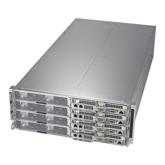
Page 13: Rear Features
Chapter 1: Introduction Rear Features The illustration below shows the features included on the rear of the chassis. PWS Slot2 PWS Slot1 Figure 1-3. Chassis Rear View Rear Chassis Features Item Feature Description Power Supply Dual 2000 Watt power supplies The chassis has eight rear fans for cooling. -
Page 14: Motherboard Layout
FatTwin F619H6-FT User's Manual 1.6 Motherboard Layout Below is a layout of the X11DPFF-SN with jumper, connector and LED locations shown. See the table on the following page for descriptions. For detailed descriptions, pinout information and jumper settings, refer to Chapter 4. -
Page 15: Quick Reference Table
Chapter 1: Introduction Quick Reference Table Jumper Description Default Setting JBT1 CMOS Clear Open (Normal) JPME2 ME Manufacturing Mode Pins 1-2 (Normal) JWD1 Watch Dog Timer Enable Pins 1-2 (Reset) Connector Description Battery (BT1) Onboard CMOS battery CPU1 Slot1 PCI-E (JPCEI4) PCI-E 3.0 x16 slot supported by CPU1 CPU1 Slot2 PCI-E (Slot 2) PCI-E 3.0 x8 slot supported by CPU1... - Page 16 FatTwin F619H6-FT User's Manual #F-1 #M-1 #E-1 #L-1 #D-1 #K-1 VR13 VR13 #C-1 #J-1 PHASE PHASE #B-1 #H-1 #A-1 #G-1 Proccessor Proccessor PECI: 30 PECI: 30 SOCKET ID:0 SOCKET ID:1 DMI3 DMI3 PCI-E X4 X2 G3 PCI-E X8 G3 PCI-E X16 G3...
-
Page 17: Chapter 2 Server Installation
Chapter 2: Server Installation Chapter 2 Server Installation 2.1 Overview This chapter provides advice and instructions for mounting your system in a server rack. If your system is not already fully integrated with processors, system memory etc., refer to Chapter 4 for details on installing those specific components. Caution: Electrostatic Discharge (ESD) can damage electronic components. -
Page 18: Server Precautions
FatTwin F619H6-FT User's Manual • In single rack installations, stabilizers should be attached to the rack. In multiple rack in- stallations, the racks should be coupled together. • Always make sure the rack is stable before extending a server or other component from the rack. -
Page 19: Circuit Overloading
Chapter 2: Server Installation Note: Insert each of the four nodes into the chassis from the bottom to the top. Circuit Overloading Consideration should be given to the connection of the equipment to the power supply circuitry and the effect that any possible overloading of circuits might have on overcurrent protection and power supply wiring. -
Page 20: Rack Mounting Instructions
FatTwin F619H6-FT User's Manual 2.3 Rack Mounting Instructions This section provides information on installing the chassis into a rack unit with the rails provided. There are a variety of rack units on the market, which may mean that the assembly procedure will differ slightly from the instructions provided. -
Page 21: Identifying The Sections Of The Rack Rails
Chapter 2: Server Installation Identifying the Sections of the Rack Rails The chassis package includes two rail assemblies in the rack mounting kit. Each assembly consists of two sections: A front section which secures to the front post of the rack and a rear section which adjusts in length and secures to the rear post of the rack. -
Page 22: Installing The Rails On A Rack
FatTwin F619H6-FT User's Manual Installing the Rails on a Rack Installing the Rails 1. Adjust the length of both rails as described on the previous page. 2. Align the front section of the outer rail with the slots on the front post of the rack. Secure the front of the outer rail to the rack with two screws. -
Page 23: Chassis Installation
Chapter 2: Server Installation Chassis Installation Installing the Chassis into a Rack 1. Confirm that the rails are correctly installed on the rack. 2. Align the bottom of the chassis with the bottom of the rails. 3. Insert the chassis into the rails, keeping the pressure even on both sides, pushing the chassis into the rack until it clicks into the locked position. -
Page 24: Chapter 3 Maintenance And Component Installation
FatTwin F619H6-FT User's Manual Chapter 3 Maintenance and Component Installation This chapter provides instructions on installing and replacing main system components. To prevent compatibility issues, only use components that match the specifications and/or part numbers given. Installation or replacement of most components require that power first be removed from the system. -
Page 25: Removing Nodes From The Chassis
Chapter 3: Maintenance and Component Installation Removing Nodes from the Chassis Each of the four individual motherboard nodes may be removed from the chassis. Note that any time a node is removed from the chassis, the hard drives located in the node will shut- down. -
Page 26: Installing And Removing Hard Drives
Refer to the charts below and on the following pages for your specific chassis configuration. These instructions apply to fixed 3.5" hard drives. Caution: Enterprise level hard disk drives are recommended for use in Supermicro chassis and servers. For information on recommended HDDs, visit the Supermicro website at http://www. -
Page 27: Replacing Fixed 3.5" Hard Drives
Chapter 3: Maintenance and Component Installation Replacing Fixed 3.5" Hard Drives Replacing a Fixed 3.5" Hard Drive 1. Power down the node with the operating system and remove the cord from the rear of the power supply as described in Section 3-1. Remove the node from the chassis and remove the node cover as described previously in this section. -
Page 28: Node Configuration
FatTwin F619H6-FT User's Manual Node Configuration The four F414IS4 chassis nodes are configured as illustrated above. In addition to the node components shown, there are eight exhaust fans and two power supplies located in the rear of the chassis body. -
Page 29: Removing And Installing The Backplane
Chapter 3: Maintenance and Component Installation Removing and Installing the Backplane The F414IS4 backplane is located under the hard drives on the front left side of each node as shown in Figure 6-5. Although backplane failure rarely occurs, in the event of a backplane failure, follow the instructions below. -
Page 30: Power Adapter Board Replacement
FatTwin F619H6-FT User's Manual Power Adapter Board Replacement Each of the nodes includes a power adapter board, which connects it to the chassis. In the unlikely event of a failure of the power adapter board, replacement is simple and requires only a Phillips head screwdriver. -
Page 31: Installing Expansion Cards
Chapter 3: Maintenance and Component Installation Installing Expansion Cards PCI-E Slot Setup The nodes of some F414IS4 chassis models support two low-profile PCI-E expansion cards. To install the low-profile expansion cards follow the instructions on the following pages. Low-Profile PCI-E Slot Cover Figure 3-7. -
Page 32: Installing A Low-Profile Expansion Card
FatTwin F619H6-FT User's Manual Installing a Low-Profile Expansion Card The F414IS4 chassis supports two low-profile expansion cards in each of the four nodes for a total of eight expansion cards in the chassis. Each expansion card connects to the motherboard with a riser card. - Page 33 Chapter 3: Maintenance and Component Installation Figure 3-8. Removing the Riser Card Bracket from the Node...
-
Page 34: Replacing Exhaust Fans
FatTwin F619H6-FT User's Manual Replacing Exhaust Fans Eight rear exhaust fans provide cooling for the nodes in the F414IS4 chassis. These fans circulate air through the nodes as a means of lowering the internal temperature. The F414IS4 exhaust fans are easily removed from the chassis without tools. There is no need to uninstall any other parts when replacing fans. - Page 35 Chapter 3: Maintenance and Component Installation Squeeze the Release Tabs Figure 3-10. Removing the System Fans from the Fan Housing...
-
Page 36: Replacing The Power Supply
FatTwin F619H6-FT User's Manual Replacing the Power Supply The F414IS4 chassis includes dual 2000 Watt power supplies. This power supply is auto- switching capable. This enables it to automatically sense and operate at a 100v to 240v input voltage. An amber light will be illuminated on the power supply when the power is off. An illuminated green light indicates that the power supply is operating. -
Page 37: Power Supply Replacement
The F414IS4 chassis utilizes two redundant power supplies. In the unlikely event that the power supply unit needs to be replaced, one power supply can be removed, without powering down the system. Replacement units can be ordered directly from Supermicro (see the contact information in the Preface of this manual). -
Page 38: Motherboard Components
CPU socket cap is in place and none of the socket pins are bent; otherwise, contact your retailer immediately. • Refer to the Supermicro website for updates on CPU support. The Processor (The 81xx/61xx/51xx/41xx/31xx Processor) Note: All graphics, drawings and pictures shown in this manual are for illustration only. -
Page 39: Overview Of The Processor Socket Assembly
Chapter 3: Maintenance and Component Installation Overview of the Processor Socket Assembly The processor socket assembly contains 1) the 81xx/61xx/51xx/41xx/31xx processor 2) CPU/ heatsink carrier, 3) dust cover, and 4) CPU socket. The 81xx/61xx/51xx/41xx/31xx Processor 2. CPU/Heatsink Carrier 3. Dust Cover 4. -
Page 40: Overview Of The Processor Heatsink Module
FatTwin F619H6-FT User's Manual Overview of the Processor Heatsink Module The processor heatsink module (PHM) contains 1) a passive heatsink, 2) a CPU/heatsink carrier, and 3) The 81xx/61xx/51xx/41xx/31xx processor. 1. Passive Heatsink 2. CPU/Heatsink Carrier 81xx/61xx/51xx/41xx/31xx Processor Processor Heatsink Module... -
Page 41: Preparing The Cpu Socket For Installation
Chapter 3: Maintenance and Component Installation Preparing the CPU Socket for Installation This motherboard comes with the CPU socket pre-assembled in the factory. The CPU socket contains 1) a dust cover, 2) a socket bracket, 3) the CPU (LGA3647) socket, and 4) a back plate. -
Page 42: Attaching The Processor To The Cpu/Heatsink Carrier
FatTwin F619H6-FT User's Manual Attaching the Processor to the CPU/Heatsink Carrier To properly install the CPU onto the CPU/heatsink carrier, please follow the steps below. Installing the CPU onto the CPU/heatsink 1. Locate Pin 1 (Notch A), Notch B, and Notch C on the CPU and locate Pin 1 (Notch A), Notch B, and Notch C on the CPU/heatsink carrier. -
Page 43: Attaching The Cpu/Carrier Assembly To The Passive Heatsink To Form The Processor Heatsink Module (Phm)
Chapter 3: Maintenance and Component Installation Attaching the CPU/Carrier Assembly to the Passive Heatsink to Form the Processor Heatsink Module (PHM) After you have made a CPU/carrier assembly, please follow the steps below to mount the assembly onto the heatsink to create the Processor Heatsink Module (PHM). 1. -
Page 44: Installing The Processor Heatsink Module (Phm)
FatTwin F619H6-FT User's Manual Installing the Processor Heatsink Module (PHM) 1. Once you have assembled the processor heatsink module (PHM) by following the instructions listed on the previous page, align the processor heatsink module with the CPU socket on the motherboard. -
Page 45: Removing The Processor Heatsink Module (Phm)
Chapter 3: Maintenance and Component Installation Removing the Processor Heatsink Module (PHM) Before starting to remove the processor heatsink module (PHM), unplug power cord from the power outlet. 1. Using a T30-size star driver, turn the screws on the PHM counterclockwise to loosen it from the socket, starting with screw marked #4 (in the sequence of 4, 3, 2, 1). -
Page 46: Memory Support And Installation
2666 DRx4 16 GB 32 GB 2666 QRX4 2H-64GB 2666 RDIMM 3Ds 8RX4 4H-128GB 2666 LRDIMM QRx4 32 GB 64 GB 2666 QRX4 2H-64GB 2666 LRDIMM 8Rx4 4H-128 GB 2666 Check the Supermicro website for possible updates to memory support. -
Page 47: Memory Population Guidelines
Then, if using two DIMMs per channel, install the second DIMM in the black slot. The following memory population sequence table was created based on guidelines provided by Intel to support Supermicro motherboards. The diagram is for illustrative purposes; your motherboard may look different. - Page 48 FatTwin F619H6-FT User's Manual Memory Population for X11 DP Motherboard, 12 DIMM Slots When 1 CPU is Memory Population Sequence used: 1 CPU & 1 DIMM CPU1: P1-DIMMA1 1 CPU & 2 DIMMs CPU1: P1-DIMMA1/P1-DIMMD1 1 CPU & 3 DIMMs CPU1: P1-DIMMC1/P1-DIMMB1/P1-DIMMA1 1 CPU &...
-
Page 49: Installing Memory
Chapter 3: Maintenance and Component Installation Installing Memory ESD Precautions Electrostatic Discharge (ESD) can damage electronic com ponents including memory modules. To avoid damaging DIMM modules, it is important to handle them carefully. The following measures are generally sufficient. • Use a grounded wrist strap designed to prevent static discharge. -
Page 50: Motherboard Battery
Chapter 3: Maintenance and Component Installation Motherboard Battery The motherboard uses non-volatile memory to retain system information when system power is removed. This memory is powered by a lithium battery residing on the motherboard. Replacing the Battery Begin by removing power from the system as described in section 3.1. 1. -
Page 51: Chapter 4 Motherboard Connections
Chapter 4: Motherboard Connections Chapter 4 Motherboard Connections This section describes the connections on the motherboard and provides pinout definitions. Note that depending on how the system is configured, not all connections are required. The LEDs on the motherboard are also described here. A severboard layout indicating component locations may be found in Chapter 1. -
Page 52: Headers And Connectors
FatTwin F619H6-FT User's Manual 8-Pin HDD Power Connectors Two 8-pin HDD power connectors, located at HDD_PWR1/2, provide power to HDD devices. Connect appropriate power cables to use HDD power connectors. See the table below for pin definitions. 8-pin Power HDD_PWR1/2... - Page 53 The JTPM1 header is used to connect a Trusted Platform Module (TPM)/Port 80 card, which is available from Supermicro. A TPM/Port 80 module is a security device that supports encryption and authentication in hard drives. It allows the motherboard to deny access if the TPM associated with the hard drive is not installed in the system.
- Page 54 FatTwin F619H6-FT User's Manual PCI-E/SATA M.2 Hybrid Slots This motherboard has two PCI-E/SATA Hybrid M.2 slots located at M.2-HC0 (J30)/M.2-HC1 (J31). The M.2, formerly known as "Next Generation Form Factor (NGFF)", replaces a mini PCI-E/SATA device and supports a variety of card sizes. M.2 offers increased functionality and improved spatial efficiency.
-
Page 55: Front I/O Ports
Chapter 4: Motherboard Connections 4.3 Front I/O Ports See the figure below for the locations and descriptions of the various I/O ports on the front of the motherboard. X11DPFF-SN Rev. 1.00 Figure 4-1. Front Panel I/O Port Locations and Definitions Front Panel I/O Ports Description No. - Page 56 UID LED. Please note that the UID switch can also be triggered via IPMI on the motherboard. For more information, please refer to the IPMI User's Guide posted on our website at http://www.supermicro.com.) UID Switch...
- Page 57 Chapter 4: Motherboard Connections Super I/O Module (SIOM) A Supermicro proprietary SIOM (Super I/O Module) connector, supported by CPU1, is located at SIOM in your system. This SIOM slot supports PCI-E 3.0 x16 add-on cards. Connect your PCI-E devices via appropriate cables to this slot for PCI-E I/O support. For your system to work properly, please use the PCI-E devices that are fully compliant with the PCI-E standard only.
-
Page 58: Jumpers
FatTwin F619H6-FT User's Manual 4.4 Jumpers Explanation of Jumpers To modify the operation of the motherboard, jumpers are used to choose between optional settings. Jumpers create shorts between two pins to change the function associated with it. Pin 1 is identified with a square solder pad on the printed circuit board. See the motherboard layout page for jumper locations. -
Page 59: Led Indicators
Chapter 4: Motherboard Connections ME Manufacturing Mode Close pins 1 and 2 of JPME2 to bypass SPI flash security and force the system to use the ME Manufacturing Mode, which will allow you to flash the system firmware from a host server to modify system settings. - Page 60 FatTwin F619H6-FT User's Manual HDD Activity LED An HDD Activity LED is located at HDD_LED1 on the on the motherboard. When this LED is blinking, your hard drive devices are active. See the table below for the LED status. HDD Activity LED Indicator...
-
Page 61: Chapter 5 Software
USB/SATA DVD drive, or a USB flash drive, or the IPMI KVM console. 2. Retrieve the proper RST/RSTe driver. Go to the Supermicro web page for your motherboard and click on "Download the Latest Drivers and Utilities", select the proper driver, and copy it to a USB flash drive. - Page 62 FatTwin F619H6-FT User's Manual 4. During Windows Setup, continue to the dialog where you select the drives on which to install Windows. If the disk you want to use is not listed, click on “Load driver” link at the bottom left corner.
-
Page 63: Driver Installation
The Supermicro website contains drivers and utilities for your system at https://www. supermicro.com/wdl/driver. Some of these must be installed, such as the chipset driver. After accessing the website, go into the CDR_Images (in the parent directory of the above link) and locate the ISO file for your motherboard. Download this file to to a USB flash drive or a DVD. -
Page 64: Superdoctor ® 5
5.3 SuperDoctor ® The Supermicro SuperDoctor 5 is a program that functions in a command-line or web-based interface for Windows and Linux operating systems. The program monitors such system health information as CPU temperature, system voltages, system power consumption, fan speed, and provides alerts via email or Simple Network Management Protocol (SNMP). -
Page 65: Chapter 6 Uefi Bios
Chapter 4: UEFI BIOS Chapter 6 UEFI BIOS 6.1 Introduction This chapter describes the AMIBIOS™ setup utility for the X11DPFF-SN motherboard. The BIOS ROM is stored on a chip and can be easily upgraded using a flash program. Note: Due to periodic changes to the BIOS, some settings may have been added or deleted and might not yet be recorded in this manual. -
Page 66: Main Setup
FatTwin F619H6-FT User's Manual 6.2 Main Setup When you first enter the AMI BIOS setup utility, you will enter the Main setup screen. You can always return to the Main setup screen by selecting the Main tab on the top of the screen. - Page 67 Chapter 4: UEFI BIOS CPLD Version This item displays the version of the CPLD (Complex-Programmable Logical Device) used in the system. Memory Information Total Memory This item displays the total size of memory available in the system.
-
Page 68: Advanced Setup Configurations
FatTwin F619H6-FT User's Manual 6.3 Advanced Setup Configurations Use the arrow keys to select the Advanced submenu and press <Enter> to access the submenu items. Warning: Take Caution when changing the Advanced settings. An incorrect value, an incorrect DRAM frequency, or an incorrect BIOS timing setting may cause the system to malfunction. - Page 69 Chapter 4: UEFI BIOS Option ROM Messages Use this feature to set the display mode for Option ROM message settings. Select Keep Current to use the current AddOn ROM display setting. Select Force BIOS to use the display mode that is set by the system BIOS. The options are Force BIOS and Keep Current. Bootup NumLock State Use this feature to set the Power-on state for the Numlock key.
- Page 70 FatTwin F619H6-FT User's Manual Restore on AC Power Loss Use this feature to set the power state after a power outage. Select Power-Off for the system power to remain off after a power loss. Select Power-On for the system power to be turned on after a power loss. Select Last State to allow the system to resume its last power state before a power loss.
- Page 71 Chapter 4: UEFI BIOS Hyper-Threading (ALL) Select Enable to use Intel Hyper-Threading Technology to enhance CPU performance. The options are Enable and Disable. Core Enabled Use this feature to enable or disable CPU cores in the processor specified by the user. Enter 0 to enable all cores available in the processor.
- Page 72 FatTwin F619H6-FT User's Manual DCU (Data Cache Unit) IP Prefetcher If this feature is set to Enable, the IP prefetcher in the DCU (Data Cache Unit) will prefetch IP addresses to improve network connectivity and system performance. The options are Enable and Disable.
- Page 73 Chapter 4: UEFI BIOS CPU P State Control (Available when "Power Technology" is set to Custom) SpeedStep (PStates) EIST (Enhanced Intel SpeedStep Technology) allows the system to automatically adjust processor voltage and core frequency in an effort to reduce power consumption and heat dissipation.
- Page 74 FatTwin F619H6-FT User's Manual Enhanced Halt State (C1E) Select Enable to enable "Enhanced Halt State" support, which will significantly reduce the CPU's power consumption by minimizing CPU's clock cycles and reduce voltage during a "Halt State." The options are Disable and Enable.
- Page 75 Chapter 4: UEFI BIOS Degrade Precedence Use this feature to select the degrading precedence option for UPI (Ultra Path Interconnect) connections. Select Topology Precedent to degrade UPI features if system options are in conflict. Select Feature Precedent to degrade UPI topology if system options are in conflict. The options are Topology Precedence and Feature Precedence.
- Page 76 FatTwin F619H6-FT User's Manual LLC Dead Line Alloc Select Enable to opportunistically fill the deadlines in LLC (Last Level Cache). The options are Enable, Disable, and Auto. Isoc Mode Select Enable to enable Isochronous support to meet QoS (Quality of Service) requirements.
- Page 77 Chapter 4: UEFI BIOS Enable ADR (Available when an NVDIMM is detected) Select Enable for ADR (Automatic Diagnostic Repository) support to enhance memory performance. The options are Enable and Disable. Erase-Arm NVDIMMs (Available when an NVDIMM is detected & the item above: Enable ADR is set to Enable) If this feature is set to Enable, the function that arms the NVDIMMs for save operations in the event of a power loss will be removed.
- Page 78 FatTwin F619H6-FT User's Manual Memory Topology This item displays the information of onboard memory modules as detected by the BIOS. • P1DIMMA1/P1DIMMB1/P1DIMMC1/P1DIMMD1/P1DIMME1/P1DIMMF1 • P2DIMMA1/P2DIMMB1/P2DIMMC1/P2DIMMD1/P2DIMME1/P2DIMMF1 Memory RAS (Reliability_Availability_Serviceability) Configuration Use this submenu to configure the following Memory RAS settings.
- Page 79 Chapter 4: UEFI BIOS Correctable Error Threshold Use this item to enter the threshold value for correctable memory errors. The default setting is 100. Intel Run Sure (Available when this feature is supported by the CPU) Select Enable to support Intel® Run Sure Technology to further enhance critical data protection and to increase system uptime and resiliency.
- Page 80 FatTwin F619H6-FT User's Manual IIO Configuration EV DFX (Device Function On-Hide) Features When this feature is set to Enable, the EV_DFX Lock Bits that are located in a processor will always remain clear during electric tuning. The options are Disable and Enable.
- Page 81 Chapter 4: UEFI BIOS IOAT Configuration Disable TPH (TLP Processing Hint) TPH is used for data-tagging with a destination ID among other important attributes. It can send critical data to a particular cache without writing through to memory. Select No in this item for TLP Processing Hint support, which will allow a "TPL request"...
- Page 82 FatTwin F619H6-FT User's Manual ATS (Available when the item: Intel VT for Directed I/O ((VT-d)) is set to Enable) Select Enable to enable ATS (Address Translation Services) support for the Non-Iscoh VT-d engine to enhance system performance. The options are Enable and Disable.
- Page 83 Chapter 4: UEFI BIOS VMD port 3C~VMD port 3D (Available when the device is detected by the system) Select Enable to use the Intel Volume Management Device Technology for this specific root port. The options are Disable and Enable. Hot Plug Capable (Available when the device is detected by the system) Use this feature to enable hot plug support for PCI-E root ports 3A~3D.
- Page 84 FatTwin F619H6-FT User's Manual Intel® VMD for Volume Management Device Select Enable to use the Intel Volume Management Device Technology for this stack. The options are Disable and Enable. *If the item "Intel VMD for Volume Management Device" above is set to Enable, the following...
- Page 85 Chapter 4: UEFI BIOS PCI-E PLL SSC Select Enable for PCH PCI-E Spread Spectrum Clocking support, which will allow the BIOS to monitor and attempt to reduce the level of Electromagnetic Interference caused by the components whenever needed. The options are Enable and Disable. Server ME (Management Engine) Configuration ...
- Page 86 FatTwin F619H6-FT User's Manual Aggressive Link Power Management When this item is set to Enabled, the SATA AHCI controller manages the power use of the SATA link. The controller will put the link in a low power mode during an extended period of I/O inactivity, and will return the link to an active state when I/O activity resumes.
- Page 87 Chapter 4: UEFI BIOS sSATA RSTe Boot Info (Available when the item: "Configure sSATA as" is set to RAID) Select Enable to provide the full int13h support for sSATA controller attached devices. The options are Disable and Enable. Aggressive Link Power Management When this item is set to Enable, the sSATA AHCI controller manages the power use of the SATA link.
- Page 88 FatTwin F619H6-FT User's Manual SR-IOV Support (Available if the system supports Single-Root Virtualization) Select Enabled for Single-Root IO Virtualization support. The options are Enabled and Disabled. MMIO High Base Use this feature to select the base memory size according to memory-address mapping for the IO hub.
- Page 89 Chapter 4: UEFI BIOS Onboard Video Option ROM Use this feature to select the Onboard Video Option ROM type. The options are Disabled, Legacy and EFI. Network Stack Configuration Network Stack Select Enabled to enable PXE (Preboot Execution Environment) or UEFI (Unified Extensible Firmware Interface) for network stack support.
- Page 90 FatTwin F619H6-FT User's Manual Super IO Configuration Super IO Chip AST2500 Serial Port 1 Configuration Serial Port 1 Select Enabled to enable the onboard serial port specified by the user. The options are Enabled and Disabled. Device Settings (Not Available when Serial Port 1 is set to Disabled.) This feature displays the base I/O port address and the Interrupt Request address of a serial port specified by the user.
- Page 91 Chapter 4: UEFI BIOS Serial Port Console Redirection COM 1 Console Redirection Select Enabled to enable COM Port 1 for Console Redirection, which will allow a client machine to be connected to a host machine at a remote site for networking. The options are Enabled and Disabled.
- Page 92 FatTwin F619H6-FT User's Manual Flow Control Use this feature to set the flow control for Console Redirection to prevent data loss caused by buffer overflow. Send a "Stop" signal to stop sending data when the receiving buffer is full. Send a "Start" signal to start sending data when the receiving buffer is empty. The options are None and Hardware RTS/CTS.
- Page 93 Chapter 4: UEFI BIOS Console Redirection Settings (for SOL/COM2) Use this feature to specify how the host computer will exchange data with the client computer, which is the remote computer used by the user. Terminal Type Use this feature to select the target terminal emulation type for Console Redirection. Select VT100 to use the ASCII Character set.
- Page 94 FatTwin F619H6-FT User's Manual Recorder Mode Select Enabled to capture the data displayed on a terminal and send it as text messages to a remote server. The options are Disabled and Enabled. Resolution 100x31 Select Enabled for extended-terminal resolution support. The options are Disabled and Enabled.
- Page 95 Chapter 4: UEFI BIOS (EMS) Console Redirection Settings Out-of-Band Management Port The feature selects a serial port in a client server to be used by the Windows Emergency Management Services (EMS) to communicate with a remote host server. The options are COM1 (Console Redirection) and SOL (Console Redirection).
- Page 96 FatTwin F619H6-FT User's Manual High Precision Event Timer Select Enabled to activate the High Precision Event Timer (HPET) that produces periodic interrupts at a much higher frequency than a Real-time Clock (RTC) does in synchronizing multimedia streams, providing smooth playback and reducing the dependency on other timestamp calculation devices, such as an x86 RDTSC Instruction embedded in the CPU.
- Page 97 Chapter 4: UEFI BIOS Security Device Support If this feature and the TPM jumper (JPT1), if available, are both enabled, the onboard security (TPM) device will be enabled in the BIOS to enhance data integrity and system security. Please note that the OS will not show the security device. Neither TCG EFI protocol nor INT1A interaction will be available for use.
- Page 98 Notes. 1: If the option for this item (TXT Support) is set to Enabled, be sure to disable EV DFX (Device Function On-Hide) support for the system to work properly. (EV DFX is under "IIO Configuration" in the "Chipset/North Bridge" submenu). 2: For more information on TPM, please refer to the TPM manual at http://www.supermicro.com/manuals/other. iSCSI Configuration ...
-
Page 99: Event Logs
Chapter 4: UEFI BIOS 6.4 Event Logs Use this feature to configure Event Log settings. Change SMBIOS Event Log Settings Enabling/Disabling Options SMBIOS Event Log Select Enabled to enable SMBIOS (System Management BIOS) Event Logging during system boot. The options are Enabled and Disabled. Erasing Settings Erase Event Log (Available when the item: SMBIOS Event Log is set to Enabled) Select Enabled to erase all error events in the SMBIOS (System Management BIOS) log... - Page 100 FatTwin F619H6-FT User's Manual When Log is Full (Available when the item: SMBIOS Event Log is set to Enabled) Select Erase Immediately to immediately erase all errors in the SMBIOS event log when the event log is full. Select Do Nothing for the system to do nothing when the SMBIOS event log is full.
-
Page 101: Ipmi
Chapter 4: UEFI BIOS 6.5 IPMI Use this feature to configure Intelligent Platform Management Interface (IPMI) settings. When you select this submenu and press the <Enter> key, the following information will display: • BMC Firmware Revision: This feature indicates the firmware revision of the BMC (Base- board Management Controller) used in your system. - Page 102 FatTwin F619H6-FT User's Manual Erase SEL (Available when the item: SEL Components is set to Enabled) Select Yes, On next reset to erase all system event logs upon next system reboot. Select Yes, On every reset to erase all system event logs upon each system reboot. Select No to keep all system event logs after each system reboot.
- Page 103 Chapter 4: UEFI BIOS IPMI Network Link Status This item displays the IPMI Network Link status. The default setting is Dedicated LAN. Configuration Address Source Use this feature to select the IP address source for this computer. If Static is selected, you will need to know the IP address of this computer and enter it to the system manually in the field.
-
Page 104: Security Settings
FatTwin F619H6-FT User's Manual 6.6 Security Settings This menu allows the user to configure the following security settings for the system. Administrator Password Use this feature to set the administrator password which is required to enter the BIOS setup utility. The length of the password should be from 3 characters to 20 characters long. - Page 105 Chapter 4: UEFI BIOS Secure Boot When you select this submenu and press the <Enter> key, the following items will display: • System Mode • Secure Boot • Vendor Keys Secure Boot If this feature is set to Enabled, Secure Boot will be activated when a Platform Key (PK) is entered.
- Page 106 FatTwin F619H6-FT User's Manual Platform Key (PK) This feature allows the user to enter and configure a set of values to be used as a platform firmware key for the system. This set of values also indicate the size, the keys numbers, and the key source of the Platform Key.
-
Page 107: Boot Settings
Chapter 4: UEFI BIOS 6.7 Boot Settings Use this feature to configure Boot Settings: Boot Mode Select Use this feature to select the type of devices to be used for system boot. The options are Legacy, UEFI (Unified Extensible Firmware Interface), and Dual. Legacy to EFI Support Select Enabled for the system to boot from an EFI OS when the Legacy OS fails. - Page 108 FatTwin F619H6-FT User's Manual • Boot Option #1 - Boot Option #8 *When the item above -"Boot Mode Select" is set to UEFI, the following items will be display for configuration: • Boot Option #1 - Boot Option #9 Add New Boot Option This feature allows the user to add a new boot option to the boot priority features for your system.
- Page 109 Chapter 4: UEFI BIOS Delete Boot Option Use this feature to remove an EFI boot option from the boot priority list. Delete Driver Option Use this item to select a boot driver to delete from the boot priority list. Delete Drive Option Select the target boot driver to delete from the boot priority list.
-
Page 110: Save & Exit
FatTwin F619H6-FT User's Manual 6.8 Save & Exit Select the Save & Exit tab from the BIOS setup screen to configure the settings below. Save Options Discard Changes and Exit Select this option to quit the BIOS setup without making any permanent changes to the system configuration and reboot the computer. - Page 111 Chapter 4: UEFI BIOS Discard Changes Select this option and press <Enter> to discard all the changes and return to the AMI BIOS setup utility. Default Options Restore Optimized Defaults To set this feature, select Restore Defaults from the Exit menu and press <Enter> to load manufacturer default settings which are intended for maximum system performance but not for maximum stability.
-
Page 112: Appendix A Bios Error Codes
FatTwin F619H6-FT User's Manual Appendix A BIOS Error Codes A-1 BIOS Error Beep (POST) Codes During the POST (Power-On Self-Test) routines, which are performed each time the system is powered on, errors may occur. Non-fatal errors are those which, in most cases, allow the system to continue the boot-up process. - Page 113 When BIOS performs the Power On Self Test, it writes checkpoint codes to I/O port 0080h. If the computer cannot complete the boot process, a diagnostic card can be attached to the computer to read I/O port 0080h (Supermicro p/n AOC-LPC80-20). For information on AMI updates, please refer to http://www.ami.com/products/.
-
Page 114: Appendix B Standardized Warning Statements For Ac Systems
Supermicro's Technical Support department for assistance. Only certified technicians should attempt to install or configure components. Read this appendix in its entirety before installing or configuring components in the Supermicro chassis. These warnings may also be found on our website at http://www.supermicro.com/about/... - Page 115 Appendix B: Standardized Warning Statements Warnung WICHTIGE SICHERHEITSHINWEISE Dieses Warnsymbol bedeutet Gefahr. Sie befinden sich in einer Situation, die zu Verletzungen führen kann. Machen Sie sich vor der Arbeit mit Geräten mit den Gefahren elektrischer Schaltungen und den üblichen Verfahren zur Vorbeugung vor Unfällen vertraut. Suchen Sie mit der am Ende jeder Warnung angegebenen Anweisungsnummer nach der jeweiligen Übersetzung in den übersetzten Sicherheitshinweisen, die zusammen mit diesem Gerät ausgeliefert wurden.
- Page 116 FatTwin F619H6-FT User's Manual . ٌ ا ك ً ف حالة و ٌ يك أى تتسبب ف اصابة جسذ ة ٌ هذا الزهز ع ٌ خطز !تحذ ز قبل أى تعول عىل أي هعذات،يك عىل علن بالوخاطز ال ا ٌجوة عي الذوائز...
- Page 117 Appendix B: Standardized Warning Statements Warnung Vor dem Anschließen des Systems an die Stromquelle die Installationsanweisungen lesen. ¡Advertencia! Lea las instrucciones de instalación antes de conectar el sistema a la red de alimentación. Attention Avant de brancher le système sur la source d'alimentation, consulter les directives d'installation. .יש...
- Page 118 FatTwin F619H6-FT User's Manual Warnung Dieses Produkt ist darauf angewiesen, dass im Gebäude ein Kurzschluss- bzw. Überstromschutz installiert ist. Stellen Sie sicher, dass der Nennwert der Schutzvorrichtung nicht mehr als: 250 V, 20 A beträgt. ¡Advertencia! Este equipo utiliza el sistema de protección contra cortocircuitos (o sobrecorrientes) del edificio.
- Page 119 Appendix B: Standardized Warning Statements Power Disconnection Warning Warning! The system must be disconnected from all sources of power and the power cord removed from the power supply module(s) before accessing the chassis interior to install or remove system components. 電源切断の警告...
- Page 120 FatTwin F619H6-FT User's Manual אזהרה מפני ניתוק חשמלי !אזהרה יש לנתק את המערכת מכל מקורות החשמל ויש להסיר את כבל החשמלי מהספק .לפני גישה לחלק הפנימי של המארז לצורך התקנת או הסרת רכיבים يجب فصم اننظاو من جميع مصادر انطاقت وإ ز انت سهك انكهرباء من وحدة امداد...
- Page 121 Appendix B: Standardized Warning Statements Attention Il est vivement recommandé de confier l'installation, le remplacement et la maintenance de ces équipements à des personnels qualifiés et expérimentés. !אזהרה .צוות מוסמך בלבד רשאי להתקין, להחליף את הציוד או לתת שירות עבור הציוד واملدربيه...
- Page 122 FatTwin F619H6-FT User's Manual Warnung Diese Einheit ist zur Installation in Bereichen mit beschränktem Zutritt vorgesehen. Der Zutritt zu derartigen Bereichen ist nur mit einem Spezialwerkzeug, Schloss und Schlüssel oder einer sonstigen Sicherheitsvorkehrung möglich. ¡Advertencia! Esta unidad ha sido diseñada para instalación en áreas de acceso restringido. Sólo puede obtenerse acceso a una de estas áreas mediante la utilización de una herramienta especial,...
- Page 123 Appendix B: Standardized Warning Statements Battery Handling Warning! There is the danger of explosion if the battery is replaced incorrectly. Replace the battery only with the same or equivalent type recommended by the manufacturer. Dispose of used batteries according to the manufacturer's instructions 電池の取り扱い...
- Page 124 FatTwin F619H6-FT User's Manual هناك خطر من انفجار يف حالة اسحبذال البطارية بطريقة غري صحيحة فعليل اسحبذال البطارية فقط بنفس النىع أو ما يعادلها مام أوصث به الرشمة املصنعة جخلص من البطاريات املسحعملة وفقا لحعليامت الرشمة الصانعة 경고! 배터리가 올바르게 교체되지 않으면 폭발의 위험이 있습니다. 기존 배터리와 동일하거나 제...
- Page 125 Appendix B: Standardized Warning Statements ¡Advertencia! Puede que esta unidad tenga más de una conexión para fuentes de alimentación. Para cortar por completo el suministro de energía, deben desconectarse todas las conexiones. Attention Cette unité peut avoir plus d'une connexion d'alimentation. Pour supprimer toute tension et tout courant électrique de l'unité, toutes les connexions d'alimentation doivent être débranchées.
- Page 126 FatTwin F619H6-FT User's Manual Backplane Voltage Warning! Hazardous voltage or energy is present on the backplane when the system is operating. Use caution when servicing. バックプレーンの電圧 システムの稼働中は危険な電圧または電力が、 バックプレーン上にかかっています。 修理する際には注意く ださい。 警告 当系统正在进行时,背板上有很危险的电压或能量,进行维修时务必小心。 警告 當系統正在進行時,背板上有危險的電壓或能量,進行維修時務必小心。 Warnung Wenn das System in Betrieb ist, treten auf der Rückwandplatine gefährliche Spannungen oder Energien auf.
- Page 127 Appendix B: Standardized Warning Statements هناك خطز مه التيار الكهزبايئ أوالطاقة املىجىدة عىل اللىحة عندما يكىن النظام يعمل كه حذ ر ا عند خدمة هذا الجهاس 경고! 시스템이 동작 중일 때 후면판 (Backplane)에는 위험한 전압이나 에너지가 발생 합니다. 서비스 작업 시 주의하십시오. Waarschuwing Een gevaarlijke spanning of energie is aanwezig op de backplane wanneer het systeem in gebruik is.
- Page 128 FatTwin F619H6-FT User's Manual תיאום חוקי החשמל הארצי !אזהרה .התקנת הציוד חייבת להיות תואמת לחוקי החשמל המקומיים והארציים تركيب املعدات الكهربائية يجب أن ميتثل للقىاويه املحلية والىطىية املتعلقة بالكهرباء 경고! 현 지역 및 국가의 전기 규정에 따라 장비를 설치해야 합니다.
- Page 129 Appendix B: Standardized Warning Statements Attention La mise au rebut ou le recyclage de ce produit sont généralement soumis à des lois et/ou directives de respect de l'environnement. Renseignez-vous auprès de l'organisme compétent. סילוק המוצר !אזהרה .סילוק סופי של מוצר זה חייב להיות בהתאם להנחיות וחוקי המדינה التخلص...
- Page 130 FatTwin F619H6-FT User's Manual Warnung Gefährlich Bewegende Teile. Von den bewegenden Lüfterblätter fern halten. Die Lüfter drehen sich u. U. noch, wenn die Lüfterbaugruppe aus dem Chassis genommen wird. Halten Sie Finger, Schraubendreher und andere Gegenstände von den Öffnungen des Lüftergehäuses entfernt.
- Page 131 Verbindungskabeln, Stromkabeln und/oder Adapater, die Ihre örtlichen Sicherheitsstandards einhalten. Der Gebrauch von anderen Kabeln und Adapter können Fehlfunktionen oder Feuer verursachen. Die Richtlinien untersagen das Nutzen von UL oder CAS zertifizierten Kabeln (mit UL/CSA gekennzeichnet), an Geräten oder Produkten die nicht mit Supermicro gekennzeichnet sind.
- Page 132 .قيرح وأ لطع يف ببستي دق ىرخأ تالوحمو تالباك يأ مادختسا .ميلسلا سباقلاو لصوملا مجح لبق نم ةدمتعملا تالباكلا مادختسا تادعملاو ةيئابرهكلا ةزهجألل ةمالسلا نوناق رظحيUL وأCSA ( ةمالع لمحت يتلاوUL/CSA) لبق نم ةددحملاو ةينعملا تاجتنملا ريغ ىرخأ تادعم يأ عمSupermicro.
- Page 133 사항을 준수하여 제공되거나 지정된 연결 혹은 구매 케이블, 전원 케이블 및 AC 어댑터를 사용하십시오. 다른 케이블이나 어댑터를 사용하면 오작동이나 화재가 발생할 수 있습니다. 전기 용품 안전법은 UL 또는 CSA 인증 케이블 (코드에 UL / CSA가 표시된 케이블)을 Supermicro 가 지정한 제품 이외의 전기 장치에 사용하는 것을 금지합니다. Stroomkabel en AC-Adapter...
-
Page 134: Appendix C System Specifications
FatTwin F619H6-FT User's Manual Appendix C System Specifications Processors Dual 81xx/61xx/51xx/41xx/31xx in an Socket P0 type sockets for each node. Note: Please refer to the motherboard specifications pages on our website for updates to supported processors. Chipset C621 chipset BIOS 32 MB SPI AMI BIOS®... - Page 135 Appendix C: System Specifications Operating Environment Operating Temperature: 10º to 35º C (50º to 95º F) Non-operating Temperature: -40º to 60º C (-40º to 140º F) Operating Relative Humidity: 8% to 90% (non-condensing) Non-operating Relative Humidity: 5% to 95% (non-condensing) Regulatory Compliance Electromagnetic Emissions: FCC Class A, EN 55032 Class A, EN 61000-3-2/3-3, CISPR 32 Class A Electromagnetic Immunity: EN 55024/CISPR 24, (EN 61000-4-2, EN 61000-4-3, EN 61000-4-4, EN 61000-4-5, EN 61000-4-6,...
-
Page 136: Appendix D Uefi Bios Recovery
Warning: Do not upgrade the BIOS unless your system has a BIOS-related issue. Flashing the wrong BIOS can cause irreparable damage to the system. In no event shall Supermicro be liable for direct, indirect, special, incidental, or consequential damages arising from a BIOS update. - Page 137 Note: If you cannot locate the "Super.ROM" file in your drive disk, visit our website at www. supermicro.com to download the BIOS package. Extract the BIOS binary image into a USB flash device and rename it "Super.ROM" for the BIOS recovery use.
- Page 138 FatTwin F619H6-FT User's Manual 3. After locating the healthy BIOS binary image, the system will enter the BIOS Recovery menu as shown below. Note: At this point, you may decide if you want to start the BIOS recovery. If you decide to proceed with BIOS recovery, follow the procedures below.
- Page 139 Appendix D: UEFI BIOS Recovery 5. After the BIOS recovery process is complete, press any key to reboot the system. 6. Using a different system, extract the BIOS package into a USB flash drive. 7. Press <Del> continuously during system boot to enter the BIOS Setup utility. From the top of the tool bar, select Boot to enter the submenu.
- Page 140 FatTwin F619H6-FT User's Manual 8. When the UEFI Shell prompt appears, type fs# to change the device directory path. Go to the directory that contains the BIOS package you extracted earlier from Step 6. Enter flash.nsh BIOSname.### at the prompt to start the BIOS update process.
Need help?
Do you have a question about the FatTwin F619H6-FT and is the answer not in the manual?
Questions and answers