
Related Manuals for STIEBEL ELTRON TEGREON SNAP S 15 ST


Summary of Contents for STIEBEL ELTRON TEGREON SNAP S 15 ST
- Page 1 INSTALLATION Photovoltaic installation system for flat roofs » TEGREON SNAP S 15 ST » TEGREON SNAP S 15 ST ER » TEGREON SNAP S 15 MI » TEGREON SNAP S 15 MI ER » TEGREON SNAP S 15 EN » TEGREON SNAP S 15 EN ER...
- Page 2 Contents Introduction Brief description On these instructions Warning notices TEGREON SNAP S Safety Technical description System overview Components Technical data Important assembly notes Application conditions Assembly preparation Assembling aid and required tools Expansion joints On the assembly descriptions Planning of the module area Corner clamping assembly Laying and assembly of the first mounting frame rows...
- Page 3 1. Introduction 1.1. Brief description The TEGREON SNAP S flat roof system is a rugged frame system for the assembly of PV modules on flat roofs. The TEGREON SNAP S system allows for the connection of several rows of modules in East-West direction.
- Page 4 1.2. On these instructions User groups Subject This manual describes the assembly of the TEGREON SNAP S flat roof system as well as any system-specific • specialist staff information on planning, components and safety • instructed staff instructions. The drawings in the first part of the manual show Specialist staff the assembly of the system for the corner clamping Specialist staff are those persons who, due to their...
- Page 5 1.3. Warning notices The complete general safety regulations for the frame systems are included in the further applicable The warning notices used in this Installation Manual document "Installation Manual - General Information". indicate safety-relevant information. They include: Read this document with care and always observe the notices contained - use the frame only in compliance with its intended •...
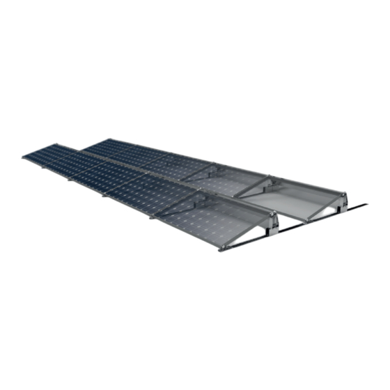
- Page 6 2. Technical description The design of each system part may vary. It depends on: 2.1 System overview • the type of roof The following illustration shows all system parts. • the type of module • the number of modules • the local conditions Ill.
- Page 7 2.2 Components The following illustration shows all parts of the TEGREON SNAP S frame which can be included in the scope of delivery. The exact scope of delivery as well as the number of individual frame parts depend on your order. Building protection mats can be ordered as an option but are required for assembly.
- Page 8 2.3 Technical data Place of application Flat roof The static loading capability of the roof must always be checked Building height Depends on the wind zone and terrain category PV modules Framed, frameless Module widths 900–1050 mm Module arrangement In connection Module orientation Transverse Pitch...
- Page 9 3. Important assembly notes 3.2 Assembly preparation The manufacturer recommends gathering information 3.1 Application conditions on the on-site conditions before ordering TEGREON SNAP S. In particular, you should familiarise yourself Ballast stones are applied on the ground rails in order with: to secure the mounted flat roof system.
- Page 10 3.5 On the assembly description Danger to life due to damage to the roof The following chapters describe all steps necessary for the planning and assembly of TEGREON SNAP S in DANGER Excessive load may severely damage their correct order. Chapter 5 describes the assembly the roof! steps for the corner clamping of the modules at the short side, chapter 6 includes the additional assembly...
- Page 11 Two building protection mats for each elevation must be placed under each ground rail (one each under every front foot and every back support). If additional ballast support components such as ballast profiles or L-profiles are used, additional building protection mats are required.
- Page 12 Assembly steps: 16 Nm • Preassemble the short ground rails (60 mm) at the front support. • Push the next rail piece to the short rail piece without clearance and mount it with the front sup- port. • Align the preassembled ground rails at right angles to the alignment line using a cord.
- Page 13 Danger to life due to falling parts! Parts falling from the roof may DANGER cause severe injury or death! • Seal off the danger zone on the ground prior to starting assembly work in order to prevent persons from being injured by falling parts! •...
- Page 14 5.2. Mounting the back support Foot lug Assembly steps: • The back support is mounted using the supplied gauge. To this end, the gauge is placed between the two lugs. • Tighten the back support as well as the front support on the ground rail.
- Page 15 5.3 Mounting the next front support Assembly steps: • Push the next front support onto the front ground rail with the front support protruding into the front 1710 mm (15°) 1360 mm ground rail by 60 mm. 1450 mm (10°) 60 mm •...
- Page 16 5.4 Applying ballast Assembly steps: Before finally mounting the modules, ballast must be applied. Depending on the amount of the ballast, there are two variants for applying ballast to the TEGREON SNAP S system. Picture 5.4 – 1 Both variants as well as their assembly are presented in this chapter.
- Page 17 Applying ballast with additional L-profiles Assembly steps: • Prepare the T-head bolts and nuts at the on the L- profile for ballast. • The L-profile for ballast on the back support is flush-with the back support. • Irregularities can be compensated by means of the oblong hole in the ballast L-angle.
- Page 18 The lugs at the inside of the SNAP are designed such that any mechanical release is ruled out once the screw has been tightened. So if you want to remove the SNAP from the rail by pressing it together and lifting it up, you must first unscrew the Allen screw to above the lug.
- Page 19 5.6 Mounting the back sheet The back sheet can be mounted without screws using the clamping claw. Assembly steps: • Apply the back sheet with its bottom the ground rails and slide it towards the back support until the up- per side of the back sheet fits the plane at the back support.
- Page 20 Picture 6.1 – 3 Picture 6.1 – 4 Picture 6.1 – 5 Picture 6.1 – 6 Rail clamping of the modules...
- Page 21 6.2 Elongating the rails Assembly steps: • Each rail can be elongated with the inner connector. • To do so, you must insert the inner connector into the rail until the centre press cut touches the end of the rail, and then push the second rail until the press cuts are reached.
- Page 22 Deutschland Verkauf Tel. 05531 702-110 | Fax 05531 702-95108 | info-center@stiebel-eltron.de STIEBEL ELTRON GmbH & Co. KG Kundendienst Tel. 05531 702-111 | Fax 05531 702-95890 | kundendienst@stiebel-eltron.de Dr.-Stiebel-Straße 33 | 37603 Holzminden Ersatzteilverkauf Tel. 05531 702-120 | Fax 05531 702-95335 | ersatzteile@stiebel-eltron.de Tel.
Need help?
Do you have a question about the TEGREON SNAP S 15 ST and is the answer not in the manual?
Questions and answers