Table of Contents
Advertisement
Quick Links
Monitoring Technique
VARIMETER IMD
Insulation monitor
RN 5893
RN 5893
Product Description
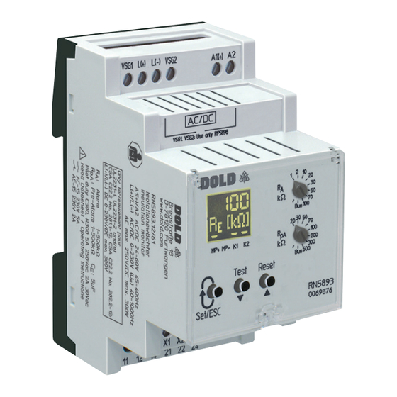
The insulation monitor RN 5893 of the VARIMETER IMD family is a solution
for optimal insulation monitoring of modern IT systems. The device can be
used in the most flexible way for AC, DC and AC/DC systems. Mains areas
of applications are non-earthed DC charging stations for electric vehicles
with mains voltages up to DC 1000 V. The adjustment of the setting values
is simple and user friendly done on 2 rotary switches on the front of the
device. Via display and LEDs the measured value, device parameters
and device status are indicated easy to read. With a sealable transparent
cover the device is protectet against manipulation. The RN 5893 has an
additonal Modbus RTU-interface. All measured values, device states
and parameters can be read out, set and parameterized. All functions
available on the device can also be operated via Modbus.
Function Diagram
By default:
Indicator rel. K1 (11, 12, 14) = Insulation fault-alarm + device fault and
Indicator rel. K2 (21, 22, 24) = Insulation fault-pre-alarm + device fault:
U H
R
E
Earth fault
R
pA
R
A
Hysteresis function
21-24
Open circuit operation
21-22
21-24
De-energized on trip
21-22
11-14
Open circuit operation
11-12
11-14
De-energized on trip
11-12
Manual reset
Reset
21-24
Open circuit operation
21-22
21-24
De-energized on trip
21-22
11-14
Open circuit operation
11-12
11-14
De-energized on trip
11-12
All Technical Data in this list relate to the state at the moment of edition. We reserve the right
for technical improvements and changes at any time.
Coupling device
RP 5898
t
t
M11593
Translation
of the original instructions
Your Advantages
• Suitable for DC charging stations for electric vehicles acc. to
IEC/EN 61851-23:2014/AC:2016-06
• Preventive fire and system protection
• Detection of symmetric and asymmetric insulation faults
• Quick fault localisation through selective earth fault detection to L+ and L-
• Universal application in non-earthed AC, DC, AC/DC networks
up to AC max. 250 V or DC max. 300 V
• With connection facility of an external coupling device
RP 5898 for voltages up to AC 690 V / DC 1000 V
• RN 5893: Very fast reaction time ≤ 1 s
RN 5893/010: Reaction time < 10 s
• Optimised insulation resistance monitoring also during
mains voltage variation
• Easy adjustment of response values and setting parameter via
rotational switch and menu display or via Modbus RTU-interface
• RN 5893: Suitable for leakage capacitances up to 5 µF
RN 58930/010: Suitable for leakage capacitances up to 30 µF
• Monitoring also with voltage-free mains
• Measuring circuit L(+)/L(-) with broken wire detection (can be switched off)
• Protective conductor PE1/PE2 with broken wire detection
(can't be switched off)
• 2 parameterizable changeover contacts (for insulation fault pre-alarm,
insulation fault-alarm, insulation fault-alarm on DC+/DC- or
device fault) each galvanic separated
• With galvanic separated Modbus RTU interface
Features
• Insulation monitoring according to IEC/EN 61557-8
• 2 separate adjustable response thresholds
(using e.g. for pre-alarm and alarm)
• Setting value pre-alarm: 1 kΩ ... 500 kΩ
• Setting value alarm: 1 kΩ ... 500 kΩ
• Energized or de-energized on trip can be selected for indicator relay
• Display for indication of measured value, device parameters and
device status
• Manual device self-test (automatic device self-test)
• Alarm storage selectable
• Protection against manipulation by sealable transparent cover
• External control input for combined test- / reset-button
with additional Stop of the measuring function
• 2 wide voltage input for auxiliary voltage
• Width 52.5 mm
Approvals and Markings
AC/DC
Canada / USA
Applications
Insulation monitoring of:
• Non-earthed AC, DC, AC/DC networks
• DC charging stations for electric vehicles
• UPS systems
• Networks with frequency inverters
• Battery networks
• Networks with direct current drives
• Hybrid and battery-powered vehicles
• Mobile generator sets
1
17.04.24 en / 869A
Advertisement
Table of Contents

Related Manuals for DOLD VARIMETER IMD RN 5893


Summary of Contents for DOLD VARIMETER IMD RN 5893
- Page 1 Monitoring Technique Translation of the original instructions VARIMETER IMD Insulation monitor RN 5893 Your Advantages • Suitable for DC charging stations for electric vehicles acc. to IEC/EN 61851-23:2014/AC:2016-06 • Preventive fire and system protection Coupling device • Detection of symmetric and asymmetric insulation faults •...
-
Page 2: Measuring Circuit
Function Function Disable the measuring function The device is supplied with DC auxiliary voltage via terminals A1(+) / A2. Switching on the auxiliary voltage (Power-On) is followed by an internal Using the external control input X1/X2 or a Modbus command the measuring self-test for 12 s (see „Device test functions“). -
Page 3: External Control Input
Function Function Device test functions Behaviour with internal device faults Principally, 2 different test functions are implemented: The "self-test" and If internal device faults were detected during the test function, the display the "expanded test": backlight changes into red and an error messages (failure code: „Int.1“) is The device self-tests automatically after power-on. - Page 4 Function Function Programming/setting of parameters/set-up of the insulation monitor Programming/setting of parameters/set-up of the insulation monitor (via Modbus) The response values for alarm and pre-alarm can be adjusted via 2 rotary switches „R “ and „R “ on the front of the device.New setting are immediately If the device should be parameterized via Modbus, the rotary switches "R "...
-
Page 5: Circuit Diagram
Circuit Diagram Indicators Connection L(+) L(-) VSG1 VSG2 (+) A2 measuring ciruit Auxiliary coupling device voltage L(+) L(-) X1 X2 11 12 14 21 22 24 PE1 PE2 M12852 Connection Terminals Terminal designation Signal description A1(+), A2 Auxiliary voltage AC or DC Connection for measuring ciruit or L(+), L(-), VSG1, VSG2 Connection for coupling device... -
Page 6: Display Indication
Indicators Indicators The colour of the backlight indicates the operating status of the device. Display-Indication Measuring- resp. display value Off: No auxiliary voltage connected Green: Normal operation (Insulation resistance in healthy state) Insulating resistance in kΩ resp. MΩ Red: Alarm (measured value below alarm response value, („----“... - Page 7 Error Indication Notes Risk of electrocution! Display-Indication Failure cause Failure recovery Danger to life or risk of serious injuries. WARNING • Disconnect the system and device from the power supply and ensure they remain disconnected during electrical installation. Check • The display of the voltage is not in real time. The Value on the display is Broken wire detection measuring circuit updated at the end of a measuring cycle.
- Page 8 Running chart Press button Press button Taster „Set/ESC“ „Set/ESC“ > 2s Press button Scroll Down „▼“ Start Press button Scroll Up „▲“ Parameter 1: Parameter 1: Parameter 1: Broken wire detect in Broken wire detect in Broken wire detect in measuring circuit measuring circuit measuring circuit...
- Page 9 Technical Data Technical Data Measuring ciruit L(+)/L(-) to PE1/PE2 (without coupling device) Meas. ciruit L1(+)/L2(-) to PE1/PE2 (with coupling device RP 5898) Nominal voltage U Nominal voltage U AC / DC 0 ... 230 V AC 0 ... 690 V Max.
-
Page 10: Vibration Resistance
Technical Data Technical Data Auxiliary voltage input A1(+)/A2 Degree of protection Housing: IP 30 IEC/EN 60529 Terminals: IP 20 IEC/EN 60529 Nom. Voltage Voltage range Frequency range Housing: Thermpolastic with V0 behaviour AC 19 ... 68 V 45 … 400 Hz; DC 48 % W* according to UL subject 94 AC/DC 24 ... - Page 11 Standard Types Accessories RN 5893.12/61 AC/DC 24 … 60 V RP5898/61 Article number: 0069876 Article number: 0066944 • Auxiliary voltage: AC/DC 24 … 60 V • Coupling device for RN 5893 RN 5893.12/61 AC/DC 100 … 240 V • Extension of nominal voltage range U Article number: 0069877 to DC 1000 V, AC 690 V...
-
Page 12: Connection Examples
Connection Examples Ungrounded mains Ungrounded mains RP5898: 3 AC 0...760V 40...1000Hz 3/N AC 400V/230V 40...1000Hz Setting of type of network: Setting of type of network L1(+) L2(-) 3N AC External coupling device: External coupling device: RP5898 VSG1 L(+) L(-) VSG2 A1(+) VSG1 L(+) - Page 13 Connection Examples Single phase mains, isolated from earth Single phase mains, isolated from earth AC 0...250V 40...1000Hz RP5898: AC 0...760V 40...1000Hz Setting of type of network Setting of type of network: L1(+) L2(-) External coupling device: External coupling device: RP5898 VSG1 L(+) L(-)
-
Page 14: Function Codes
Bus Interface Protocol Modbus Seriell RTU Adress 1 to 99 Baud rate 1200, 2400, 4800, 9600, 19200, 38400, 57600, 115200 Baud Data bit Stop bit Parity None More information about the interface, wiring rules, device identification and communication monitoring can be found in the Modbus user manual. Function-Codes At RN 5893 the following function codes are implemented: Function-... - Page 15 Parameter Table Coils Register- Protocol- Value Initial Name Description Data type Access rights Adress Adress range value Reset 0x0000 0x0000 No Function Write / read 0xFF00 Error acknowledgement device error Device reset 0x0000 0x0000 No Function Write / read 0xFF00 Device restart Reserved 0x0000...
- Page 16 0 = Off UINT16 Write / read 1 = On E. Dold & Söhne GmbH & Co. KG • D-78120 Furtwangen • Bregstraße 18 • Phone +49 7723 654-0 • Fax +49 7723 654356 dold-relays@dold.com • www.dold.com 17.04.24 en / 869A...
Need help?
Do you have a question about the VARIMETER IMD RN 5893 and is the answer not in the manual?
Questions and answers