Table of Contents
Advertisement
Quick Links
Monitoring Technique
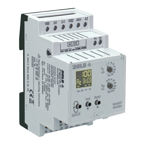
VARIMETER IMD
Insulation monitor
RN 5897/011
RN 5897/011
Product Description
The insulation monitor RN 5897/011 of the VARIMETER IMD family
provides best and up to date insulation monitoring of modern IT systems
in an optimum and state of the art way fulfilling the relevant standards.
The device can be used in the most flexible way for AC, DC and AC/DC
systems even with large leakage capacity to earth (PE). The adjustment of
the setting values is simple and user friendly done on 2 rotary switches on
the front of the device. Via display and LEDs the measured value, device
parameters and device status are indicated easy to read. With a sealable
transparent cover the device is protectet against manipulation. The
RN 5987/011 has an additonal Modbus RTU-interface. All measured
values, device states and parameters can be read out, set and
parameterized. All functions available on the device can also be operated
via Modbus.
Function Diagram
U H
R
E
Earth fault
R
pA
R
A
Hysteresis function
21-24
Open circuit operation
21-22
21-24
De-energized on trip
21-22
11-14
Open circuit operation
11-12
11-14
De-energized on trip
11-12
Manual reset
Reset
21-24
Open circuit operation
21-22
21-24
De-energized on trip
21-22
11-14
Open circuit operation
11-12
11-14
De-energized on trip
11-12
All Technical Data in this list relate to the state at the moment of edition. We reserve the right
for technical improvements and changes at any time.
Coupling devices
RL 5898
RP 5898
M11593
Your Advantages
• Preventive fire and system protection
• Detection of symmetric and asymmetric insulation faults
• Quick fault localisation through selective earth fault detection to L+
and L-
• Universal application in non-earthed AC, DC, AC/DC networks
up to AC max. 250 V or DC max. 300 V
• With connection facility of an external coupling device RL 5898
for voltages up to AC 400 V / DC 500 V or
RP 5898 for voltages up to AC 690 V / DC 1000 V
• Easy adjustment of response values and setting parameter via
rotational switch and menu display or via Modbus RTU-interface
• Suitable for large leakage capacitances up to 1000 µF
• Optimised reaction time for large leakage capacitances
• Monitoring also with voltage-free mains
• Measuring circuit L(+)/L(-) with broken wire detection (can be switched off)
• Protective conductor PE1/PE2 with broken wire detection
(can't be switched off)
• 2 changeover contacts each for insulation failures-Pre-alarm and -alarm
each galvanically isolated
• With galvanic separated Modbus RTU interface
Features
• Insulation monitoring according to IEC/EN 61557-8
• Trigger output for insulation fault locating system
• 2 separate adjustable response thresholds
(using e.g. for pre-Alarm and Alarm)
• Setting range of 1st response value (Pre-Alarm): 1 kΩ ... 2 MΩ
• Setting range of 2nd response value (Alarm): 1 kΩ ... 2 MΩ
• Energized or de-energized on trip can be selected for indicator relay
• Display for indication of measured value, device parameters and
device status
• Setting the maximum leakage capacitance to shorten the response time
• Automatic and manual device self-test
• Alarm storage selectable
• Protection against manipulation by sealable transparent cover
• External control input for combined Test-/Reset-button
• 2 wide voltage input for auxiliary voltage
• Width 52.5 mm
Approvals and Markings
t
AC/DC
t
Applications
Insulation monitoring of:
• Non-earthed AC, DC, AC/DC networks
• UPS systems
• Networks with frequency inverters
• Battery networks
• Networks with direct current drives
• Hybrid and battery-powered vehicles
• Mobile generator sets
1
Original
30.06.23 de / 752A
Advertisement
Table of Contents

Subscribe to Our Youtube Channel
Related Manuals for DOLD VARIMETER IMD RN 5897/011


Summary of Contents for DOLD VARIMETER IMD RN 5897/011
- Page 1 Monitoring Technique Original VARIMETER IMD Insulation monitor RN 5897/011 Your Advantages • Preventive fire and system protection • Detection of symmetric and asymmetric insulation faults • Quick fault localisation through selective earth fault detection to L+ Coupling devices and L- •...
-
Page 2: Measuring Circuit
Function Function Via Modbus The device is supplied with DC auxiliary voltage via terminals A1(+) / A2. Switching on the auxiliary voltage (Power-On) is followed by an internal The locating current injector RR 5886 has also a Modbus RTU interface. self-test for 12 sec (see „Device test functions“). - Page 3 Function Function Behaviour with internal device faults The seventh parameter is the setting of the Modbus Baudrate ("kBaud"). If internal device faults were detected during the test function, the display backlight changes into red and an error messages (failure code: „Int.1“) Possible setting values are: is indicated.
-
Page 4: Signal Description
Default-Setting of Parameters Indicators Trigger Parameter Default-Set output Broken wire detect in measuring circuit Connection “Broken Wire Detect” measuring ciruit Auxiliary Storing insulation fault message coupling device voltage “Memory” Switching mode of output relays n.c. (normally closed) “Relay” de-energized on trip Power supply type “Net”... -
Page 5: Display Indication
Indicators Indicators The colour of the backlight indicates the operating status of the device. Display-Indication Measuring- resp. display value Off: No auxiliary voltage connected Insulating resistance in kΩ resp. MΩ Green: Normal operation (Insulation resistance in healthy state) („----“ complies RE ≥ 2 MΩ) Red: Alarm (measured value below alarm response value, device failure, connection failure) - Page 6 • The trigger output Y1/Y2 at RN 5897/011 is galvanic separated from the rest of the circuit. It determined to be connected to a DOLD insulation fault location system RR 5886 and RR 5887. Please do not connect external voltages.
- Page 7 Running chart Press button Press button „Set/ESC“ „Set/ESC“ >2s Press button Scroll Down „ ▼“ Set parameters Press button Scroll Up „ ▲“ Parameter 1: Parameter 1: Parameter 1: Broken wire detect in Broken wire detect in Broken wire detect in measuring circuit measuring circuit measuring circuit...
- Page 8 Technical Data Technical Data Measuring ciruit L(+)/L(-) to PE1/PE2 (without coupling device) Auxiliary voltage input A1(+)/A2 Nominal voltage U AC / DC 0 ... 230 V Nom. Voltage Voltage range Frequency range Max. voltage range U AC 0 ... 250 V AC 19 ...
-
Page 9: Vibration Resistance
Technical Data Classification to DIN EN 50155 Vibration and IEC/EN 61326-2-4 shock resistance: Electrostatic discharge (ESD): 8 kV (air) IEC/EN 61000-4-2 Category 1, Class B IEC/EN 61373 Service temperature classes: OT1 compliant HF irradiation: Protective coating of the PCB: No 80 MHz …... - Page 10 Accessories Accessories Flush mounting kit RL 5898/61 Order reference: KU 4087-150/0056598 Article number: 0068315 • Coupling device for RN 5897.12/011 • Extension of nominal voltage range U to DC 500 V, AC 400 V • Weight: Approx. 60 g • Dimensions - Width x height x depth: 35 x 90 x 71 mm For universal use with:...
-
Page 11: Connection Examples
Characteristics M11605 Connection Examples Ungrounded mains Ungrounded mains 3/N AC 400V/230V 16...1000Hz RL5898: 3 AC 0...440V 16...1000Hz RP5898: 3 AC 0...760V 16...1000Hz Setting of type of network 3N AC Setting of type of network: L1(+) L2(-) External coupling device: External coupling device: RL5898 VSG1 L(+) - Page 12 Connection Examples Single phase mains, isolated from earth Single phase mains, isolated from earth AC 0...250V 16...1000Hz RL5898: AC 0...440V 16...1000Hz RP5898: AC 0...760V 16...1000Hz Setting of type of network Setting of type of network: L1(+) L2(-) External coupling device: External coupling device: RL5898 VSG1...
-
Page 13: Function Codes
Bus Interface Protocol Modbus Seriell RTU Adress 1 to 99 Baud rate 1200, 2400, 4800, 9600, 19200, 38400, 57600, 115200 Baud Data bit Stop bit Parity None More information about the interface, wiring rules, device identification and communication monitoring can be found in the Modbus user manual. Function-Codes At RN 5897/011 the following function codes are implemented: Function-... - Page 14 Parameter table Coils Register- Protocol- Value Initial Name Description Data type Access rights Adress Adress range value Reset 0x0000 0x0000 No Function write / read 0xFF00 Error acknowledgement device error Device reset 0x0000 0x0000 No Function write / read 0xFF00 Device restart Reserved 0x0000...
- Page 15 Parameter Table Input Registers Register- Protocol- Value Name Description Data type Access rights Adress Adress range 30001 Device failure 0 … 12 0: No failure UINT16 read 1: Broken wire detection L(+)/L(-) 2: Broken wire detection PE1/PE2 3: Internal failure detected in test mode (Int. 1) 4: Parameter failures (Incorrect setting of potentiometers on the device) 9: Communication fault Modbus...
- Page 16 Bit 0 = Off UINT16 write /Read Bit 1 = RL 5898 or RP 5898 E. Dold & Söhne GmbH & Co. KG • D-78120 Furtwangen • Bregstraße 18 • Phone +49 7723 654-0 • Fax +49 7723 654356 dold-relays@dold.com • www.dold.com...
Need help?
Do you have a question about the VARIMETER IMD RN 5897/011 and is the answer not in the manual?
Questions and answers