DOLD VARIMETER IMD Series Translation Of The Original Instructions
Insulation monitor
Hide thumbs
Also See for VARIMETER IMD Series:
- Manual (16 pages) ,
- Translation of the original instructions (16 pages)
Table of Contents
Advertisement
Quick Links
Monitoring Technique
VARIMETER IMD
Insulation monitor
RN 5897/320
RN 5897/320
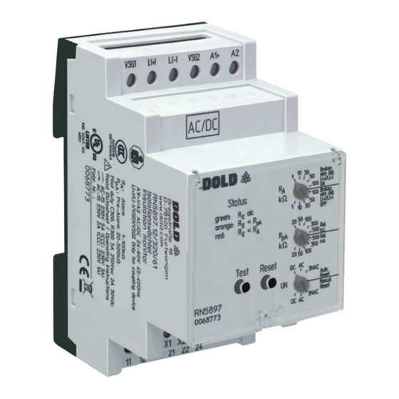
Product Description
The insulation monitor RN 5897/020 of the VARIMETER IMD family
provides best and up to date insulation monitoring of modern IT systems
in an optimum and state of the art way fulfilling the relevant standards.
The device can be used in the most flexible way for AC, DC and AC/
DC systems. Mains areas of applications are non-earthed DC charging
stations for electric vehicles with mains voltages up to DC 1000 V, that
need an extended temperature range. The connection to the monitored
voltage system is done via one of the coupling units. The setting of the
parameters and the switching values is done by simple and operator
friendly rotational switches on front of the device. The operating status is
indicated user friendly via a multicolour LED. With a sealable transparent
cover the device is protectet against manipulation.
Circuit Diagram
VSG1
L(+)
L(-)
A1(+)
VSG2
L(+) L(-)
11
U H
PE1
PE2
12
X1 X2
11 12 14 21 22 24
PE1
Connection Terminals
Terminal designation
Signal description
A1(+), A2
Auxiliarx voltage AC or DC
L(+), L(-), VSG1, VSG2
Connection for coupling device
PE1, PE2
Connection for protective conductor
Control input
(combined external Test- and Reset-input
X1, X2
with additional Stop of the measuring
function)
11, 12, 13
Alarm signal relay K1(1 changeover contact)
Prewarning signal relay K2 (1 changeover
21, 22, 23
contact)
All Technical Data in this list relate to the state at the moment of edition. We reserve the right
for technical improvements and changes at any time.
Coupling devices
RL 5898
RP 5898
A2
21
14
22
24
PE2
M11956_a
Translation
of the original instructions
Your Advantages
• Suitable for DC charging stations for electric vehicles acc. to
IEC/EN 61851-23:2014
• Insulation monitoring according to IEC/EN 61557-8
• Connection of an external coupling device RL 5898
for voltages up to AC 400 V / DC 500 V or
RP 5898 for voltages up to AC 690 V / DC 1000 V
• Extended operating temperature range of - 40 ... + 70 °C
• Very fast reaction time ≤ 1 s
• Optimised insulation resistance monitoring also during
mains voltage variation
• Self-test every full operating hours
• Preventive fire and system protection
• Detection of symmetric and asymmetric insulation faults
• Universal application in non-earthed AC, DC, AC/DC networks
• Easy adjustment of response values and setting parameter via
rotational switch
• Suitable for large leakage capacitances up to 5 µF
• Monitoring also with voltage-free mains
• Measuring circuit L1(+)/L2(-) with broken wire detection (can be switched off)
• Protective conductor PE1/PE2 with broken wire detection
(can't be switched off)
Features
• 2 separate adjustable response thresholds
(using e.g. for pre-alarm and Alarm)
• Setting range of 1st response value (Pre-alarm): 20 kΩ ... 500 kΩ
• Setting range of 2nd response value (alarm): 1 kΩ ... 100 kΩ
• 1 changeover contacts each for insulation failures-Pre-alarm and -alarm
• Energized or de-energized on trip can be selected for indicator relay
• With multicolour status LED to indicate the state of operation.
• Automatic and manual device self-test
• Alarm storage selectable
• Protection against manipulation by sealable transparent cover
• External control input for combined test- / reset-button
with additional Stop of the measuring function
• 3 wide voltage input for auxiliary voltage
• Additional coupling device is necessary
• Width 52.5 mm
Approvals and Markings
Canada / USA
Applications
Insulation monitoring of:
• Non-earthed AC, DC, AC/DC networks
• DC charging stations for electric vehicles
• UPS systems
• Networks with frequency inverters
• Battery networks
• Networks with direct current drives
• Hybrid and battery-powered vehicles
• Mobile generator sets
1
AC/DC
1)
RN 5897 only
06.05.21 en / 393A
Advertisement
Table of Contents

Subscribe to Our Youtube Channel
Related Manuals for DOLD VARIMETER IMD Series


Summary of Contents for DOLD VARIMETER IMD Series
- Page 1 Monitoring Technique VARIMETER IMD Translation Insulation monitor of the original instructions RN 5897/320 Your Advantages • Suitable for DC charging stations for electric vehicles acc. to IEC/EN 61851-23:2014 • Insulation monitoring according to IEC/EN 61557-8 Coupling devices • Connection of an external coupling device RL 5898 for voltages up to AC 400 V / DC 500 V or RP 5898 for voltages up to AC 690 V / DC 1000 V •...
-
Page 2: Measuring Circuit
Function Function The device is supplied with DC auxiliary voltage via terminals A1(+) / A2. Broken wire detection Switching on the auxiliary voltage (Power-On) is followed by an internal As described in section "Measuring circut", the measuring circuits L(1+)/ self-test for 12 s (see „Device test functions“). The test process is visible L2(-) and the protective conductors PE1/PE2 are constantly monitored for with the status LED. -
Page 3: Function Diagram
Function Function Diagram Behaviour with internal device faults If internal device faults were detected during the test function, the status LED flashes permanently red. The indicator relays K1 and K2 switch to the alarm state. Behavior on faulty connection Earth fault When detecting broken wire on terminals L1(+)/L2(-), the measurement is disabled. - Page 4 Indicators Error Indication Connection Auxiliary Flash code Coupling device voltage Failure cause Failure recovery Status-LED Check Broken wire detection measuring circuit on L(+)/L(-). L(+) and L (-) Check Broken wire detection protective earth on PE1/PE2. connections PE1 and PE2 Press test button again or restart the unit by interrupting the Internal failure continously...
-
Page 5: Vibration Resistance
Technical Data Technical Data General Data Meas. ciruit L1(+)/L2(-) to PE1/PE2 (with coupling device RL / RP 5898) RL 5898 RP 5898 Operating mode: Continuous operation Nominal voltage U AC 0 ... 400 V AC 0 ... 690 V Temperature range DC 0 ... -
Page 6: Switching Capacity
UL-Data Accessories Meas. ciruit L1(+)/L2(-) to PE1/PE2 (with coupling device RL / RP 5898) RL 5898/61 Article number: 0068315 RL 5898 RP 5898 • Coupling device for RN 5897.12/320 Max. voltage range U AC 0 ... 400 V AC 0 ... 600 V •... - Page 7 Accessories Flush mounting kit Order reference: KU 4087-150/0056598 For universal use with: · R-series devices of 17.5 to 105 mm width · Easy mounting 06.05.21 en / 393A...
-
Page 8: Connection Examples
• Control < 1.5 s: Reset function • Control > 10 s: Stop of measuring function E. Dold & Söhne GmbH & Co. KG • D-78120 Furtwangen • Bregstraße 18 • Phone +49 7723 654-0 • Fax +49 7723 654356 dold-relays@dold.com • www.dold.com...
Need help?
Do you have a question about the VARIMETER IMD Series and is the answer not in the manual?
Questions and answers