
Subscribe to Our Youtube Channel
Related Manuals for GeKaMac POWER TIG 2200 DC PULSE


Summary of Contents for GeKaMac POWER TIG 2200 DC PULSE
- Page 1 PoWer TIG 2200 and 2600 DC Pulse Users Manual Please Read and Understand This Manual Before Operating The Welding Machine www.gedikwelding.com...
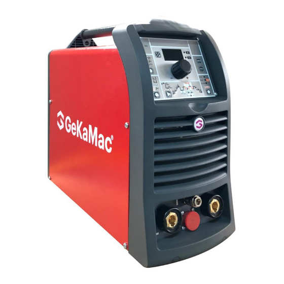
- Page 2 ENGLISH Description Introduction Description POWER TIG 2200 DC PULSE Powerful, compact, and light weight, the POWER TIG 2000 DC Features PULSE units represent the most innovative, high performance, and technically advanced single-phase inverter generators for Usage limits (IEC 60974-1) TIG welding to be found. The PFC (Power Factor Correction)
- Page 3 - Anti-sticking function to avoid the electrodes sticking. tion is signaled by “t° C” flashing on control panel display (for fur- POWER TIG 2200 DC PULSE ther information see the MTH / MTB control panel manual). After • The PFC device makes the wave form of the current absorbed si- several minutes the overheat cut-off rearms automatically and the welder is ready for use again.
- Page 4 “O”. Single-phase power Open the packaging Power TIG 2200 DC PULSE supply The system essentially consists of: Use the welder’s own plug to connect it up to the main power sup- •...
- Page 6 Interfacing accessories (optional) “RoboMAT 1” analogue / digital robot interface Fitted on the back of the POWER TIG 2600 DC PULSE welding machine (see example, Pos. 1, Fig. B). “RoboMAT 1” analogue / digital robot interface connection cable - Cutting robot or for automatic equipment Connect the cable to the analogue / digital interface as shown in figure (Pos.
- Page 7 TIG WELDING WITH “Lift” TYPE STRIKING 3) Make the adjustments and select the parameters on the con- 4a) Open the gas cylinder and flow regulator. trol panel (for further information see the MTH / MTB control 5a) Put the electrode at the point at which welding is to begin, put panel manual).
- Page 8 Original spare parts have been specially designed for our equip- ment. The use of non-original spare parts may cause variations in A6 kit for connecting non- standard GEKAMAC torches performance or reduce the foreseen level of safety. We decline all responsibility for the use of non-original spare parts.
- Page 9 FIG. G Digital interface PCB replacement The pointing out of any difficulties and their elimination • Unscrew the 4 screws fastening the front rack panel. • Remove the adjustment knob. The supply line is attributed with the cause of the most common •...
- Page 10 Wiring diagram Key to the electrical diagram Primary circuit thermistor Power supply connector 230V 50/60Hz Secondary circuit thermostat EMC capacitors Transformer Power supply connector for the cooling system Pressure switch TIG torch connector Secondary diode “Dual Boost Chopper” IGBT Digital display Encoder Gas solenoid valve Fuse...
- Page 11 POWER TIG 2200 DC PULSE...
- Page 12 POWER TIG 2600 DC PULSE...
- Page 13 PoWer TIG 2200 and 2600 DC Pulse Users Manual Please Read and Understand This Manual Before Operating The Welding Machine www.gedikwelding.com...
- Page 14 Spare parts list (POWER TIG 2200 DC PULSE) POWER TIG 2200 DC PULSE Pos. Description 352453 Front rack transparent visor 447845 POWER TIG 2200 DC PULSE membrane keyboard Ø29mm Knob without index 438888 GEKA logo sticker Ø20mm 468191 Front panel without GEKA logo sticker Ø20mm...
- Page 15 POWER TIG 2200 DC PULSE Description Pos. 377094 EMC filter PCB 413537 Auxiliary wiring 286036 "Dual Boost Chopper" IGBT 286038 "Full Bridge" IGBT 239995 HF transformer 419074 3x2 Poles female connector 403782 Terminal for 3x2 poles female connector 427683 HF filter...
- Page 16 POWER TIG 2200 DC PULSE Pos. Description 431331 Foot 404933 Base 352944 Dinse Insulation 449495 Internal metallic frame 463217 Transformer support 481402 Transformer 240234 Inductor 240232 PFC inductors 376930 Torch switch filter PCB 481946 Hall effect transformer 478786 Secondary thermostat...
- Page 17 EN Spare parts list (POWER TIG 2600 DC PULSE ) POWER TIG 2600 DC Pos. Description PULSE 352453 Front rack transparent visor 447867 MTH Membrane Keyboard POWER TIG 2600 DC PULSE 447860 MTH Membrane Keyboard POWER TIG 2600 DC PULSE 447863 MTB Membrane Keyboard POWER TIG 2600 DC PULSE Ø29mm Knob without index...
- Page 18 POWER TIG 2600 DC Pos. Description PULSE 413467 Auxiliary wiring RoboMat 1 – POWER TIG 2600 DC PULSE 413518 478867 Primary circuit thermistor 353052 Inverter PCB insulation 239989 HF transformer 376930 Torch filter with connector 427681 HF filter 352466 HF PCB box 377059 High frequency (HF) PCB 352468...
- Page 19 POWER TIG 2600 Pos. Description DC PULSE 431329 Foot 404912 Base 352944 Dinse Insulation 463218 Transformer support 481436 Transformer 449485 Internal metallic frame 481946 Current transducer 478848 Secondary circuit thermostat 455511 Secondary rectifier 423236 Secondary diode 425938 Gas solenoide valve 377153 Secondary circuit PCB (without diodes module) 377244K...
- Page 20 2) The type of device 3) The voltage and frequency read on the rating plate 4) The serial number of the same EXAMPLE N. 2 pieces code n. - for POWER TIG 2200 DC PULSE - 400 V -50/60 Hz - Serial number ............
- Page 21 Operator’s manual READ CAREFULLY...
- Page 22 ■ VRD ■ WELDING PROCESS The Voltage Reduction Device (VRD) is a The GEKAMAC welding machine offers 4 TIG/Electrode welding safety device that reduces the voltage. It processes. Each time the button is pushed, the welding machine prevents voltages forming on the output...
- Page 23 ■ WELDING MODE • When the torch button is pressed and released within less than The GEKAMAC welding machine offers 5 welding modes. Each 1 second the welding current goes to the CYCLE value ( I ), and time by repeating this operating you can move between the two cur-...
- Page 24 Slow pulsations (SLOW PULSE) PULSATION FREQUENCY f WARNING: NOT programmable when SLOW pulsation mode is WARNING: active. switched on and steady. L17 L10 L18 L19 WARNING: The operator can decide to TIG weld without using any pulsation mode. If this is the case, the 4 LEDs are switched off. ■...
- Page 25 5) To exit these functions hold the WELDING PARAMETERS Electrode welding (MMA) SELECTION key (T7) down for about 1 second, after which the DISPLAY INDICATION LED switches on and the welding 1) Start the welding machine by turning the power supply switch machine is once again ready to weld at the current indicated to position I.
- Page 26 “Lift DC” TIG welding with TIG LIFT DC welding with the manual gas valve TIG torches SPOT WELDING function active 1) Start the welding machine by turning the power supply switch 1) Start the welding machine by turning the power supply switch to position I.
- Page 27 TIG HF DC welding with TIG HF DC welding with “ColdTack” function active SPOT function active The“ColdTack” mode can be used for cold tacking in quick succes- Innovative TIG HF DC spot weld device that makes it possible to do precise, safe spot welding with little heat applied. The “Per- sion, to further extend the benefits of an individual point.
- Page 28 • Switch-off time (0.01 ÷ 2 sec) (L13 on flashing). One example of configuration could be t=1sec and n=3: this will generate 3 impulses each lasting 200 msec, separated by a 200 msec pause. 200ms 200ms weld TIG HF DC with “RCT” welding mode 2 stroke / 4 strokee TIG RCT “RUNNING COLD TACK”...
- Page 29 2) Start the welding machine by turning the power supply switch to position I. formation of the material. 3) The DISPLAY (D) shows the following message: Std (welder The GEKAMAC can be used for TIG pulsed welding in 4 differ- configured in STANDARD mode). ent modes: • SLOW PULSE •...
- Page 30 2B) FAST PULSE L10 L20 BASE CURRENT I TIG pulse welding with manual setting of parameters. 2200 2600 Press the PULSE key (T3) until the requited pulsation 1 ÷ 220 A 1 ÷ 260 A is active (FAST LED on). FAST SLOW L10 L19...
- Page 31 3B - FAST PULSE + CYCLE WELDING PARAMETERS with PULSE mode and Press the WELDING MODE SELECTION key CYCLE welding mode active (CYCLE LED on) (T6) until the CYCLE welding mode is active FAST (CYCLE LED on). SLOW When this welding mode is active it is possible to work at 2 differ- PULSE ent pulse current levels ( I and I...
- Page 32 2200 2600 1 ÷ 220 A 1 ÷ 260 A During TIG welding with HF ignition, the GEKAMAC units allow youto further modify the WELDING PARAMETERS, thereby provid-ing a more skilled welder and a more versatile welding L18 L20 LEVEL PEAK CURRENT I machine.Activation will only take place after the machine...
- Page 33 LED L5 flashing Welding machine in STANDARD (Std) configuration: AUTO 4 stroke function enabled During TIG welding with HF ignition, the GEKAMAC units allow you to modify the MINIMUM and MAXIMUM LIMITS for some LED L5 flashing WELD- ING PARAMETERS, thereby providing a more skilled See the WELDING MODE paragraph to see the differences be- welder anda more versatile welding machine.
- Page 34 Creating and memorising PROGRAMMED and/ automatic welding points or MANUAL welding The welding machine has scope for saving up to 99 WELDING PROGRAMMED WELDING PROGRAMS broken down into two categories: When the WELDING PROGRAM has been saved, the operator • F + 01÷99 = Free, non-saved programs. can weld using only pre-set values as they cannot edit any type •...
- Page 35 Calling up saved programs Activating the VRD device 1) Hold the “PRG” PROGRAM Key (T2) down (about 3 seconds) To activate the VRD device, which must be done when the weld- until the DISPLAY (D) shows the number of the program se- ing machine is switched off: lected flashing (e.g.
- Page 36 Energy saving Machine test menu This function manages correct functioning of the cooling fan and The machine test menu makes it possible to test functionality of cooling equipment that only run when strictly necessary, that is: the gas solenoid valve, the fan, and the cooling unit. •...
- Page 37 Automatic reset error. WARNING: The POWER TIG 2200 DC PULSE welding machine has a built-in electronic protective device to deal with fluctuations in mains voltage that switches the machine off automatically (voltage exceeding 300 V), without indicating any type of error or warn-ing message for the operator.
- Page 38 Gedik Welding Inc. Ankara Caddesi No: 306 Şeyhli 34906 Pendik - İstanbul / Turkey +90 216 378 50 00 • +90 216 378 20 44 www.gedikwelding.com...
Need help?
Do you have a question about the POWER TIG 2200 DC PULSE and is the answer not in the manual?
Questions and answers