Advertisement
Advertisement
Table of Contents

Subscribe to Our Youtube Channel
Related Manuals for Rohm BD28C57HFJ-EVK-001


Summary of Contents for Rohm BD28C57HFJ-EVK-001
- Page 1 Flyback method Isolated Output Power 48W BD28C57HFJ-EVK-001...
-
Page 2: High Voltage Safety Precautions
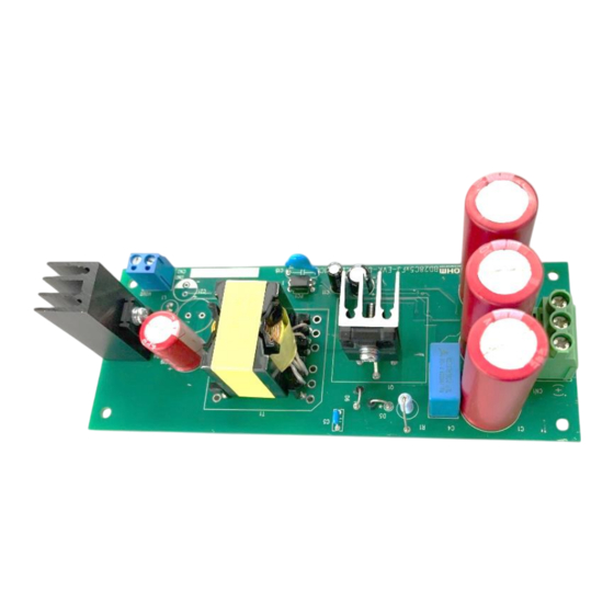
[8] Be sure to wear insulated gloves when handling is required during operation. After Use [9] The ROHM Evaluation Board contains the circuits which store the high voltage. Since it stores the charges even after the connected power circuits are cut, please discharge the electricity after using it, and please deal with it after confirming such electric discharge. - Page 3 The control IC used is the BD28C57HFJ, which is suitable for driving SiC MOSFET. The control method is current mode. The oscillation frequency is approximately 65 kHz, and the duty max is 50%. Figure 1. BD28C57HFJ-EVK-001 © 2024 ROHM Co., Ltd. No. 67UG086E Rev.001 1/15...
-
Page 4: Performance Specification
(Note 1) Adjust the operating time so that surface temperature of no component exceeds 105 ° C (Note 2) Do not consider spike noise Derating Ambient Temparature Ta (℃) Figure 2. Temperature derating curve © 2024 ROHM Co., Ltd. No. 67UG088E Rev.001 2/15 OCTOBER.2024... -
Page 5: Operation Procedure
(8) Make sure that the DC voltmeter reading is at the set voltage (24 V). (9) Electronic load switch is ON. DC Meter 24 V CN1-2 AC (N) CN1-2 AC (L) DC Power Power Supply Load Meter Figure 3. Diagram of How to Connect © 2024 ROHM Co., Ltd. No. 67UG086E Rev.001 3/15 NOVEMBER2024... -
Page 6: Application Circuit
The oscillation frequency is determined by R21 (12kΩ) and C9 (1000pF). It is set to approximately 65kHz. A leading edge blanking circuit is installed to prevent malfunction due to noise. The leading edge blanking circuit consists of Q2, R27, C14, and R28. Figure 4. Application Circuit © 2024 ROHM Co., Ltd. No. 67UG086E Rev.001 4/15 NOVEMBER2024... - Page 7 Error amplifier output pin Feedback signal output pin Primary side current sense pin RTCT Switching frequency setting pin GND pin Exernal MOS drive terminal pin Power supply input pin VREF 5VOutput pin © 2024 ROHM Co., Ltd. No. 67UG086E Rev.001 5/15 NOVEMBER2024...
-
Page 8: Measurement Data
Figure 7. Efficiency vs I 2. Line Regulation vs V 25.5 0.5 A 25.0 1.5 A 24.5 24.0 23.5 23.0 22.5 Figure 8. Line Regulation (V vs V Figure 9. Efficiency vs Input Voltage © 2024 ROHM Co., Ltd. No. 67UG086E Rev.001 6/15 NOVEMBER2024... - Page 9 2 A / Div Figure 12. Secondary Diode at V = 300 VDC, I = 2.0 A Figure 13. Secondary Diode at V = 900 VDC, I = 2.0 A © 2024 ROHM Co., Ltd. No. 67UG086E Rev.001 7/15 NOVEMBER2024...
- Page 10 10 A / Div 10 A / Div Figure 14. Output waveform during short circuit V = 300 Vdc Figure 15. Output waveform during short circuit V = 900 Vdc © 2024 ROHM Co., Ltd. No. 67UG086E Rev.001 8/15 NOVEMBER2024...
- Page 11 2 A / Div Figure 18. V = 930 VDC, I = switch 0 A / 2.0 A Figure 19. V = 900 VDC, I = switch 0 A / 2 A © 2024 ROHM Co., Ltd. No. 67UG086E Rev.001 9/15 NOVEMBER2024...
- Page 12 = 900 VDC, I = 2.0 A Temperature of Parts Surface They are measured after 20 minutes from applying a power supply. Table 2. Surface Temperature of Parts (Ta = 24.8 °C) © 2024 ROHM Co., Ltd. No. 67UG086E Rev.001 10/15 NOVEMBER2024...
- Page 13 BD28C57HFJ-EVK-001 User’s Guide Schematics = 300 VDC~900 VDC、V = 24 V 2.0 A Figure 22. BD28C57HFJ-EVK-001 Schematics © 2024 ROHM Co., Ltd. No. 67UG086E Rev.001 11/15 NOVEMBER2024...
-
Page 14: Parts List
MCR03EZPFX4701 Rohm 2.2 kΩ MCR03EZPFX2201 Rohm 6.8 kΩ MCR03EZPJ682 Rohm 100 Ω R57,R58 ESR25JPZPZJ101 Rohm 1.66 mH XE2870YA Alpa Trans 22 V UDZVTE1722B Rohm Materials may be changed without notifying. © 2024 ROHM Co., Ltd. No. 67UG086E Rev.001 12/15 NOVEMBER2024... - Page 15 BD28C57HFJ-EVK-001 User’s Guide Layout Size: 155 mm x 60 mm Figure 23. TOP Silkscreen (Top view) Figure 24. Bottom Layout (Top View) © 2024 ROHM Co., Ltd. No. 67UG086E Rev.001 13/15 NOVEMBER2024...
- Page 16 Winding Pin Turn Tape Wire Wire Number Layer Specification Start Finish COMPACT TEX-E / Φ0.30 COMPACT 2UEW / Φ0.35 COMPACT TEX-E / Φ0.20 COMPACT 2UEW / Φ0.35 COMPACT TEX-E / Φ0.30 © 2024 ROHM Co., Ltd. No. 67UG086E Rev.001 14/15 NOVEMBER2024...
-
Page 17: Revision History
BD28C57HFJ-EVK-001 User’s Guide Revision History Date Rev. Changes 12.November.2024 New Release © 2024 ROHM Co., Ltd. No. 67UG086E Rev.001 15/15 NOVEMBER2024... - Page 18 Specific Applications). Unless otherwise agreed in writing by ROHM in advance, ROHM shall not be in any way responsible or liable for any damages, expenses, or losses incurred by you or third parties arising from the use of ROHM Products for Specific Applications.
Need help?
Do you have a question about the BD28C57HFJ-EVK-001 and is the answer not in the manual?
Questions and answers