
Related Manuals for Daikin CVXM20B2V1B


Summary of Contents for Daikin CVXM20B2V1B
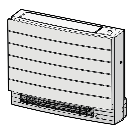
- Page 1 Installation manual Split system air conditioners CVXM20B2V1B FVXM25B2V1B FVXM35B2V1B Installation manual FVXM50B2V1B English Split system air conditioners FVXTM30B2V1B...
- Page 2 Technical engineering data ▪ A subset of the latest technical data is available on the regional Daikin website (publicly accessible). ▪ The full set of the latest technical data is available on the Daikin Business Portal (authentication required). Specific installer safety instructions Always observe the following safety instructions and regulations.
- Page 3 2 Specific installer safety instructions INFORMATION CAUTION ▪ Units CVXM-B, FVXM-B contains refrigerant leakage Piping and joints of a split system shall be made with sensor, special requirement for unit with refrigerant permanent joints when inside an occupied space except leakage sensor applies.
- Page 4 This could result in electrical shock or fire. INFORMATION: Declaration of conformity ▪ Daikin Industries Czech Republic s.r.o. declares that WARNING the radio equipment type inside of this unit is in Keep the interconnection wiring away from copper pipes compliance with Directive 2014/53/EU.
- Page 5 5 Unit installation Preparing the installation site INFORMATION ▪ The total refrigerant charge (m), the minimum floor WARNING area is (A ) limitation depends also on room height (H) and if the unit is installed in the LOWEST The appliance shall be stored as follows: UNDERGROUND FLOOR or in any OTHER FLOORS.
- Page 6 5 Unit installation The LOWEST UNDERGROUND LEVEL Floor-standing installation m (kg) H=≥2.2 m H=2.0 m H=1.8 m ≤1.842 No limitations 1.843 5.46 6.00 6.67 5.63 6.19 6.88 5.92 6.51 7.24 6.22 6.84 7.60 6.51 7.17 7.96 6.81 7.49 8.32 7.11 7.82 8.69 7.40 8.14 9.05 7.70...
- Page 7 5 Unit installation Wall-mounted installation Bottom frame Slit portion 14 Align the unit using the alignment symbol on the mounting plate: 375 mm from the alignment symbol to the each side (unit width 750 mm), 487 mm from the alignment symbol to the bottom of the unit. (mm) 15 Hook the unit on the mounting plate and secure the unit to the wall using 4 screws M4×25L (field supply).
- Page 8 5 Unit installation Half-concealed installation 5.2.2 To drill a wall hole CAUTION For walls containing a metal frame or a metal board, use a wall embedded pipe and wall cover in the feed-through hole to prevent possible heat, electrical shock, or fire. NOTICE Be sure to seal the gaps around the pipes with sealing material (field supply), in order to prevent water leakage.
- Page 9 5 Unit installation 2 Remove an burrs along the cut section using a half round needle file. 1× Connecting the drain piping Drain pan Drain socket 5.3.1 General guidelines Drain hose (accessory) Screw (accessory) ▪ Pipe length. Keep drain piping as short as possible. 2 Check for water leaks (see "5.3.3 ...
- Page 10 6 Piping installation Ø Ø Piping installation Ø Ø Preparing refrigerant piping If the temperature is higher than 30°C and the humidity is higher than RH 80%, the thickness of the insulation materials should be at 6.1.1 Refrigerant piping requirements least 20 mm to prevent condensation on the surface of the insulation.
- Page 11 7 Electrical installation 4 Connect the earth wires to the corresponding terminals. Electrical installation DANGER: RISK OF ELECTROCUTION WARNING ALWAYS use multicore cable for power supply cables. WARNING Use an all-pole disconnection type breaker with at least 3 mm between the contact point gaps that provides full disconnection under overvoltage category III.
- Page 12 In case 2 indoor units are installed in 1 room, set different Daikin website (publicly accessible). addresses for 2 user interfaces. For procedure refer to the ▪ The full set of the latest technical data is available on the Daikin installer reference guide, for location see "1.1 About this Business Portal (authentication required).
- Page 13 12 Technical data Symbol Meaning Symbol Meaning Symbol Meaning Fuse Terminal strip Insulated gate bipolar transistor (IGBT) Indoor unit Wire clamp Circuit breaker INDOOR Q*DI, KLM Earth leak circuit breaker Outdoor unit Heater OUTDOOR Overload protector Residual current Thermo switch device Residual current device Symbol...
- Page 16 3P769578-3F 2024.09...
Need help?
Do you have a question about the CVXM20B2V1B and is the answer not in the manual?
Questions and answers