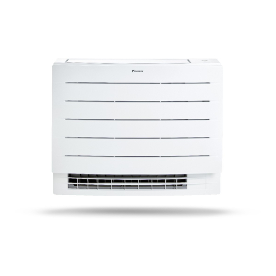
Daikin FVXM25A2V1B Installation Manual
Hide thumbs
Also See for FVXM25A2V1B:
- Installer's reference manual (60 pages) ,
- User reference manual (60 pages) ,
- Operation manual (20 pages)
Summary of Contents for Daikin FVXM25A2V1B
-
Page 1: Table Of Contents
Installation manual Split system air conditioners CVXM20A2V1B CVXM20A3V1B FVXM25A2V1B FVXM35A2V1B FVXM50A2V1B FVXM25A3V1B Installation manual FVXM35A3V1B English Split system air conditioners FVXM50A3V1B... -
Page 2: Table Of Contents
To re-install the front grille .......... 11 Daikin website (publicly accessible). 8.2.3 To re-install the front panel ......... 11 ▪ The full set of latest technical data is available on the Daikin 9 Commissioning Business Portal (authentication required). To perform a test run..............12 9.1.1... -
Page 3: About The Box
3 About the box WARNING WARNING The appliance shall be stored in a room without ALWAYS use multicore cable for power supply cables. continuously operating ignition sources (example: open WARNING flames, an operating gas appliance or an operating electric heater). Use an all-pole disconnection type breaker with at least 3 ... -
Page 4: About The Unit
Installation site requirements of the indoor unit INFORMATION INFORMATION ▪ Daikin Industries Czech Republic s.r.o. declares that the radio equipment type inside of this unit is in The sound pressure level is less than 70 dBA. compliance with Directive 2014/53/EU. WARNING ▪... -
Page 5: To Remove The Front Grille
5 Unit installation 2 Open the front panel and remove the string. Screw Sensor securing plate Metal plate cover To remove the electrical wiring box cover 1 Open the terminal block. 2 Remove 1 screw from the electrical wiring box. 3 Unhook the 2 tabs on the electrical wiring box cover and remove it. - Page 6 5 Unit installation Floor-standing installation Wall-mounted installation (mm) (mm) 5‒1 Indoor unit installation drawing: Floor-standing installation 5‒2 Indoor unit installation drawing: Wall-mounted installation Front view Side view Front view Top view Side view Screw hole 6× Top view Left-back piping hole location Mounting plate Right-back piping hole location Screw hole 4×...
- Page 7 5 Unit installation Half-concealed installation Bottom frame Slit portion 14 Align the unit using the alignment symbol on the mounting plate: 375 mm from the alignment symbol to the each side (unit width 750 mm), 487 mm from the alignment symbol to the bottom of the unit. (mm) 15 Hook the unit on the mounting plate and secure the unit to the wall using 4 screws M4×25L (field supply).
-
Page 8: To Drill A Wall Hole
5 Unit installation 2 Remove an burrs along the cut section using a half round 5.3.2 To drill a wall hole needle file. CAUTION For walls containing a metal frame or a metal board, use a wall embedded pipe and wall cover in the feed-through hole to prevent possible heat, electrical shock, or fire. -
Page 9: Piping Installation
6 Piping installation Piping installation Preparing refrigerant piping 6.1.1 Refrigerant piping requirements NOTICE 1× The piping and other pressure-containing parts shall be suitable for refrigerant. Use phosphoric acid deoxidised seamless copper for refrigerant. INFORMATION Additional refrigerant charge is NOT allowed in case of combination of the outdoor unit 3MXM40N8 or 3MXM52N8 Drain pan with the indoor units CVXM-A and/or FVXM-A. -
Page 10: Connecting The Refrigerant Piping
7 Electrical installation Connecting the refrigerant piping WARNING Do NOT connect the power supply to the indoor unit. This DANGER: RISK OF BURNING/SCALDING could result in electrical shock or fire. WARNING 6.2.1 To connect the refrigerant piping to the ▪ Do NOT use locally purchased electrical parts inside indoor unit the product. -
Page 11: To Connect Optional Accessories (Wired User Interface, Central User Interface, Wireless Adapter, Etc.)
8 Finishing the indoor unit installation To connect optional accessories To close the indoor unit (wired user interface, central user 8.2.1 To close the electrical wiring box and interface, wireless adapter, etc.) close the terminal block 1 Remove the electrical wiring box cover. See "5.2 ... -
Page 12: Commissioning
▪ A subset of the latest technical data is available on the regional Intelligent eye sensor Daikin website (publicly accessible). IPM* Intelligent power module ▪ The full set of latest technical data is available on the Daikin K*R, KCR, KFR, KHuR, K*M Magnetic relay Business Portal (authentication required). Live... - Page 13 11 Technical data Symbol Meaning Coil Reactor Stepper motor Compressor motor Fan motor Drain pump motor Swing motor MR*, MRCW*, MRM*, MRN* Magnetic relay Neutral n=*, N=* Number of passes through ferrite core Pulse-amplitude modulation PCB* Printed circuit board Power module Switching power supply PTC* PTC thermistor...
- Page 16 3P477070-2M 2021.09 Verantwortung für Energie und Umwelt...


Need help?
Do you have a question about the FVXM25A2V1B and is the answer not in the manual?
Questions and answers