Advertisement
Quick Links
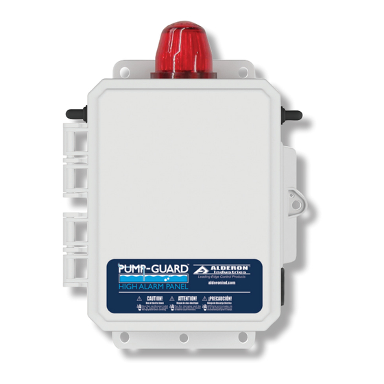
PUMP-GUARD
™
Single Phase, 120/240VAC | Type 4X Enclosure
Models: PG120 and PG240
QUICK START GUIDE
Step 2: Wiring | Float Switches
Wire the sensors (signaling device) to the terminal blocks listed below and
shown in the diagram for pump stop, pump start, and high level alarm.
FS1-Stop/Start Float; Wire #1
FS1-Stop/Start Float; Wire #2
FS2-High Level Float; Wire #1
FS2-High Level Float; Wire #2
(PG120 model shown, 120VAC)
1 2 3 4 T1 T2 L1 N
FS1
Stop/Start
Float
FS2
High Level
Float
High Alarm Panel
=
TB1:1
=
TB1:2
=
TB1:3
=
TB1:4
(TB1)
x x x x
Note: The PG high alarm panel
exact terminal block layout
may vary, but TB1:1, 2, 3, 4 is
consistent for wiring connections
Safety Guidelines
Before proceeding with the installation or operation of this product, read all instructions
thoroughly, as well as complying with all federal, state and local codes, regulations,
and practices. This product must be installed by qualified personnel familiar with all
applicable local electrical and mechanical codes. Refer to the National Electrical Code
(NEC) (NFPA 70). Failure to properly install, test, and operate this product can result in
personal injury or equipment malfunction.
1. DISCONNECT POWER when installing or servicing the product. Failure to disconnect
all power sources could result in serious injury or death.
2. NEVER enter a flooded space without proper Personal Protective Equipment (PPE).
Always wear dielectric rubber boots and other applicable protective equipment when
water is on the floor and you must service an energized pump, alarm system, or product.
3. DO NOT enter the water if the water level is higher than that of the protection your PPE
offers or if your PPE is not watertight.
4. DO NOT use or install this product with or near flammable liquids.
5. DO NOT use or install this product in locations classified as hazardous or in explosive
atmospheres as defined by any applicable electrical safety code.
Step 1: Installation
Use this quick start guide as reference to match up each component included to the
correct terminals inside the sensor panel shown in each step.
1. Mount and secure the sensor panel in the desired location. Recommended to use
four (4) screws (not included) and wall mount anchors (not included) if necessary.
2. Install using the appropriate conduit connections. Make sure all conduits are sealed
and waterproof per local codes.
3. WARNING: Do not mix high and low voltage wires in the same conduit or junction
box, failure to do so will cause system failure. Follow NEC requirements pertaining
to separation of voltages if run in the same conduit.
4. Incoming alarm/control power must match the sensor panel voltage. Refer to
included electrical schematic for complete wiring and voltage information.
Step 3: Wiring | Pump
Wire the pump connections (load) to the motor contactor terminals listed
below and shown in the diagram.
Pump Connection-T1
= TB1:T1
Pump Connection-T2
= TB1:T2
Ground Pump Motor PE = GND1 (control panel ground lug)
(PG120 model shown, 120VAC)
1 2 3 4 T1 T2 L1 N
x x x x
T1
PUMP 1
PE
1~
T2
120VAC, 15A, 60 Hz (PG120 model)
120/230VAC, 15A, 60 Hz (PG240 model)
WARNING
(TB1)
x x
Advertisement

Summary of Contents for Alderon Industries PUMP-GUARD PG120
- Page 1 Safety Guidelines PUMP-GUARD High Alarm Panel ™ WARNING Single Phase, 120/240VAC | Type 4X Enclosure Models: PG120 and PG240 Before proceeding with the installation or operation of this product, read all instructions thoroughly, as well as complying with all federal, state and local codes, regulations, and practices.
- Page 2 Step 4: Wiring | Incoming Power (PG120) Step 5: Wiring | Incoming Power (PG240) Wire the incoming alarm and pump/control power to the terminals listed Wire the incoming alarm and pump/control power to the terminals listed below and shown in the diagram. below and shown in the diagram.


Need help?
Do you have a question about the PUMP-GUARD PG120 and is the answer not in the manual?
Questions and answers