Advertisement
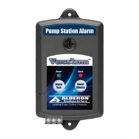
Versa'larm
1 Zone Alarm - Model VA01A
Operation, Maintenance and Installation Manual
Introduction
Before proceeding with the installation or operation of the Versa'larm™, read all instructions
thoroughly, as well as complying with all Federal, State and Local Codes, Regulations and
Practices. The Versa'larm must be installed by qualified personnel familiar with all applicable
local electrical and mechanical codes. Refer to the National Electrical Code (NFPA 70). Failure
to properly install and test this product can result in personal injury or equipment malfunction.
Power
Alarm
Silence
Alarm
Alarm
The Versa'larm is a multipurpose alarm that can be used in a wide variety of applications such as:
Test
Silence
septic tanks, sumps, holding tanks, pump chambers, water tanks, flow, pressure, condensate,
temperature and any other application where a "dry" contact can be connected to the Versa'larm.
These contacts can be connected to an Auto Dialer, a BAS (building automation system) or
SCADA system.
Safety Guidlines
1. DO NOT USE WITH FLAMMABLE OR EXPLOSIVE FLUIDS SUCH AS GASOLINE, FUEL OIL, KEROSENE,
ETC. DO NOT USE IN EXPLOSIVE ATMOSPHERES.
2. VERSA'LARM MUST BE MOUNTED INDOORS. FOR OUTDOOR APPLICATIONS CONSULT FACTORY.
Description of Operation
The Versa'larm is powered by 120 VAC coming from standard wall outlets and is transformed to 9-11 VDC.
Installing a 9 volt battery provides battery backup.
When a switch (signaling device) contact "closes" the buzzer and alarm light will turn "on" and the built in auxiliary
contacts will be activated. The signaling device could be a control duty float switch (e.g. Unimax™) or a water
sensor (e.g. WaterSpotter™, WaterSpotter™ Probe, Alderon Temperature Switch).
Pressing the "silence" switch deactivates the buzzer. When the alarm is remedied, the system automatically
resets itself.
Tools, Supplies and Requirements for Installation (Not Included)
1. Phillips screw driver
2. (Qty 2) #6 self tapping screws
3. Access to 120 VAC power receptacle
4. Optional - Plastic anchor if mounting to sheet rock
5. Optional - 9V battery (used for battery backup if power goes out)
6. Optional - Wire stripper (used if you need to strip wire to connect to a BAS or SCADA system)
7. Optional - Needle nose pliers if using auxiliary contacts
The Versa'larm is packaged as a stand alone item or with the specific sensor(s) you ordered it with. Other part
numbers and accesories are available. See catalog/website for more details. Examples below:
Power
Alarm
Power
Alarm
Silence
Silence
Alarm
Alarm
Alarm
Alarm
Test
Silence
Test
Silence
7013
7001
Alarm Systems
Control Panels
PO Box 827 Hawley, MN 56549 (218) 483-3034 Fax (218) 483-3036 www.alderonind.com
TM
Power
Alarm
Silence
Alarm
Alarm
Test
Silence
Unimax
Control
Float
7002
Float Switches
Power
Alarm
Power
Silence
Alarm
Alarm
Alarm
Test
Silence
Test
7003
Leak Detection Systems
P/N: 101444
Alarm
Power
Alarm
Silence
Silence
Alarm
Alarm
Alarm
Silence
Test
Silence
Unimax
Control
Float
7011
7151
Page 1 of 4
Advertisement
Table of Contents

Related Manuals for Alderon Industries Versa'larm VA01A


Summary of Contents for Alderon Industries Versa'larm VA01A
-
Page 1: Description Of Operation
Versa’larm 1 Zone Alarm - Model VA01A Operation, Maintenance and Installation Manual Introduction Before proceeding with the installation or operation of the Versa’larm™, read all instructions thoroughly, as well as complying with all Federal, State and Local Codes, Regulations and Practices. - Page 2 Versa’larm 1 Zone Alarm - Model VA01A Operation, Maintenance and Installation Manual Installation of the Versa’larm 1. To install/replace the battery for the backup power feature, remove the access cover (Fig. 1) and install 9 VDC battery (Duracell model MX 1604B2) (Fig. 2). After installing battery, press the test button (Fig. 3) to activate the alarm to make sure the battery works properly.
- Page 3 Versa’larm 1 Zone Alarm - Model VA01A Operation, Maintenance and Installation Manual Installation of the Versa’larm Continued 4. If connecting to existing alarm security system or BAS system leave Terminals “+” and “-” open and use 18 AWG 2 conductor wire to connect the existing product to Terminals 1A and 1B (Fig. 9). When connected, replace the access cover and pull the wires through the knockouts on the access cover (Fig.
- Page 4 Versa’larm 1 Zone Alarm - Model VA01A Operation, Maintenance and Installation Manual Installation of the Versa’larm Continued 7. Connect any combination of switches (rated 9 VDC, 200 mA MINIMUM) (Fig. 12) such as a float switch, pressure switch, WaterSpotter™, WaterSpotter™ Probe, etc. to Terminals C and 1 on the terminal block of the Caution! Versa’larm.
Need help?
Do you have a question about the Versa'larm VA01A and is the answer not in the manual?
Questions and answers