Advertisement
Quick Links
DURAPACK
HIGH-COMPACTION REAR LOADER
OPERATION MANUAL
ISSUED NOVEMBER 2024
© 2024 The Heil Co.
®
5000
WARNING
Failure to follow all instructions and safety precautions
in this manual, in the Service Manual, in other
manufacturers' manuals and on the safety decals
attached to the product could result in serious injury or
death to operators or bystanders and/or damage to
property.
DO NOT operate this vehicle before you READ and
UNDERSTAND this Operation Manual, the Service
Manual for this unit, other applicable manufacturers'
manuals, and the safety decals on the product.
Each operator of this unit must read and understand all
directions in this manual before they first operate this
vehicle.
Keep this manual in the cab for new operators and to
remind all operators about safe use.
TP1DP5-OM-1124
Advertisement

Subscribe to Our Youtube Channel
Related Manuals for HEIL DURAPACK 5000


Summary of Contents for HEIL DURAPACK 5000
- Page 1 Each operator of this unit must read and understand all OPERATION MANUAL directions in this manual before they first operate this ISSUED NOVEMBER 2024 vehicle. Keep this manual in the cab for new operators and to remind all operators about safe use. © 2024 The Heil Co. TP1DP5-OM-1124...
- Page 2 READ THIS MANUAL! EVERY PERSON who will OPERATE, MAINTAIN, REPAIR, OR OTHERWISE WORK with the Heil unit MUST READ AND UNDERSTAND this entire Operator’s Manual before starting the engine or activating any switches or controls. MAKE SURE to read the Service Manual for the unit BEFORE you do any maintenance or repair procedures.
- Page 3 ..............................33 Decals Decals ..............................36 Decal Placement ..............................37 Decal Images ..............................43 Reflective Safety Materials ..............................55 Care of Decals ..............................56 Lock-Out/Tag-Out Procedure Section Preview Section Preview ..............................60 Issued November 2024 Copyright 2024, The Heil Co. Table of Contents Printed in the U.S.A.
- Page 4 ..............................90 Factory Body Props / Propping the Tailgate Factory Body Props / Propping the Tailgate ..............................91 Propping the Tailgate (Continued) Propping the Tailgate (Continued) ..............................92 Issued November 2024 Copyright 2024, The Heil Co. Table of Contents Printed in the U.S.A.
- Page 5 Loading Refuse with a Winch ..............................128 Loading Refuse with a Winch (Continued) ..............................129 Loading Refuse with a Winch (Continued) ..............................130 Loading Refuse with a Winch (Continued) ..............................131 Issued November 2024 Copyright 2024, The Heil Co. Table of Contents Printed in the U.S.A.
- Page 6 End of Day Procedures Section Preview Section Preview ..............................156 Parking the Unit Parking the Unit ..............................157 Preventive Maintenance Chart Body Preventive Maintenance Chart Body Preventive Maintenance Chart ..............................160 Issued November 2024 Copyright 2024, The Heil Co. Table of Contents Printed in the U.S.A.
- Page 7 CNG Fuel System Inspections ..............................188 Inspection/Preventive Care Schedule / Preparation Before Maintenance ..............................189 Daily CNG Fuel System Inspection ..............................190 CNG Fuel System Troubleshooting CNG Fuel System Troubleshooting ..............................191 Issued November 2024 Copyright 2024, The Heil Co. Table of Contents Printed in the U.S.A.
- Page 8 ..............................194 CNG Fuel System Troubleshooting (Continued) ..............................195 Heil CNrG Solenoid System Option Heil CNrG Solenoid System Option ..............................196 Heil CNrG Solenoid System Option (Continued) ..............................197 Heil CNrG Solenoid System Option (Continued) ..............................198 Heil CNrG Solenoid System Option (Continued) ..............................199 Heil CNrG Solenoid System Option (Continued) ..............................200...
- Page 9 DURAPACK 5000 ® DURAPACK 5000 HIGH-COMPACTION REAR LOADER OPERATION MANUAL ISSUED NOVEMBER 2024 TP1DP5-OM-1124 Issued November 2024 Copyright 2024, The Heil Co. Printed in the U.S.A.
- Page 10 DURAPACK 5000 NOTES:...
- Page 11 DURAPACK 5000 SECTION 1 INTRODUCTION Issued November 2024 Copyright 2024, The Heil Co. Introduction Printed in the U.S.A.
- Page 12 Telephone numbers and website URL for parts, technical support, warranty claims, training and manuals Identifying the different models Identifying the left (street side) of the unit The unit serial plate Various parts of the unit Issued November 2024 Copyright 2024, The Heil Co. Introduction Printed in the U.S.A.
- Page 13 “All warranty repairs must be performed by …”. 10.End of Day Procedures 11.Preventive Maintenance Chart Each DANGER, WARNING, and CAUTION notice 12.Lubrication Guide precedes its applicable text. 13.Compressed Natural Gas (CNG) Options Issued November 2024 Copyright 2024, The Heil Co. Introduction Printed in the U.S.A.
- Page 14 This manual is designed to help ensure safe, efficient and the unit. proper operation of The Heil Co. d/b/a Heil Environmental You must make sure that repairs are made that may ("Heil") DuraPack 5000 Rear Loader refuse collection vehicle affect the safe operation of the unit before it is made (or the unit).
- Page 15 Refer to the Daily Checklist Manuals. Always read and understand all associated You must make sure that all decals and labels are manuals alongside the Heil Parts and Service Manual and clean and readable. Heil Operation Manual.
- Page 16 The owner or designated person can contact your Heil dealer or Heil for additional help. See Customer Service and Repair Parts Contact Information Issued November 2024 Copyright 2024, The Heil Co.
- Page 17 Repair or replace any failed or defective part immediately. You must receive proper training before you operate or service and maintain the unit. If you have not been trained, you must inform the owner. Issued November 2024 Copyright 2024, The Heil Co. Introduction Printed in the U.S.A.
- Page 18 WARRANTY CLAIMS AND INQUIRIES The HEIL ENVIRONMENTAL WARRANTY STATEMENT is printed on the inside, back cover of this manual. Should a failure occur that is covered by this warranty, contact the nearest Heil dealer for warranty repair unless otherwise authorized by Heil.
- Page 19 DURAPACK 5000 CONTACT INFORMATION Customer Care Phone: 866-275-4345 Technical Service Phone: 866-310-4345 Parts Central Phone: 800-528-5308 4301 Gault Avenue North Fort Payne, AL 35967 www.heil.com Issued November 2024 Copyright 2024, The Heil Co. Introduction Printed in the U.S.A.
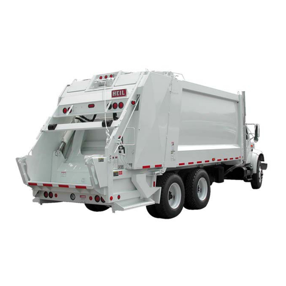
- Page 20 MODELS The DuraPack 5000 is a Rear End Loader (REL) and has one body model, the eject model. See the figure below. The sweep and upper panel open the hopper for loading refuse into the hopper, sweep the refuse into the body and compacts the refuse.
- Page 21 “curbside”. The figure below shows the locations of the serial plates on the street side of the unit’s body and tailgate. See the next page for a description of the information that is on the serial plate. Figure 2. Serial Plate Locations Issued November 2024 Copyright 2024, The Heil Co. Introduction Printed in the U.S.A.
- Page 22 Date of manufacture (last number of the year followed by the number of the day of the year, e.g. J078 is year 2018 and the 78th day of 2018). Issued November 2024 Copyright 2024, The Heil Co. Introduction Printed in the U.S.A.
- Page 23 The figure below shows the major components and their typical location on the unit. See the following pages for brief descriptions of each component shown below. Figure 4. Product Nomenclature (1 of 2) Issued November 2024 Copyright 2024, The Heil Co. Introduction Printed in the U.S.A.
- Page 24 The figure below shows the major components and their typical location on the unit. See the following pages for brief descriptions of each component shown below. Figure 5. Product Nomenclature (2 of 2) Issued November 2024 Copyright 2024, The Heil Co. Introduction Printed in the U.S.A.
- Page 25 Cart Tipper – One or more optional cart tippers can be located on the tailgate assembly. An operator uses a cart tipper to raise and dump a residential refuse container. The controls will be located on the rear, curb side of the unit. Issued November 2024 Copyright 2024, The Heil Co. Introduction Printed in the U.S.A.
- Page 26 RETRACT the ejector panel and CLOSE the tailgate. Front Head – The open area at the front of the body. You can see the ejector panel from the cab through the front head. Use Issued November 2024 Copyright 2024, The Heil Co. Introduction Printed in the U.S.A.
- Page 27 Operating the unit’s controls with a suspended load, such as a raised tailgate or a container on a lift mechanism, will allow the load to move even when the hydraulic pump is OFF. Issued November 2024 Copyright 2024, The Heil Co. Introduction Printed in the U.S.A.
- Page 28 This option allows an operator to load refuse from a commercial refuse container into the hopper. The controls will be located on the rear, curb side of the unit. Issued November 2024 Copyright 2024, The Heil Co. Introduction Printed in the U.S.A.
- Page 29 Slide (Upper Panel) Assembly – You move the slide assembly OUT while you move the packer panel UP to load refuse Issued November 2024 Copyright 2024, The Heil Co. Introduction Printed in the U.S.A.
- Page 30 Tailgate Cylinders – You use these cylinders to RAISE the tailgate before you unload the compacted refuse at the landfill. After you unload the refuse, you use the cylinders to LOWER the tailgate. Issued November 2024 Copyright 2024, The Heil Co. Introduction Printed in the U.S.A.
- Page 31 Winch Assembly – The winch assembly includes a winch, an attached cable with hook and controls. This option allows an operator to load refuse from a commercial refuse container into the hopper. The controls will be located on the rear, curb side of the unit. Issued November 2024 Copyright 2024, The Heil Co. Introduction Printed in the U.S.A.
- Page 32 (grab An attachment to the tailgate of a Rear End Loader (REL) that an operator grabs with their hands handles) while using the riding step. Issued November 2024 Copyright 2024, The Heil Co. Introduction Printed in the U.S.A.
- Page 33 Alerts you to practices not related to personal injury, such as damage to the unit or other NOTICE equipment off/OFF When a light is not illuminated / The position of a switch or other control to stop a function. Issued November 2024 Copyright 2024, The Heil Co. Introduction Printed in the U.S.A.
- Page 34 On Rear End Loaders (RELs), the platform at the side of the tailgate that an operator stands on while riding on the outside of the unit during collection activities Issued November 2024 Copyright 2024, The Heil Co. Introduction Printed in the U.S.A.
- Page 35 RPMs of the engine which results in greater flow of hydraulic fluid for operation of the tailgate, ejector and optional container lifting devices. unit The Heil DuraPack 5000 refuse collection vehicle referred to in this manual. UNLATCHED The side access door is not closed or secured.
- Page 36 DURAPACK 5000 NOTES:...
- Page 37 DURAPACK 5000 SECTION 2 SAFETY MESSAGES AND DECALS Issued November 2024 Copyright 2024, The Heil Co. Safety Messages and Decals Printed in the U.S.A.
- Page 38 General safety precautions and safety precautions for the safe operation and maintenance of the unit The safety precautions for NOT towing another vehicle or machine Safety decals on the unit Issued November 2024 Copyright 2024, The Heil Co. Safety Messages and Decals Printed in the U.S.A.
- Page 39 You must also read, understand and follow those messages. Issued November 2024 Copyright 2024, The Heil Co. Safety Messages and Decals Printed in the U.S.A.
- Page 40 PTO and PUSH the PUMP switch so it shuts or wear, REPLACE them IMMEDIATELY. Get decals off the pump. from your Heil dealer or Heil. o For units with automatic transmissions PUSH the DO NOT use this refuse collection vehicle to TOW SYSTEM POWER switch so the pump shuts off.
- Page 41 CHECK the height of the unit after you do any modifications to the chassis suspension. Any chassis suspension modification may change the height of the unit. See Tables 1 and 2. Issued November 2024 Copyright 2024, The Heil Co. Safety Messages and Decals Printed in the U.S.A.
- Page 42 Minimum Clearance 750 or less 4 feet (1.2 m) Above 750 to 50,000 6 feet (1.8 m) Above 50,000 to 345,000 10 feet (3 m) Issued November 2024 Copyright 2024, The Heil Co. Safety Messages and Decals Printed in the U.S.A.
- Page 43 ALL PERSONS MUST STAND CLEAR when the tailgate is in motion and during the unloading cycle. MAKE SURE no one stands under or crosses under a raised tailgate. TOWING OF ANY EQUIPMENT Heil DOES NOT recommend that you tow any kind of equipment with the unit. The unit was NOT DESIGNED nor intended for towing. Issued November 2024 Copyright 2024, The Heil Co.
- Page 44 Decal part numbers can be found below and in the Parts Manual. You can purchase replacement decals from your Heil Dealer or from the Heil Parts Central, 800-528- 5308.
- Page 45 DURAPACK 5000 DECAL PLACEMENT Issued November 2024 Copyright 2024, The Heil Co. Safety Messages and Decals Printed in the U.S.A.
- Page 46 DURAPACK 5000 DECAL PLACEMENT (CONTINUED) Issued November 2024 Copyright 2024, The Heil Co. Safety Messages and Decals Printed in the U.S.A.
- Page 47 DURAPACK 5000 DECAL PLACEMENT (CONTINUED) Issued November 2024 Copyright 2024, The Heil Co. Safety Messages and Decals Printed in the U.S.A.
- Page 48 DURAPACK 5000 DECAL PLACEMENT (CONTINUED) Issued November 2024 Copyright 2024, The Heil Co. Safety Messages and Decals Printed in the U.S.A.
- Page 49 DECAL, Danger, Access Door Closed ..........- ......1 212-1780 DECAL, Caution, Side Door ............- ......1 212-1915 DECAL, Information-Heil Replacement Parts ........- ......1 212-1909 DECAL, Warning, Overall Height ............. - ......1 212-1918 DECAL, Safety Instructions, Back-Up Alarm ........- ......1 Issued November 2024 Copyright 2024, The Heil Co.
- Page 50 DECAL, Caution, Disengage PTO ........... - ......1 212-1970 DECAL, Tailgate Raise Alarm ............- ......1 212-3551 DECAL, Preparing Unit to check Hydraulic Oil Level ......- ......1 Issued November 2024 Copyright 2024, The Heil Co. Safety Messages and Decals Printed in the U.S.A.
- Page 51 DURAPACK 5000 DECAL IMAGES Figure 7. Danger: Stand clear tailgate, PN 212-1801 Figure 6. Warning: Control Lever Operation, PN 212-1541 Issued November 2024 Copyright 2024, The Heil Co. Safety Messages and Decals Printed in the U.S.A.
- Page 52 Figure 9. Warning: Operations manual, PN 212-1783 Figure 10. Danger: Do not enter under, PN 212-1764 Figure 11. Danger: Stand clear packer, PN 212-1802 Issued November 2024 Copyright 2024, The Heil Co. Safety Messages and Decals Printed in the U.S.A.
- Page 53 Figure 12. Caution: Riding Step Speed panel, PN 212-1911 Limit, PN 212-1905 Figure 14. Hydraulic Oil Only, PN 212-1782 Figure 15. Danger: Not for towing, PN 212-1821 Issued November 2024 Copyright 2024, The Heil Co. Safety Messages and Decals Printed in the U.S.A.
- Page 54 Figure 17. Danger: Stay clear container, PN 212-1899 Figure 16. Warning: Do not Figure 18. Danger: Keep access door cross/stand behind, PN closed, PN 212-1907 212-2691 Issued November 2024 Copyright 2024, The Heil Co. Safety Messages and Decals Printed in the U.S.A.
- Page 55 Figure 19. Caution: Side access door only, PN 212-1780 Overall height, PN 212-1909 Figure 21. Buzzer, PN 212-1903 Figure 22. Caution: Disengage P.T.O., PN 212-1968 Issued November 2024 Copyright 2024, The Heil Co. Safety Messages and Decals Printed in the U.S.A.
- Page 56 Figure 23. Safety Requirements, ANSI, PN 212-1841 Figure 24. Throttle Advance, ANSI, PN 212-1904 Figure 26. Sweep/Slide Controls, PN 212-1969 Figure 25. Tailgate/Ejector Operation, PN 212-1906 Issued November 2024 Copyright 2024, The Heil Co. Safety Messages and Decals Printed in the U.S.A.
- Page 57 DURAPACK 5000 DECAL IMAGES (CONTINUED) Figure 27. Caution, Riding Step, ANSI, PN 212-1902 Figure 28. Flag, Made in USA, PN 212-2689 Issued November 2024 Copyright 2024, The Heil Co. Safety Messages and Decals Printed in the U.S.A.
- Page 58 DURAPACK 5000 Figure 29. Oil Level, PN Figure 30. Container Dump 212-2275 Mechanism Controls, PN 212-1838 Issued November 2024 Copyright 2024, The Heil Co. Safety Messages and Decals Printed in the U.S.A.
- Page 59 Figure 32. Heil Mechanism Controls, Replacement Parts, PN PN 212-1839 212-1915 Figure 34. Tailgate Raise Alarm, PN 212-1970 Figure 33. Safety Instructions, Back-Up Alarm, PN 212-1918 Issued November 2024 Copyright 2024, The Heil Co. Safety Messages and Decals Printed in the U.S.A.
- Page 60 DURAPACK 5000 DECAL IMAGES (CONTINUED) Figure 35. Caution: Tailgate Prop Operation, PN 212-2791 Issued November 2024 Copyright 2024, The Heil Co. Safety Messages and Decals Printed in the U.S.A.
- Page 61 DURAPACK 5000 DECAL IMAGES (CONTINUED) Figure 36. Lubrication Guide, PN 212-1542 Issued November 2024 Copyright 2024, The Heil Co. Safety Messages and Decals Printed in the U.S.A.
- Page 62 DECAL IMAGES (CONTINUED) Figure 38. City Logo, PN 212-2443 Figure 37. Hydraulic Oil Only, PN 212-2567 40. Sump Door, PN 212-2067 39. Stand Clear, PN 212-1911 Issued November 2024 Copyright 2024, The Heil Co. Safety Messages and Decals Printed in the U.S.A.
- Page 63 When you replace a part that had safety material on it, make sure you install new safety material on the new replacement part. See the Parts and Service Manual for all part numbers and location of the safety materials. You can purchase replacement decals from your Heil Dealer or from the Heil Parts Central, 800-528-5308. Issued November 2024 Copyright 2024, The Heil Co.
- Page 64 Do not use sharp angles to clean the decals – this can lift the decals from the unit. o NEVER use a “turbo pressure nozzle”. Issued November 2024 Copyright 2024, The Heil Co. Safety Messages and Decals Printed in the U.S.A.
- Page 65 DURAPACK 5000 PRESSURE WASHER TECHNIQUE Figure 41. Recommended Technique Figure 42. Incorrect Technique Issued November 2024 Copyright 2024, The Heil Co. Safety Messages and Decals Printed in the U.S.A.
- Page 66 Flush eyes and skin with water for 15 minutes after contact. Seek immediate medical help. Spot clean the decal with Isopropyl Alcohol and a micro-fiber cloth (rag). If these methods do not work on a problem area, call a Heil Dealer or Heil Customer Service. Issued November 2024 Copyright 2024, The Heil Co.
- Page 67 DURAPACK 5000 SECTION 3 LOCK-OUT/TAG-OUT PROCEDURE Issued November 2024 Copyright 2024, The Heil Co. Lock-Out/Tag-Out Procedure Printed in the U.S.A.
- Page 68 Read this section to learn about the proper Lockout/Tagout procedures. You MUST Lockout/Tagout a unit BEFORE: You enter the body Do any maintenance or repair procedures. Issued November 2024 Copyright 2024, The Heil Co. Lock-Out/Tag-Out Procedure Printed in the U.S.A.
- Page 69 DURAPACK 5000 LOCKOUT/TAGOUT PROCEDURE Watch the Service Shack Video online at www.Heil.com/ Heil-Service-Shack by selecting Lock-Out/Tag-Out. DANGER A. Put the unit in a Lockout/Tagout mode: This procedure MUST be followed before entering the units body or performing any maintenance repair or cleaning BEFORE you enter the unit’s body...
- Page 70 MUST place their personally assigned tag and lock 4. SET the body props when the body is raised for any to the multi-hasp connected to the disconnect service, maintenance or cleaning. switch. Issued November 2024 Copyright 2024, The Heil Co. Lock-Out/Tag-Out Procedure Printed in the U.S.A.
- Page 71 ENSURE all employees are safely positioned or removed from the area. d. NOTIFY all affected employees that the Lockout/ Tagout devices are being removed. Issued November 2024 Copyright 2024, The Heil Co. Lock-Out/Tag-Out Procedure Printed in the U.S.A.
- Page 72 DURAPACK 5000 NOTES:...
- Page 73 DURAPACK 5000 SECTION 4 IN-CAB DISPLAY AND CONTROLS Issued November 2024 Copyright 2024, The Heil Co. In-Cab Display and Controls Printed in the U.S.A.
- Page 74 The unit's features and operation specifications The in-cab display, controls, switches and buttons The in-cab display messages The outside controls and how they work Issued November 2024 Copyright 2024, The Heil Co. In-Cab Display and Controls Printed in the U.S.A.
- Page 75 12. Controller Faults Screen based on option configuration. 13. Password Protected Screens 14. Option Config Screen 15. Maintenance Screen Issued November 2024 Copyright 2024, The Heil Co. In-Cab Display and Controls Printed in the U.S.A.
- Page 76 Use the image below to identify the locations of the display indicators, function buttons, directional arrow buttons, "esc" and "ok" buttons, message banner, and status LED. Issued November 2024 Copyright 2024, The Heil Co. In-Cab Display and Controls Printed in the U.S.A.
- Page 77 Auto Work Lt – turns on body Work Light #1, tailgate hopper and tailgate side lights with System Enable and Vehicle Speed below 20MPH. Issued November 2024 Copyright 2024, The Heil Co. In-Cab Display and Controls Printed in the U.S.A.
- Page 78 8. Unused - Unused Indicators will be blank. 3. Filter Bypass GREEN, “FILTER OK” –- Return Filter is NOT in bypass. RED, “FILTER BYPASS” – Return Filter is in bypass. Issued November 2024 Copyright 2024, The Heil Co. In-Cab Display and Controls Printed in the U.S.A.
- Page 79 Error open circuit 12. Fault Indicator RED, “CRITIC FAULT” – Critical Fault RED, “CTRL. FAULT” – Controller Fault RED, “SYS. FAULT” – System Fault Issued November 2024 Copyright 2024, The Heil Co. In-Cab Display and Controls Printed in the U.S.A.
- Page 80 6. “Pump Shutdown Pressed, Reset Curbside Switch Restart System Enable.” Optional Pump Shutdown Refer to the Heil DuraPack 5000 Service Manual for a full System. To override and continue operation, enter list of possible faults along with each cause, effect, and Service Mode.
- Page 81 3. Hydraulic Filter Life – remaining filter life is below 5%. (BLACK BANNER) “Hyd. Oil Filter Life @: ##%” Hydraulic filter should be changed every 1000 pump hours. Issued November 2024 Copyright 2024, The Heil Co. In-Cab Display and Controls Printed in the U.S.A.
- Page 82 3. Hyd. Oil Life displays remaining life if the hydraulic oil based upon 2000 hours of pump operation. C.Other 1. Oil Temp High records the highest hydraulic oil temperature since reset. Issued November 2024 Copyright 2024, The Heil Co. In-Cab Display and Controls Printed in the U.S.A.
- Page 83 Additional screens allow a qualified and authorized Service Technician to see detailed system information and make configuration changes based on option configuration. Refer to the Heil DuraPack 5000 Service Manual for more information on these screens. 1. Display Screen 2. Cab Controller Inputs Screen 3.
- Page 84 MOVE and COMPACT the refuse in the hopper to the UPPER PANEL lever. It is the lever closest to the end of the body. tailgate. See the figures on the next two pages. Issued November 2024 Copyright 2024, The Heil Co. In-Cab Display and Controls Printed in the U.S.A.
- Page 85 DURAPACK 5000 STANDARD OUTSIDE CONTROLS (CONTINUED) Figure 44. Blade Control Lever Issued November 2024 Copyright 2024, The Heil Co. In-Cab Display and Controls Printed in the U.S.A.
- Page 86 DURAPACK 5000 STANDARD OUTSIDE CONTROLS (CONTINUED) Figure 45. Upper Panel Control Lever Issued November 2024 Copyright 2024, The Heil Co. In-Cab Display and Controls Printed in the U.S.A.
- Page 87 DURAPACK 5000 STANDARD OUTSIDE CONTROLS (CONTINUED) Figure 46. Normal Loading Cycle Issued November 2024 Copyright 2024, The Heil Co. In-Cab Display and Controls Printed in the U.S.A.
- Page 88 3. RELEASE the lever to stop an EXTEND or a RETRACT operation at any time or when the ejector panel is fully EXTENDED or RETRACTED. Issued November 2024 Copyright 2024, The Heil Co. In-Cab Display and Controls Printed in the U.S.A.
- Page 89 This means that you observe the safety message for using the riding step. Figure 47. Front Street Side Controls Figure 48. Buzzer Switch Location Issued November 2024 Copyright 2024, The Heil Co. In-Cab Display and Controls Printed in the U.S.A.
- Page 90 If equipped, use this switch to turn on the Hopper Light. See the figure to the right. Figure 49. Buzzer and Hopper Light Switch Location Issued November 2024 Copyright 2024, The Heil Co. In-Cab Display and Controls Printed in the U.S.A.
- Page 91 The increased flow of Figure 51. Optional Container Lift hydraulic oil increases the speed of the optional lifting Controls (2 of 2) equipment. Issued November 2024 Copyright 2024, The Heil Co. In-Cab Display and Controls Printed in the U.S.A.
- Page 92 Issued November 2024 Copyright 2024, The Heil Co. In-Cab Display and Controls Printed in the U.S.A.
- Page 93 5. PULL/PUSH the lever to RAISE the container over the hopper lip, dump the refuse from the container and lower the container to the ground. Issued November 2024 Copyright 2024, The Heil Co. In-Cab Display and Controls Printed in the U.S.A.
- Page 94 6. When the refuse container is empty, PUSH and RELEASE the lever to LOWER the cart tipper. At the end of the LOWER cycle, the cart tipper will stop lowering. Issued November 2024 Copyright 2024, The Heil Co. In-Cab Display and Controls Printed in the U.S.A.
- Page 95 Figure 53. Latch Bar Assembly 4. A “bash bar” prevents the container from over-rotating into the hopper. Issued November 2024 Copyright 2024, The Heil Co. In-Cab Display and Controls Printed in the U.S.A.
- Page 96 DURAPACK 5000 NOTES:...
- Page 97 DURAPACK 5000 SECTION 5 BODY AND TAILGATE PROPS Issued November 2024 Copyright 2024, The Heil Co. Body and Tailgate Props Printed in the U.S.A.
- Page 98 DURAPACK 5000 PREVIEW Read this section to learn about: Using the body props Using the tailgate props Issued November 2024 Copyright 2024, The Heil Co. Body and Tailgate Props Printed in the U.S.A.
- Page 99 Figure 54. Tailgate Clamps (Turnbuckles) Issued November 2024 Copyright 2024, The Heil Co. Body and Tailgate Props Printed in the U.S.A.
- Page 100 DURAPACK 5000 Issued November 2024 Copyright 2024, The Heil Co. Body and Tailgate Props Printed in the U.S.A.
- Page 101 DURAPACK 5000 SECTION 6 DAILY CHECKLIST Issued November 2024 Copyright 2024, The Heil Co. Daily Checklist Printed in the U.S.A.
- Page 102 Install new fiber guard on new hoses Worn or damaged tailgate lock components Replace worn or damaged components Loose or missing tailgate lock hardware Tighten loose hardware Replace missing hardware Issued November 2024 Copyright 2024, The Heil Co. Daily Checklist Printed in the U.S.A.
- Page 103 Body mounting brackets have loose hardware, Tighten loose hardware damaged hardware or cracked welds Replace missing hardware Repair cracked welds Air regulator (typically located at front of body) 90 PSI Issued November 2024 Copyright 2024, The Heil Co. Daily Checklist Printed in the U.S.A.
- Page 104 Refer to Preventative Maintenance Chart Signature of Operator: Lubrication Guide additional information and requirements. ________________________________________________________ Issued November 2024 Copyright 2024, The Heil Co. Daily Checklist Printed in the U.S.A.
- Page 105 Inspect all decals on cab for damage and readability. Inspect unit for refuse on or about the engine or exhaust components. Remove all refuse to prevent a fire. BODY AND CHASSIS CURB SIDE INSPECTION Issued November 2024 Copyright 2024, The Heil Co. Daily Checklist Printed in the U.S.A.
- Page 106 Cylinder for damage Loose or missing mounting hardware Inspect tailgate lock components Clamp components for wear and damage Loose or missing mounting hardware Make sure tailgate is locked Issued November 2024 Copyright 2024, The Heil Co. Daily Checklist Printed in the U.S.A.
- Page 107 Hoses for wear and damage Cylinder for damage Loose or missing mounting hardware for hydraulics Loose or missing hardware for packer panel BODY AND CHASSIS STREET SIDE INSPECTION Issued November 2024 Copyright 2024, The Heil Co. Daily Checklist Printed in the U.S.A.
- Page 108 Inspect body mounting brackets for cracked weld, missing bolts or nuts or movement. Inspect level of hydraulic oil if tank is mounted on street side. It must be full. Add recommended oil as necessary. Issued November 2024 Copyright 2024, The Heil Co. Daily Checklist Printed in the U.S.A.
- Page 109 Make sure all people not necessary and any hazards are clear of the area and then: Operate the in-cab controls and make sure: If equipped, engage the PTO Issued November 2024 Copyright 2024, The Heil Co. Daily Checklist Printed in the U.S.A.
- Page 110 The slide should move OUT Operate each installed optional outside control located at the tailgate: Reeving Mechanism Release the cable hook from it storage eye and hold the hook Issued November 2024 Copyright 2024, The Heil Co. Daily Checklist Printed in the U.S.A.
- Page 111 PUSH the control lever – the roll bar should LOWER Make sure the roll bar is at the full LOWER position Cart Tipper PULL the control lever – the cart tipper should RAISE Issued November 2024 Copyright 2024, The Heil Co. Daily Checklist Printed in the U.S.A.
- Page 112 RED TAILGATE OPEN (TG OPEN) in-cab display indicator is OFF and the alarm is OFF; GREEN TAILGATE CLOSED (TG CLOSED) display indicator is ON Keep the engine running and continue the inspection Issued November 2024 Copyright 2024, The Heil Co. Daily Checklist Printed in the U.S.A.
- Page 113 FINAL INSPECTION While you walk completely around the vehicle, look for: Fluid Leaks Cracked or damaged welds and metal Loose or missing bolts, nuts and clamps Issued November 2024 Copyright 2024, The Heil Co. Daily Checklist Printed in the U.S.A.
- Page 114 DURAPACK 5000 NOTES:...
- Page 115 DURAPACK 5000 SECTION 7 BEFORE GOING ON ROUTE Issued November 2024 Copyright 2024, The Heil Co. Before Going on Route Printed in the U.S.A.
- Page 116 Starting the unit in cold weather Setting the unit up for the route Removing power to the unit during periods of not using the unit Issued November 2024 Copyright 2024, The Heil Co. Before Going on Route Printed in the U.S.A.
- Page 117 Cable insulation must be free of damage and abrasion. Inspect weekly. NOTICE Always disconnect the battery before welding on the chassis or body. Issued November 2024 Copyright 2024, The Heil Co. Before Going on Route Printed in the U.S.A.
- Page 118 6. Make sure the oil temperature on the site gauge is between 120° and 160°F. If not, repeat step 5. 7. Check for fluid leaks. Repair if necessary. Issued November 2024 Copyright 2024, The Heil Co. Before Going on Route Printed in the U.S.A.
- Page 119 HYDRAULIC OIL LEVEL Current Heil standard hydraulic oil is Shell Tellus S2 VX Before checking the oil level or adding oil, make sure the oil 32. Please see product TDS and MSDS for more detail is warmed up and the unit is in the following position with all information about it.
- Page 120 DURAPACK 5000 HYDRAULIC OIL TANK WITH SIGHT GAUGE Figure 55. Hydraulic Oil Tank with Sight Gauge Issued November 2024 Copyright 2024, The Heil Co. Before Going on Route Printed in the U.S.A.
- Page 121 UNLOCK and RAISE the tailgate, then do at least one EJECTOR PANEL cycle, which includes a full EXTEND cycle and a full RETRACT cycle. Issued November 2024 Copyright 2024, The Heil Co. Before Going on Route Printed in the U.S.A.
- Page 122 For each door: o The quick release pin is secured in the barrel. o The wing screw is securely tightened against the door. Issued November 2024 Copyright 2024, The Heil Co. Before Going on Route Printed in the U.S.A.
- Page 123 DURAPACK 5000 CHECK THE TRAVELING OR “IN-TRANSIT” NOTES: POSITION (CONTINUED) Figure 57. In-Transit Position (Door Details) Issued November 2024 Copyright 2024, The Heil Co. Before Going on Route Printed in the U.S.A.
- Page 124 DURAPACK 5000 NOTES:...
- Page 125 DURAPACK 5000 SECTION 8 ON-ROUTE OPERATION PROCEDURES Issued November 2024 Copyright 2024, The Heil Co. On-Route Operation Procedures Printed in the U.S.A.
- Page 126 Setting up the unit for a route Loading refuse Packing the load Packing on-the-move Washout system Setting up the unit for the landfill or transfer station Issued November 2024 Copyright 2024, The Heil Co. On-Route Operation Procedures Printed in the U.S.A.
- Page 127 DO NOT use this station during travel to or from a route, landfill or transfer station. Issued November 2024 Copyright 2024, The Heil Co. On-Route Operation Procedures Printed in the U.S.A.
- Page 128 3. The packing mechanism should be in the START POSITION with the upper panel fully IN and the blade fully DOWN. See the figure 58. Issued November 2024 Copyright 2024, The Heil Co. On-Route Operation Procedures Printed in the U.S.A.
- Page 129 The hopper is now ready to receive refuse. 2. Load the refuse from a container into the hopper and then move the container to the pick-up location. Figure 59. Loading Refuse Issued November 2024 Copyright 2024, The Heil Co. On-Route Operation Procedures Printed in the U.S.A.
- Page 130 6. Repeat Steps 1 and 5 as necessary to compact the refuse. 7. Leave the blade against the refuse. 8. Move the refuse container to its pick-up location. Issued November 2024 Copyright 2024, The Heil Co. On-Route Operation Procedures Printed in the U.S.A.
- Page 131 PUSH the upper panel and blade levers at the same time and RELEASE the levers. The levers will self-center at the end of the commanded position by way of valve internal hydraulic pressure. Issued November 2024 Copyright 2024, The Heil Co. On-Route Operation Procedures Printed in the U.S.A.
- Page 132 Make sure the latch bar secures the container until the cable tightens and secures the hook in BEFORE you raise the container. See Using a the eye on the tailgate. Latch Bar Issued November 2024 Copyright 2024, The Heil Co. On-Route Operation Procedures Printed in the U.S.A.
- Page 133 See Using a Latch Bar i. MOVE the container to its pick-up location. Figure 61. Reeving Mechanism or Winch Setup Figure 62. Loading Refuse with Reeving Mechanism or Winch Issued November 2024 Copyright 2024, The Heil Co. On-Route Operation Procedures Printed in the U.S.A.
- Page 134 UP. STOP the blade UP operation when the blade is at the pinch point with the hopper sill. c. Watch for refuse that is pushed out of the hopper. Issued November 2024 Copyright 2024, The Heil Co. On-Route Operation Procedures Printed in the U.S.A.
- Page 135 5. Leave the blade against the refuse. ready to move to the next location. 7. Go to the next stop on the route. Issued November 2024 Copyright 2024, The Heil Co. On-Route Operation Procedures Printed in the U.S.A.
- Page 136 Stand clear of the packer panel and to the side of the hopper when operating packing mechanism. Issued November 2024 Copyright 2024, The Heil Co. On-Route Operation Procedures Printed in the U.S.A.
- Page 137 (2) Lower the container to the ground (3) Perform Step 3 (sweep the refuse and compact it into the hopper) (4) Raise the container and finish emptying the container. Issued November 2024 Copyright 2024, The Heil Co. On-Route Operation Procedures Printed in the U.S.A.
- Page 138 RELEASE the levers. The levers will self- center at the end of the commanded position by way of valve internal hydraulic pressure. See Figure 44 Issued November 2024 Copyright 2024, The Heil Co. On-Route Operation Procedures Printed in the U.S.A.
- Page 139 8. Go to the next stop on the route. Issued November 2024 Copyright 2024, The Heil Co. On-Route Operation Procedures Printed in the U.S.A.
- Page 140 The upper panel will move IN and the blade will move DOWN. (4) RAISE the container and finish emptying the container. c. The hopper is now ready to receive refuse. Issued November 2024 Copyright 2024, The Heil Co. On-Route Operation Procedures Printed in the U.S.A.
- Page 141 MOVE the container to its pick-up location. Figure 64. Arm Mechanism Setup Figure 65. Loading Refuse with Arm Mechanism Issued November 2024 Copyright 2024, The Heil Co. On-Route Operation Procedures Printed in the U.S.A.
- Page 142 Figure 66. Loading Refuse with Arm Mechanism move UP. STOP the blade UP operation when the blade is at the pinch point with the hopper sill. Issued November 2024 Copyright 2024, The Heil Co. On-Route Operation Procedures Printed in the U.S.A.
- Page 143 Do not use an arm mechanism or roll bar as a riding step. Obey safety messages and use the riding step for when traveling on the unit. Serious injury or death may occur. Issued November 2024 Copyright 2024, The Heil Co. On-Route Operation Procedures Printed in the U.S.A.
- Page 144 The hopper is now ready to receive refuse. bar before you raise or lower the container. Issued November 2024 Copyright 2024, The Heil Co. On-Route Operation Procedures Printed in the U.S.A.
- Page 145 RELEASE the container’s trunnion bar from the latch bar. See Using a Latch Bar g. RELEASE the container from the roll bar mechanism. Issued November 2024 Copyright 2024, The Heil Co. On-Route Operation Procedures Printed in the U.S.A.
- Page 146 DURAPACK 5000 LOADING REFUSE WITH A ROLL BAR MECHANISM (CONTINUED) Figure 67. Roll Bar Setup Figure 68. Loading Refuse with Roll Bar Issued November 2024 Copyright 2024, The Heil Co. On-Route Operation Procedures Printed in the U.S.A.
- Page 147 7. Go to the next stop on the route. Figure 69. Loading Refuse with a Roll Bar Issued November 2024 Copyright 2024, The Heil Co. On-Route Operation Procedures Printed in the U.S.A.
- Page 148 The upper panel will move IN and the sweep will move DOWN. c. The hopper is now ready to receive refuse. Issued November 2024 Copyright 2024, The Heil Co. On-Route Operation Procedures Printed in the U.S.A.
- Page 149 Clear the area near the hopper of all unnecessary people before you move the sweep and upper panel and keep all parts of your body away from the sweep. Issued November 2024 Copyright 2024, The Heil Co. On-Route Operation Procedures Printed in the U.S.A.
- Page 150 Watch for refuse that is pushed out of the hopper. Figure 72. Loading Refuse with Cart Tipper Issued November 2024 Copyright 2024, The Heil Co. On-Route Operation Procedures Printed in the U.S.A.
- Page 151 7. Go to the next stop on the route. container’s trunnion bar for lifting and lowering operations. See Figure 59 4. The bash bar prevents the container from over-rotating into the hopper. Issued November 2024 Copyright 2024, The Heil Co. On-Route Operation Procedures Printed in the U.S.A.
- Page 152 DURAPACK 5000 USING A LATCH BAR (CONTINUED) Figure 74. Latch Bars Rotated Up Figure 73. Latch Bars Rotated Down Issued November 2024 Copyright 2024, The Heil Co. On-Route Operation Procedures Printed in the U.S.A.
- Page 153 DURAPACK 5000 PACKING ON-THE-MOVE ACHIEVING PAYLOADS Heil DuraPack 5000 units can pack on-the move. The Read this section for advice and tips on how to pack operator does this manually while on the riding step (if the most efficient loads with your unit.
- Page 154 For each door: o The quick release pin is secured in the barrel. o The wing screw is securely tightened against the door. Issued November 2024 Copyright 2024, The Heil Co. On-Route Operation Procedures Printed in the U.S.A.
- Page 155 DURAPACK 5000 SECTION 9 LANDFILL/TRANSFER STATION/ RECYCLE CENTER PROCEDURES Issued November 2024 Copyright 2024, The Heil Co. Landfill/Transfer Station/Recycle Center Printed in the U.S.A. Procedures...
- Page 156 Read this section to learn about: Setup conditions to dump the refuse Unloading the refuse Using the sump and (optional) washout system Preparing the unit to return to route. Issued November 2024 Copyright 2024, The Heil Co. Landfill/Transfer Station/Recycle Center Printed in the U.S.A. Procedures...
- Page 157 Always stop the unit on the most stable, hard, dry and level surface you can find before you empty the refuse. Issued November 2024 Copyright 2024, The Heil Co. Landfill/Transfer Station/Recycle Center Printed in the U.S.A. Procedures...
- Page 158 Activate the pump activation switch until the ejector panel is fully RETRACTED and at the front of the body. b. RELEASE the eject lever. Figure 75. Tailgate Controls Issued November 2024 Copyright 2024, The Heil Co. Landfill/Transfer Station/Recycle Center Printed in the U.S.A. Procedures...
- Page 159 Inspect the seal for possible wear or damage and replace if necessary. Figure 76. Unloading Refuse Issued November 2024 Copyright 2024, The Heil Co. Landfill/Transfer Station/Recycle Center Printed in the U.S.A. Procedures...
- Page 160 NOTICE The TAILGATE OPEN warning light will go OFF and the alarm will stop when TAILGATE is FULLY locked. Figure 77. Lowering the Tailgate Issued November 2024 Copyright 2024, The Heil Co. Landfill/Transfer Station/Recycle Center Printed in the U.S.A. Procedures...
- Page 161 H. Sump Doors and Washout System 2. Replace tailgate pins. The DuraPack 5000 unit does not have sump doors. F. Clean and Inspect the Hopper and Packer Panel If equipped, use the optional washout system to clean out the body and hopper at the end of a work day.
- Page 162 You properly ADJUST and CLEAN the mirrors. All outside lights turn ON and OFF. If equipped, the side access door is CLOSED and LOCKED. Issued November 2024 Copyright 2024, The Heil Co. Landfill/Transfer Station/Recycle Center Printed in the U.S.A. Procedures...
- Page 163 DURAPACK 5000 SECTION 10 END OF DAY PROCEDURES Issued November 2024 Copyright 2024, The Heil Co. End of Day Procedures Printed in the U.S.A.
- Page 164 DURAPACK 5000 PREVIEW Read this section to learn about: Parking the Unit Final Inspection Report to Employer/Supervisor Ignition Keys Issued November 2024 Copyright 2024, The Heil Co. End of Day Procedures Printed in the U.S.A.
- Page 165 Put the ignition keys in a secure storage area designated by cylinders, valves, pump and fittings. Report any leaks your employer/supervisor. to your employer/supervisor. Issued November 2024 Copyright 2024, The Heil Co. End of Day Procedures Printed in the U.S.A.
- Page 166 DURAPACK 5000 NOTES:...
- Page 167 DURAPACK 5000 SECTION 11 PREVENTIVE MAINTENANCE CHART Issued November 2024 Copyright 2024, The Heil Co. Preventive Maintenance Chart Printed in the U.S.A.
- Page 168 Electrical, Battery Cables Check for proper operation. Check battery cables from battery to starter for loose cables, rubbing or damage and abrasions to cables. Replace if necessary. Issued November 2024 Copyright 2024, The Heil Co. Preventive Maintenance Chart Printed in the U.S.A.
- Page 169 Maintenance in Service Manual. * Daily = 8 hrs. Weekly = 40 hrs. Monthly = 200 hrs. 6 Months = 1000 hrs. Yearly = 2000 hrs. Issued November 2024 Copyright 2024, The Heil Co. Preventive Maintenance Chart Printed in the U.S.A.
- Page 170 DURAPACK 5000 NOTES:...
- Page 171 DURAPACK 5000 SECTION 12 LUBRICATION GUIDE Issued November 2024 Copyright 2024, The Heil Co. Lubrication Guide Printed in the U.S.A.
- Page 172 Clean fittings before applying grease and always pump enough grease into joint to remove the old grease. Wipe off excess grease. Lubricate movable mechanical parts without fittings every 60 days with non-detergent engine oil. Issued November 2024 Copyright 2024, The Heil Co. Lubrication Guide Printed in the U.S.A.
- Page 173 Container Mech. Control: A. Handle Weekly/40 Hours B. Upper Pivot Weekly/40 Hours Ejector Cylinder (Not Shown) Weekly/40 Hours Access Door Hinges (Not Shown) Every 60 Days Issued November 2024 Copyright 2024, The Heil Co. Lubrication Guide Printed in the U.S.A.
- Page 174 DURAPACK 5000 NOTES:...
- Page 175 DURAPACK 5000 SECTION 13 COMPRESSED NATURAL GAS (CNG) OPTION Issued November 2024 Copyright 2024, The Heil Co. Compressed Natural Gas (CNG) Option Printed in the U.S.A.
- Page 176 QUALIFIED, CONSULT YOUR ORGANIZATION’S EHS FUNCTION BEFORE USE OR PERFORMING ANY WORK. Please note that various procedures are different from other Heil bodies due to the CNG system – please read this Manual and related documents in full. This Manual does not substitute for proper training and certification.
- Page 177 CNG fuel storage system. DANGER Keep work area well ventilated. WARNING Do not start the engine if a natural gas leak is detected. Issued November 2024 Copyright 2024, The Heil Co. Compressed Natural Gas (CNG) Option Printed in the U.S.A.
- Page 178 Do not use a cell phone or other electronic device within 30 feet of a compressed natural gas vehicle or a dispensing/filling station. WARNING When replacing CNG components, replace with equal or higher pressure rated components. Issued November 2024 Copyright 2024, The Heil Co. Compressed Natural Gas (CNG) Option Printed in the U.S.A.
- Page 179 Do not use any other method or products to Lower Explosive Limit (%): 3.8 – 6.5 find leaks. Upper Explosive Limit (%): 13 – 17 Issued November 2024 Copyright 2024, The Heil Co. Compressed Natural Gas (CNG) Option Printed in the U.S.A.
- Page 180 Rotate the handle counterclockwise so arrow points up to the ‘ON’ position to allow fuel flow from the tanks to the vehicle’s engine. Issued November 2024 Copyright 2024, The Heil Co. Compressed Natural Gas (CNG) Option Printed in the U.S.A.
- Page 181 Prevent hoists or jacks from coming into direct contact with containers. B. Fuel Management Module Components (Continued) Figure 79. Manual Shut-Off Valve (Typical arrangement; models may vary slightly in component positioning.) Issued November 2024 Copyright 2024, The Heil Co. Compressed Natural Gas (CNG) Option Printed in the U.S.A.
- Page 182 "MANUAL SHUTOFF VALVE" that is adjacent to the cylinder. Turn the valve handle FULLY clockwise to close the valve or FULLY counter- clockwise to open it. Issued November 2024 Copyright 2024, The Heil Co. Compressed Natural Gas (CNG) Option Printed in the U.S.A.
- Page 183 Issued November 2024 Copyright 2024, The Heil Co. Compressed Natural Gas (CNG) Option Printed in the U.S.A.
- Page 184 Issued November 2024 Copyright 2024, The Heil Co. Compressed Natural Gas (CNG) Option Printed in the U.S.A.
- Page 185 2. Turn OFF Fuel Management Module Manual Shut-Off Valve. 3. Turn OFF the Fuel Cylinder Manual Shut-Off Valve on EACH tank. 4. Call Technical Services at 866-310-4345 for further assistance. Issued November 2024 Copyright 2024, The Heil Co. Compressed Natural Gas (CNG) Option Printed in the U.S.A.
- Page 186 For tailgate mounted CNG, vent lines route to WARNING the top of the tailgate. If the plastic caps are missing, contact Heil Parts Central for replacement caps at 800- BEFORE fueling the CNrG Solenoid System (if equipped), 528-5308.
- Page 187 This indicates that the nozzle fueling nozzle is properly seated onto the receptacle. Issued November 2024 Copyright 2024, The Heil Co. Compressed Natural Gas (CNG) Option Printed in the U.S.A.
- Page 188 Figure 81. Type 1 Fueling Nozzle 1. Type 1 (Continued): Figure 83. Type 2 Fueling Nozzle Figure 82. Type 1 Fueling Nozzle Issued November 2024 Copyright 2024, The Heil Co. Compressed Natural Gas (CNG) Option Printed in the U.S.A.
- Page 189 Rotate lever clockwise 180° to begin fueling. d. When fueling is complete, rotate lever counterclockwise 180° to allow fuel hose disconnection. Figure 84. Type 3 Fueling Hose Issued November 2024 Copyright 2024, The Heil Co. Compressed Natural Gas (CNG) Option Printed in the U.S.A.
- Page 190 CNG FUEL SYSTEM MAINTENANCE Routine maintenance of the compressed natural gas system in accordance with the CNG Fuel System Inspections Section will ensure that the system and components are functioning properly. Refer to your Heil Service Manual for CNG fuel system schematics. WARNING 1.
- Page 191 Parts Central Electronic Parts Catalog (EPC). Register online to gain access to the EPC: https://epc.partscentral.com Google Chrome web browser is recommended. Issued November 2024 Copyright 2024, The Heil Co. Compressed Natural Gas (CNG) Option Printed in the U.S.A.
- Page 192 Check for the presence of gas leaks before welding. Welding can ignite the fuel, resulting in an explosion or fire causing serious personal injury or death. Issued November 2024 Copyright 2024, The Heil Co. Compressed Natural Gas (CNG) Option Printed in the U.S.A.
- Page 193 8. Re-install the filter bowl in the filter housing and torque to 40 FT-LBS. 9. Follow the Repressurizing procedure in this manual for the system applicable on your truck Issued November 2024 Copyright 2024, The Heil Co. Compressed Natural Gas (CNG) Option Printed in the U.S.A.
- Page 194 CNG fuel system, you must perform the following procedures: 1. Conduct work in a well-ventilated area. 2. Perform defueling procedure as instructed in this manual. Issued November 2024 Copyright 2024, The Heil Co. Compressed Natural Gas (CNG) Option Printed in the U.S.A.
- Page 195 FMM and all fuel cylinders using the Fuel System Shut Down Procedure Once the fuel system is shut down, follow the vehicle manufacturer’s instructions for towing the vehicle. Issued November 2024 Copyright 2024, The Heil Co. Compressed Natural Gas (CNG) Option Printed in the U.S.A.
- Page 196 85-150 psi. 7. Verify the dashboard fuel gauge is functioning properly. Issued November 2024 Copyright 2024, The Heil Co. Compressed Natural Gas (CNG) Option Printed in the U.S.A.
- Page 197 Monthly Cylinders Inspect compressed gas cylinders as outlined by cylinder manufacturer NOTE: All inspections to be completed by a qualified and trained person. Issued November 2024 Copyright 2024, The Heil Co. Compressed Natural Gas (CNG) Option Printed in the U.S.A.
- Page 198 Gas leaks – Smell for gas, look for frost or ice and months by a qualified inspector. listen for hissing noises at joints and components. 2. In addition, Heil recommends a daily walk-around or pre- b. Pressure Relief Device (PRD) components – Make trip and post-trip visual inspection be performed.
- Page 199 CNG FUEL SYSTEM TROUBLESHOOTING Heil offers support via the technical assistance line to assist with troubleshooting. Please provide the following when calling Heil Technical Services at 866-310-4345 with troubleshooting questions: 1. Serial # of CNG Fuel Module 2. Truck Serial # 3.
- Page 200 If the problem cannot be (GRN) and 10 (YEL). resolved, call 866-310-4345 Continuity should be lost for technical assistance. when the switch is released. Issued November 2024 Copyright 2024, The Heil Co. Compressed Natural Gas (CNG) Option Printed in the U.S.A.
- Page 201 "Off" and "Run" resolved, call 866-310-4345 while listening for the "click" of for technical assistance. the fuel solenoid being actuated near the maintenance door. Issued November 2024 Copyright 2024, The Heil Co. Compressed Natural Gas (CNG) Option Printed in the U.S.A.
- Page 202 The problem is likely in the vehicle's wiring or the in-cab fuel gauge. *If the problem cannot be resolved, call 866-310-4345 for assistance. Issued November 2024 Copyright 2024, The Heil Co. Compressed Natural Gas (CNG) Option Printed in the U.S.A.
- Page 203 The problem is likely in the Display or the Controller. *If the problem cannot be resolved, call 866-310-4345 for assistance. Issued November 2024 Copyright 2024, The Heil Co. Compressed Natural Gas (CNG) Option Printed in the U.S.A.
- Page 204 Display screen inside the cab which gives live pressure monitoring for each tank and system. When equipped, the optional Heil CNrG Solenoid System Visual warning in form of messages and color on the will monitor and display live in-cab CNG system and tank...
- Page 205 DURAPACK 5000 HEIL CNrG SENTINEL SOLENOID SYSTEM OPTION (CONTINUED) Pressure Transducer Sensors WARNING ALL Pressure Transducer Sensors MUST be functioning for System to be able to detect a leak. WARNING Tank MUST be empty before removing tank Pressure Figure 88. Pressure Transducer Sensor.
- Page 206 OFF (ignition must be turned ON to see more details about the leak on the display screen). NOTICE Authorized Service Personnel should contact Heil Technical Service for the maintenance code to unlock the CNG solenoids. Figure 91. Alarm Summary...
- Page 207 DURAPACK 5000 HEIL CNrG SENTINEL SOLENOID SYSTEM OPTION (CONTINUED) Leak Detection/Solenoid Lock (Continued) The figures on this page show example display screenshots of possible leak detection notifications. Other leak detection notifications exist and are not shown here. WARNING You must follow all safety/emergency procedures of your company in the event of a CNG leak.
- Page 208 Other solenoid failure detection notifications exist and are not shown here. To defuel after a solenoid failure on one of the tanks, first refer to Heil CNrG Solenoid System Defueling After Solenoid Failure and then use one of the methods...
- Page 209 DURAPACK 5000 NOTICE HEIL CNrG SENTINEL SOLENOID SYSTEM OPTION (CONTINUED) Authorized Service Personnel should contact Heil Technical Service for the maintenance bypass code to unlock the Maintenance Bypass CNG solenoids. The following are the steps must be followed by a qualified maintenance technician after getting any display messages described in this manual.
- Page 210 DURAPACK 5000 CNG Tank Option Configuration HEIL CNrG SENTINEL SOLENOID SYSTEM OPTION (CONTINUED) The system is designed for different tank configurations and is a common design which will work from 3 tank to 7 tank Low Fuel Level Detection system. This helps the customer to upgrade to higher DGE...
- Page 211 DURAPACK 5000 System Outputs HEIL CNrG SENTINEL SOLENOID SYSTEM OPTION (CONTINUED) The display screenshot shown below (within the maintenance mode menu) is used for troubleshooting and System Inputs maintenance to gather information for the current status of the Solenoids on each Tank (ON or OFF). It also provides The display screenshot shown below (within the the status of the System Alarm for the Controller.
- Page 212 DURAPACK 5000 System Over Voltage HEIL CNrG SENTINEL SOLENOID SYSTEM OPTION (CONTINUED) The display notification shown in the figure below will only be displayed in the event that the System Voltage is greater Ignition Power OFF than 36 volts for 10 seconds, indicating that there is voltage too high to safely operate the Controller and Display.
- Page 213 Figure 104. Display Screenshot: System Under Voltage Figure 105. Display Screenshot: Figure 106. Display Screenshot: Fuel Fill Mode OFF Fuel Fill Mode ON Issued November 2024 Copyright 2024, The Heil Co. Compressed Natural Gas (CNG) Option Printed in the U.S.A.
- Page 214 DURAPACK 5000 NOTES:...
- Page 215 Issued November 2024 Copyright 2024, The Heil Co. Index Printed in the U.S.A.
- Page 216 37, 38, 39, 40, 41 pressure transducer sensors driving to pick-up locations solenoid failure detection system over voltage Heil CNrG SENTINEL solenoid system option ejector & tailgate controls defueling after solenoid failure ejector lever leak detection ejector panel leak detection/solenoid lock ejector panel &...
- Page 217 INDEX Heil CNrG SENTINEL solenoid system option system outputs system under voltage latch bar 17, 24 tank option configuration latch bar assembly hopper 17, 24 LATCHED hopper light switch leaving the route for the landfill/transfer station hopper sill LOAD POSITION...
- Page 218 76, 77, 78, 79, 80, 81, 82 product nomenclature 15, 16, 17 streetside vs. curbside propping the tailgate 91, 92 sump doors and washout system tailgate raise/RAISE Issued November 2024 Copyright 2024, The Heil Co. Index Printed in the U.S.A.
- Page 219 78, 79 upper panel lever use of curb side drive use personal protective equipment using a latch bar 143, 144 warming up the hydraulic oil warning 24, 31 Issued November 2024 Copyright 2024, The Heil Co. Index Printed in the U.S.A.
- Page 220 DURAPACK 5000 NOTES:...
- Page 221 ALTERATION OR REPAIR BY OTHERS IN SUCH A MANNER AS IN HEIL’S SOLE JUDGMENT AFFECTS THE PRODUCT OPERATION OR INTEGRITY SHALL VOID THE WARRANTY. Heil retains the right to modify its factory warranty program at any time. The warranty in place at the time of your respective purchase applies.
- Page 222 Custom er Care: 866-ASK-HEIL (866-275-4345) The Heil Co. 4301 Gault Avenue North Fort Payne, AL 35967-9984 Parts Central: 800-528-5308 Technical Service: 866-310-4345 TechSupport@DoverESG.com...
Need help?
Do you have a question about the DURAPACK 5000 and is the answer not in the manual?
Questions and answers