Advertisement
Available languages
Available languages
Quick Links
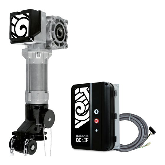
Kit
BBS100TKF
BBS100TKL
Motoriduttore per porte sezionali
Motoréducteur pour porte sectionnelle
Motor para puertas seccionales
Centrale di comando
Sectional door drive
Control unit
Armoire de commande
Central de mando
6
12
7
20
8
28
9
36
Made in Italy
Advertisement

Subscribe to Our Youtube Channel
Related Manuals for GAPOSA BBS


Summary of Contents for GAPOSA BBS
- Page 1 BBS100TKF BBS100TKL Motoriduttore per porte sezionali Centrale di comando Sectional door drive Control unit Motoréducteur pour porte sectionnelle Armoire de commande Motor para puertas seccionales Central de mando Made in Italy...
- Page 2 These motors have been developed according to the EEC standards EN 12453. BBS is carefully checked and is sold in total safety. In order to maintain this situation and to ensure safe operations, the user must comply with all the recommendations contained in the present instructions for use. In the general use, the electrical connections must be performed by qualified personnel, who must be able to judge the work to be done, to recognize the sources of danger and take appropriate safety measures.
- Page 3 Definitivamente usted debería tomar nota de estos consejos durante la instalación y el uso. • El montaje, la apertura de la caja de los finales de carrera y la conexión eléctrica del motor BBS deben hacerse con la tensión de alimentación cortada.
- Page 4 ALIMENTAZIONE - POWER SUPPLY - ALIMENTATION - ALIMENTACCIÓN (FIG. 1) FIG. 1 Comune Common Commun Común Terra Ground Terre Tierra Verso rotazione Direction of Sens de Sentido de rotation 1 rotation 1 rotación 1 Verso rotazione Direction of Sens de Sentido de rotation 2 rotation 2...
- Page 5 CAMBIO TENSIONE - VOLTAGE CHANGE - CHANGEMENT DE TENSION - CAMBIO DE VOLTAJE Escluso BHS100 3~ 400V Excluding BHS100 À l’exclusion de BHS100 Motore 50 Hz Excluyendo BHS100 Motor Moteur Motor Centralina Elettrofreno Control unit Electrobrake 230V~ Coffret Electrofrein Central de mando Electrofreno 3~ 230V Elettrofreno...
- Page 6 1. CONSIGLI PER L’INSTALLAZIONE Il BBS, per le sue dimensioni compatte, può essere installato anche laddove lo spazio disponibile è limitato. Se tale spazio non è co- munque sufficiente, a richiesta, è disponibile un kit d’installazione con rinvio a catena, che riduce l’ingombro laterale. La figura a pg.16 mostra le dimensioni di ingombro del motoriduttore e le quote di fissaggio della base.
- Page 7 220 mm between the middle of the shaft and the lintel. When fastening to the wall the bracket of the BBS to one side and the bracket of the bearing to the other one, always consider the differences in height between these two brackets to ensure that the rolling shaft is installed perfectly horizontal.
- Page 8 1. CONSEILS POUR L’INSTALLATION Le BBS, grâce à ses dimensions compactes, peut être installé dans les espaces réduits. À la demande, un kit d’installation pour le renvoi à chaîne est disponible, qui réduit encore plus l’encombrement latéral. L’illustration à la p. 16 montre les dimensions d’encom- brement du motoréducteur et les points de fixation du support.
- Page 9 Controlar que la tensión de red disponible en la instalación corresponde a la tensión para la cual está predispue- sto el BBS y que la línea tiene una sección adecuada y dispone de un conductor de tierra. La conexión eléctrica debe realizarse según lo que se indica en el párrafo “Tipos y ajuste de los finales de carrera”, en el momento que la conexión varia según el tipo...
- Page 11 Alimentazione / Potenza motore 3~400V ± 5% - 50/60 Hz / 1.0 kW Corrente massima Tensione e corrente max relè 30 VDC - 1 A ausiliari Condizione Carico 24V~ COM (12V ) Fusibile di protezione Caso 1 0 mA 140 mA 3x 4.0 A Grado di protezione IP54...
- Page 12 CONNESSIONI BBS100TKF BBS100TKL MOTORE CON ENCODER GRIGIO GIALLO SICUREZZE VERDE ROSA BIANCO MARRONE ATTENZIONE: é possibile abilitare solo un tipo di sicurezza QC40F QC40L COSTA 8K2 CAVO FLSI4P65.50 (NON INCLUSO) CONTATTO PORTA PEDONALE QCF4 RELE AUX1 RELE AUX2 COMUNE CONNESSIONE ENCODER 24 VAC 1 2 3 4 5 6 7 8 9 10...
- Page 13 1 MESSA IN FUNZIONE 1.1 SETTAGGIO DEL VERSO DI ROTAZIONE ATTENZIONE: Durante la definizione del verso le sicurezze non sono attive Non appena si alimenta il motore (o dopo il RESET) il LED rosso fisso e il LED verde in lampeggio veloce indicano la necessità...
- Page 14 2. PROGRAMMAZIONE 1 2 3 4 5 6 7 8 9 10 PROGRAMMAZIONE TRASMETTITORI (DIP1) MODALITÀ FUNZIONAMENTO (DIP 2 / 3) RILEVAMENTO OSTACOLO (DIP 4) SICUREZZE (DIP 5) CHIUSURA AUTOMATICA (DIP 7) PRE-FINECORSA (DIP 8) AUX1 / AUX 2 (DIP 9 / 10) 2.1 PROGRAMMAZIONE TRASMETTITORE (con modulo ricevente radio opzionale) Per associare ad un codice radio la funzione di START/STOP è...
- Page 15 La modalità di funzionamento viene selezionata tramite i DIP 2 e 3 secondo la seguente tabella: DIP2 DIP3 MODALITÀ Impulsiva (SALITA > STOP > DISCESA > STOP > SALITA > ...) Impulsiva APERTURA / Uomo-presente CHIUSURA Start/Stop Condominiale Uomo-presente APERTURA e CHIUSURA 2.4 LOGICA SICUREZZA La logica della sicurezza è...
- Page 16 > QC40L La selezione del dispositvo di sicurezza è gestita tramite il DIP5 DIP5 DISPOSITIVO DI SICUREZZA MORSETTI 14 - 15 Contatto NC NON COLLEGARE Sicurezza con segnale digitale (OSE/FSS) (massa su morsetto 22, +12VCC su morsetto 14, NON COLLEGARE segnale digitale su morsetto 16) ATTENZIONE! Il valore della tensione in uscita su COM può...
- Page 17 2.9 RELÉ AUSILIARI La scheda è dotata di due relè ausiliari (AUX1 ed AUX2) le cui funzioni sono programmabili tramite il DIP9 e il DIP10 DIP9 AUX1 Il relè si attiva al raggiungimento dello stato CHIUSO della serranda Il relè si attiva al raggiungimento dello stato APERTO della serranda DIP10 AUX2 Il relè...
- Page 18 WIRING BBS100TKF BBS100TKL ENCODER MOTOR GREY YELLOW SAFETIES GREEN PINK WHITE BROWN ATTENTION: it is possible to enable only one type of safety QC40F QC40L SAFETY EDGE 8K2 CABLE FLSI4P65.50 (NOT INCLUDED) CONTACT PEDESTRIAN DOOR QCF4 SAFETY BEAMS RELE AUX1 RELE AUX2 COMMON ENCODER...
- Page 19 1 COMMISSIONING 1.1SETTING THE DIRECTION OF ROTATION ATTENTION: When defining the direction, the safeties are not active. As soon as the motor is powered up (or after RESET), the steady red LED and the fast-flashing green LED indicate the need to set the direction of adjustment and then the adjustment of both limit switches: 1.
- Page 20 2. PROGRAMMING 1 2 3 4 5 6 7 8 9 10 PROGRAMMING TRANSMITTERS (DIP1) OPERATING MODES (DIP 2 / 3) OBSTACLE DETECTION (DIP 4) SAFETY (DIP 5) AUTOMATIC CLOSING (DIP 7) PRE-LIMIT SWITCH (DIP 8) AUX1 / AUX 2 (DIP 9 / 10) 2.1 TRANSMITTER PROGRAMMING (with optional radio receiver module) To associate a radio code with the START/STOP function, it is necessary to:...
- Page 21 The logic of operation is selected using DIP 2 and 3 according to the following table: DIP2 DIP3 SAFETY LOGIC Automatic (UP > STOP > DOWN > STOP > UP > ...) Automatic OPENING / Dead-man CLOSING Start-Stop Multi-residential Dead-man in OPENING and CLOSING 2.4 SAFETY LOGIC The safety of the board are managed via DIP 4: DIP4...
- Page 22 > QC40L The selection of the safety device is managed via DIP5 DIP5 SAFETY DEVICES TERMINAL 14 - 15 NC contact DO NOT CONNECT Safety digital signal (OSE/FSS) (ground on terminal 22, +12VDC on terminal 14, DO NOT CONNECT digital signal on terminal 16) 2.6 PRE-LIMIT SWITCH The pre-limit switch allows the safety devices to be disabled in the final part of the stroke (near the descent limit switch).
- Page 23 2.9 AUXILIARY RELAYS The board is equipped with two auxiliary relays (AUX1 and AUX2) whose functions can be programmed via DIP9 and DIP10. DIP9 AUX1 The relay is activated when the damper reaches the CLOSED state. The relay is activated when the damper is OPEN. DIP10 AUX2 The relay is activated when the OPEN state of the damper is reached...
- Page 24 CONNECTIONS BBS100TKF BBS100TKL MOTEUR AVEC ENCODER GRIS JAUNE SÉCURITÉ VERT ROSE ATTENTION : Brancher seulement 1 seule sécurité BLANC MARRON Ne connectez jamais plusieurs sécurités en même temps pour éviter tout dysfonctionnement QC40F QC40L BARRE PALPEUSE 8K2 CABLE FLSI4P65.50 (PAS INCLUS) CONTACT PORTE PIÉTONNE QCF4 PHOTOCELLULE...
- Page 25 1 MISE EN SERVICE 1.1 RÉGLAGE DU SENS DE ROTATION ATTENTION : Pendant le réglage du sens de rotation, les sécurités ne sont pas actives Dès que le moteur est alimenté (ou après le RESET), la LED rouge est fixe et la LED verte clignote rapidement pour indiquer le besoin de régler le sens de rotation puis les fins de course.
- Page 26 2. PROGRAMMATION 1 2 3 4 5 6 7 8 9 10 PROGRAMMATION EMETTEURS (DIP1) MODE DE FONCTIONNEMENT (DIP 2 / 3) LOGIQUE DE SECURITE (DIP 4) DISPOSITIF DE SÉCURITÉ (DIP 5) FERMETURE AUTOMATIQUE (DIP 7) PRÉ-FIN DE COURSE (DIP 8) AUX1 / AUX 2 (DIP 9 / 10) 2.1 PROGRAMMATION EMETTEURS (avec module récepteur radio en option)
- Page 27 Le mode de fonctionnement est sélectionné par les DIP 2 et 3 selon le tableau suivant : DIP2 DIP3 FONCTIONNEMENT Automatique Automatique OUVERTURE / Homme présent FERMETURE Start/Stop multirésidentiel Homme présent OUVERTURE et FERMETURE 2.4 LOGIQUE DE SECURITE La logique de sécurité est gérée par le DIP 4. DIP4 LOGIQUE La présence d'un obstacle pendant la fermeture arrête la porte et inverse le mouvement jusqu'à...
- Page 28 > QC40L La sélection du dispositif de sécurité est géré par les DIP 5 DISPOSITIF DE SECURITE DIP5 BORNES 14 - 15 contact normalement fermé (bornes 14-16) NE PAS CONNECTER Interrupteur de sécurité avec signal numérique (OSE/FSS) (GRD sur la borne 22, +12VDC sur la borne 14, signal numérique NE PAS CONNECTER sur la borne 16) 2.6 PRE-FINS DE COURSE...
- Page 29 DIP9 AUX1 Le relais est activé lorsque le moteur atteint la fin de course BASSE Le relais est activé lorsque le moteur atteint la fin de course HAUTE DIP10 AUX2 Le relais est activé lorsque l’état OUVERT de la porte est atteint Le relais est activé...
- Page 30 CABLEADO BBS100TKF BBS100TKL MOTOR CON ENCODER GRIS AMARILLO SEGURIDADES VERDE ROSA BLANCO MARRÓN ATENCIÓN: solo es posible habilitar un tipo de seguridad QC40F QC40L BANDA RESISTIVA 8K2 CABLE FLSI4P65.50 (NO INCLUIDO) CONTACTO PUERTA PEATONAL FOTOCÉLULAS QCF4 RELE AUX1 RELE AUX2 COMÚN ENCODER 24 VAC...
- Page 31 1 PUESTA EN MARCHA 1.1 ESTABLECIMIENTO DE LA DIRECCIÓN DE ROTACIÓN ATENCIÓN: Al definir la dirección, las seguridades no están activas. Tan pronto como se enciende el motor (o después de RESET), el LED rojo fijo y el LED verde que parpadea rápidamente indican la necesidad de establecer la dirección de rotación y luego el ajuste de ambos finales de carrera: 1.
- Page 32 2. PROGRAMACIÓN 1 2 3 4 5 6 7 8 9 10 PROGRAMACIÓN DE TRANSMISORES (DIP1) MODOS DE FUNCIONAMIENTO (DIP 2 / 3) DETECCIÓN DE OBSTÁCULOS (DIP 4) SEGURIDADES (DIP 5) CIERRE AUTOMATICO (DIP 7) INTERRUPTOR PRE-LIMITE (DIP 8) AUX1 / AUX 2 (DIP 9 / 10) 2.1 PROGRAMACIÓN DEL TRANSMISOR (con módulo receptor de radio opcional) Para asociar un código de radio con la función START / STOP, es necesario:...
- Page 33 La lógica de funcionamiento se selecciona mediante DIP 2 y 3 de acuerdo con la siguiente tabla: DIP2 DIP3 MODO FUNCIONAMIENTO Automático (SUBIR> STOP> BAJAR> STOP> SUBIR> ...) APERTURA automática / CIERRE de hombre presente Star-Stop Multi-residencial Hombre presente en APERTURA y CIERRE 2.4 LÓGICA DE SEGURIDAD La seguridad de la placa se gestiona mediante el DIP 4: DIP4...
- Page 34 > QC40L La selección del dispositivo de seguridad se gestiona a través de DIP5 y DIP6 DIP5 DISPOSITIVO DE SEGURIDAD TERMINAL 14 - 15 contacto NC (terminal 14-16) NO CONECTAR Dispositivo de seguridad con señal digital (OSE/FSS) (tierra en el terminal 22, + 12VDC en el terminal 14, señal NO CONECTAR digital en el terminal 16) 2.6 INTERRUPTOR DE PRE-LÍMITE...
- Page 35 2.9 RELÉS AUXILIARES La placa está equipada con dos relés auxiliares (AUX1 y AUX2) cuyas funciones se pueden programar a través de DIP9 y DIP10. DIP9 AUX1 El relé se activa cuando la puerta está CERRADA El relé se activa cuando la puerta está ABIERTA DIP10 AUX2 El relé...
- Page 36 Gaposa srl - via Ete, 90 - 63900 Fermo - Italy T. +39.0734.220701 - F. +39.0734.226389 - info@gaposa.com www.gaposa.com...
Need help?
Do you have a question about the BBS and is the answer not in the manual?
Questions and answers