Advertisement
Quick Links
Advertisement

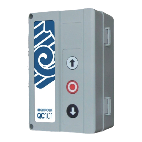
Summary of Contents for GAPOSA QC100
- Page 1 QC100 | 101 230 V~ SINGLE-PHASE CONTROL UNIT Made in Italy...
- Page 2 INDEX SAFETY WIRING POWER OPERATING LOGIC RADIO TRANSMITTERS’ PROGRAMMING DEVICES OPTOELECTRONIC BAR AND/OR PHOTOCELL COURTESY LIGHT AUTOMATIC CLOSING MODE CANCELLATION OF THE AUTOMATIC CLOSING MODE PROGRAMMING OF WORKING TIME EMERGENCY MODE WITH FAULTY BAR RESET ALERTS...
- Page 3 SAFETY These instructions contain important information on the installation and the use of the QC100/101 unit. Please keep them even after installation. Do not start installing the QC100/101 unit without having first read these instructions. The installation can only be done by a qualified technician.
- Page 4 ELECTRICAL CONNECTION 21 20 19 18 17 16 15 14 13 20 - 21 - 22 Power supply 1-phase (230 v~) (ground = 22) 17 - 18 - 19 Motor (comune = 18) 16 - 15 Flashing light [230V~] 14 - 13 Courtesy lamp (contact normally open - no) 12 - 11 Power supply external accessories (24 V~)
-
Page 5: Operating Logic
POWER When you activate the board the red LED switches on steadily for about 3 seconds. After about 1 second, the green LED will flash a number of times equal to the review. When the red LED switches off, the green LED switches on steadily indicating that the switch on procedure of the card is completed and now it is ready for operation. -
Page 6: Transmitters' Programming
TRANSMITTERS’ PROGRAMMING 1. Place the DIP 1 in ON position. Both the red and the green LED will be switched on with a fixed light 2.1 To associate a channel with a Start/Stop command send a signal from the transmitter. 2.2 To associate a channel with an Open command send a signal from the transmitter while holding down the UP button on the control unit. -
Page 7: Safety Devices
SAFETY DEVICES The safety of the board are managed via DIP 3 and 4: SAFETY LOGIC DIP 3 When an obstacle is detected during the way down the move- ment is reversed until the opening limit switch; It has no effect on the way up. - Page 8 OPTOELECTRONIC BAR AND/OR PHOTOCELL To connect the optoelectronic bar QCSE and the photocell, the latter must be connected in series to the digital signal of the bar as shown (DIP 4 in ON). GRD - White +12Vcc - Brown SIGNAL - Green To connect the the photocell, the latter must be connected as shown (DIP 4 in OFF).
- Page 9 INTEGRATED COURTESY LIGHT The courtesy lamp contact will activate ifself, after an opening input, once the door is completely closed and the operation time over. The contact of the courtesy light has two working modes: • switch on in case of opening and authomatical switch off after 3 minutes • switch on for two seconds while opening (useful to operate a lighting system).
- Page 10 AUTOMATIC CLOSING MODE The control includes, among its functions, the automatic closing after a set time. The automatic closing activates by programming the pause time and by choosing the “impulse” operating mode (DIP 2 in OFF). When the dead- man logic is active while closing, the automatic closing is excluded (DIP 2 in ON).
- Page 11 CANCELLATION OF THE AUTOMATIC CLOSING MODE This procedure clears the pause time and then excludes the automatic closing. 1. Put DIP 5 and 6 in OFF 2. Put DIP 5 in ON and within 3 seconds put it again in OFF. If cancellation has been accomplished correctly, the red LED will flash quickly and then switch off.
- Page 12 PROGRAMMING OF WORKING TIME The work time is the time it takes to perform a complete opening or closing operation. By performing this procedure the board automatically learns the stroke. Without programming, the working time lasts 30 sec. ATTENTION: During the programming procedure ensure that no obstacle activates the safety devices (photocells or safety edges) and stops the movement of the door.
- Page 13 EMERGENCY MODE WITH FAULTY BAR This mode allows the movement of the motor with dead-man control also in case the optoelectronic bar is active or faulty. Mode description: • The mode becomes operational after about 30 seconds from the coast activation (the count is reset if the bar returns to visibility) • The mode allows the movement of the motor in opening and closing in dead-man mode regardless of the position of the dip 2.
- Page 14 RESET Through the reset procedure: • all memorised transmitters will be deleted • the programming of pause time and of the stroke are reset to default conditions (working time of 30 seconds, automatic closing disabled). • the “Emergency mode with faulty bar” is also turned off. During the reset procedure, all controls are inhibited.
-
Page 15: Troubleshooting
ALERTS The following table shows the various light signals generated by the control unit with their meaning and possible operations to be performed. CONTROL UNIT FEEDBACK CONTROL UNIT STATUS GREEN LED RED LED SOLUTION READY FOR COMMANDS EXECUTION WAITING FOR AUTOMATIC SHORT SHUTDOWN EVERY CLOSING 3 SECONDS... - Page 16 GAPOSA srl - via Ete, 90 63900 Fermo - Italy T. +39.0734.220701 - info@gaposa.com...


Need help?
Do you have a question about the QC100 and is the answer not in the manual?
Questions and answers