Advertisement
Quick Links
INSTALLATION & SERVICING MANUAL
Models covered by these instructions
CXS 40 - 120
THE IDEAL
Concord CXS 40 - 120
CAUTION:
To avoid the possibility of injury during the installation, servicing or cleaning of ths appliance, care should be taken when handling edges
of sheet steel components.
Concord CXS 40 - 120 (Natural gas) B.G. Certified - P.I. No. 87/AQ/103 Destination Countries: GB & IE
CONTENTS
Air Supply
Boiler Assembly - exploded view
Boiler Clearances
Burner Assemblies - exploded views
CXS 40-90
CXS100-120
Casing Assembly
Chimney System
Commissioning
Controls
Electrical Connections
Electrical Supply
Fault Finding
Gas Safety Regulations
Gas Supply
Hydraulic Resistance
Initial Lighting
Installation
Mandatory Requirements
Option Kits
Pump
Servicing
Short List of Parts
Site Assembled Boilers
Static Head Requirements
System Connections
Ventilation
Water Circulation
Water Connections
Water Treatment
Wiring Diagrams
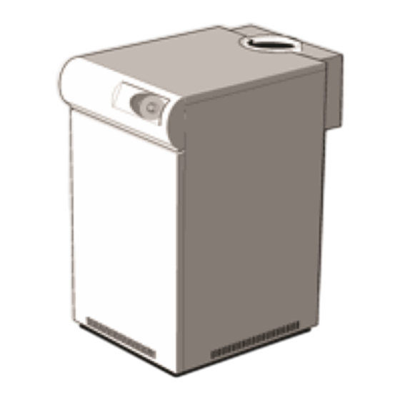
INTRODUCTION CONSTRUCTION
Concord CXS 40 - 120
Advertisement

Subscribe to Our Youtube Channel
Related Manuals for Ideal Boilers Concord CXS 40


Summary of Contents for Ideal Boilers Concord CXS 40
- Page 1 To avoid the possibility of injury during the installation, servicing or cleaning of ths appliance, care should be taken when handling edges of sheet steel components. Concord CXS 40 - 120 (Natural gas) B.G. Certified - P.I. No. 87/AQ/103 Destination Countries: GB & IE CONTENTS...
- Page 2 Failure to install appliances correctly could lead to prosecution. It is in your own interest, and that of safety, to ensure that the law is complied with. The Concord CXS 40-120 range of boilers has been tested and certified by British Gas to prEN656 for use with Natural gas only.
- Page 3 Table 2 - General Data Boiler Number of sections Flow tappings Rc (in. BSP) 2 × 2 at rear Return tappings Rc (in. BSP) 2 × 2 at rear Maximum static head metres (feet) 61.0 (200) 45.7 (150) Maximum pressure bar (p.s.i.) 6.0 (87) Gas inlet connection...
- Page 4 WATER CIRCULATION SYSTEM Due to the compact nature of the boiler the heat stored within the castings at the point of shutdown of the burner must be dissipated into the water circuit in order to avoid the overheat thermostat tripping. In order to allow pump operation after burner shutdown the boiler control box incorporates a pump overrun facility which operates for approximately 6 minutes after the burner shuts down and, in order to make use of this, the pump must be wired to the appropriate terminal L2 (pump) in the boiler control box.
- Page 5 Graph 2 - Hydraulic Resistance 2. CLEARANCES & DIMENSIONS Table 4 Boiler Size CXS 40 CXS 50 CXS 60 CXS 70 CXS 80 CXS 90 CXS 100 CXS 100 CXS 120 Front 750 (29 1/2) clearance (in) Rear 150 (6) 150 (6) 300 (12) 300 (12)
- Page 6 Clearance between boilers = 50mm Clearance at both ends of the multiple installation = 50mm∗ CXS 90,100, 110 & 120 Clearance between boilers = 100mm Clearance at both ends of the multiple installation = 100mm∗ Rear clearance: sufficient clearance should be given at the rear of the boiler for connection of gas and water pipework. ∗...
- Page 7 The information and guidance given below is not intended to override any requirements of either of the above publications or the requirements of the local authority, gas or water undertakings. Other British Standards applicable are BS.5422 & BS.6700. The information provided is based on the following assumptions: 1.
- Page 8 The appliance must be installed by a CORGI registered installer, identified by. The installation of the boiler must be in accordance with the relevant requirements of the Gas Safety Regulations, current I.E.E. (BS. 7671) Regulations, Model Water Bye-laws, local water authority bye-laws and it should also comply with any relevant requirements of the local gas supplier, local authority and the relevant British Standard Codes of practice and building regulations.
- Page 9 Safe, efficient and trouble-free operation of open flued gas boilers is vitally dependent on the provision of an adequate supply of fresh air to the room in which the appliance is installed. Ventilation by grilles communicating to the outside air is required. The minimum free area of these grilles must be in accordance with Tables 6 and 7.
- Page 10 This appliance must be efficiently earthed. A 230 V - 50 Hz mains supply is required, fused at 5 amps. Wiring external to the appliance MUST be in accordance with the I.E.E. (BS. 7671) Wiring Regulations and any local regulations which apply. For details of connections see Frame INSTALLATION...
- Page 11 3. Carton containing the installation pack. 4. Carton containing the control box and instruction books. CASING PACK contains • Front panel ........1 off • Side panel ........2 off • Top panel ........1 off • Flue brush ........1 off •...
- Page 12 2. Fit the 1″ tapped flange to the other lower rear connection using the gasket and M10 × 25mm screws and washers provided. 3. Temporarily screw the 2 handling bars (2″ pipe) into the top tappings and manoeuvre the boiler into position. 4.
- Page 13 10 FLUE CONNECTION 1. Complete the flue connection. 2. The boiler is designed to accept flues to BS. 835 and should be sealed with an approved boiler putty. 11 GAS CONNECTION 1. Connect the gas supply to the gas inlet pipe at the rear LH side of the boiler. Table 2 gives details of the inlet connection size and the minimum working pressures.
- Page 14 4. Fit 3 clips to the top of each side panel. 5. Fit the spire clips to the side casing panels. 6. Hook on the control box to side panels. Screw in self tapping screws at the bottom of the control box to fix it to the side panels. 7.
- Page 15 Ensure the phial is correctly seated in the correct pocket opposite side to the flow connection. Refer to Frame 9. Secure with the split pin provided. 8. Route the temperature sensing probe through the cable clips provided and into the thermostat pocket adjacent to the flow connection. Fit the plastic Heyco bush over the sensor lead at the line shown and insert it into the thermostat pocket.
- Page 16 Wiring should be in four core PVC insulated cable, not less than 0.75mm (24/0.2mm). All fuses must be ASTA approved to BS. 1362. The length of the conductor between the cord anchorage and the terminals must be such that the current carrying conductors become taut before the earthing conductor, if the cable or cord slips out of the cord anchorage.
- Page 17 16 ZONES WITH BI-DIRECTIONAL MOTORISED VALVES IMPORTANT: Terminal L2 may control the appropriate pump(s) directly, provided that the total running or starting current does not exceed 6A (resistive or inductive): if this rating would be exceeded, then appropriate switchgear must be used to control the pumps indirectly. Three zones are illustrated but the principles may be extended as required, provided the above conditions are met.
- Page 18 At the start of the next call for heat (or the next clock period) valves on zones not calling for heat will motor shut. Water circulation system - refer to page 5 17 ZONES WITH INDIVIDUALLY PUMPED ZONES (3 zones shown) IMPORTANT: Terminal L2 may control the appropriate pump(s) directly, provided that the total running or starting current does not exceed 6A (resistive or inductive): if this rating would be exceeded then appropriate switchgear must be used to control the pumps indirectly.
- Page 19 Three zones are illustrated but the principles may be extended as required, provided the above conditions are met. For each zone (except Zone 1) a relay with 2 C/O contacts is required. Overrun During overrun periods, Zone 1 pump performs the overrun facility; this zone, therefore, must satisfy the conditions in the foregoing paragraphs and Graph 1.
- Page 20 GENERAL Check that all drain cocks are closed, that any stop valves fitted to the flow and return pipes are open and that the system has been filled and properly vented. PURGING Check that the electricity supply is switched OFF. Remove the casing lower front panel.
- Page 21 21 MANIFOLD GAS PRESSURE The manifold setting pressure must now be checked and adjusted as necessary. It is essential to set the High Pressure first Start the adjustment procedure with the system cold, on full load and with all temperature controls set to maximum to avoid thermostatic shutdown. Remove the screw in the manifold setting pressure test point and connect a suitable gas pressure gauge.
- Page 22 Failure to follow this procedure may result in the correct burner pressure being set but the 2 gas valve governors not working correctly. CXS 110 - 120 Boilers The setting procedure must be done in 2 steps. The location of the manifold pressure adjusters (1 & 2) on the gas valves are shown below. Remove the dust cover and using a screwdriver screw in the adjuster (1) on the LH gas valve nearly fully.
- Page 23 25 HANDING OVER ROUTINE OPERATION Full instructions covering routine lighting and operation of the boiler are given on the Lighting and Operation Instruction Label located on the inside of the casing door. Draw the attention of the boiler owner or his representative to the Lighting and Operating Instruction Label on the inside of the casing door. Give a practical demonstration of the lighting and shutting down of the boiler.
- Page 24 Examine the burner assembly. Clean the burner bars by brushing them down with a stiff bristle (not wire) brush. Check each bar carefully to ensure that all flame ports are clear, that there are no cracks and that all surfaces are free from accumulated deposits. If available, an industrial vacuum cleaner may be useful to assist in this work.
- Page 25 4. Remove the 2 screws securing the electrode assembly and heat shield to the LH burner bracket and the 2 screws securing the detection electrode bracket to the RH burner. 5. Reassemble in reverse order. IMPORTANT: Care must be taken to prevent damage to the combustion chamber insulation when replacing burners. 31 BURNER AND CONTROLS ASSEMBLY - Exploded View - CXS 40 - 90 32 BURNER AND CONTROLS ASSEMBLY - Exploded View - CXS 100 - 120...
- Page 26 33 OVERHEAT THERMOSTAT 1. Remove the split pin from the overheat thermostat pocket and remove the phial. 2. Undo the 2 - M3 screws and remove the thermostat assembly from its fixing bracket. 3. Undo the backnut and the 2 - M3 screws and remove the top bracket. 4.
- Page 27 34 CONTROL BOX - Basic Boiler, Exploded View...
- Page 28 35. CONTROL SENSOR 1. Remove the casing top panel and lower front panel. 2. Remove the sensor from the thermostat pocket in the rear heat exchanger section by removing the Heyco bush. 3. Undo the 2 screws securing the control box front panel. Carefully lift up and lower it. 4.
- Page 29 1. Undo the thermostat knob retaining screw and pull off the knob. 2. Remove the lower front panel. 3. Undo the backnut and washer retaining the potentiometer. 4. Undo the 2 screws securing the control box front panel, lift it and carefully lower it. 5.
- Page 30 38 COMBUSTION CHAMBER INSULATION REPLACEMENT The insulation boards used in the combustion chambers of these products contain man-made fibres, refractory fillers, organic and inorganic binders and as such are deemed to be harmless to humans. Caradon Plumbing Limited, however, recommend that for your own comfort and to comply with good working practise the procedure described below is followed.
- Page 31 The site assembled boiler is supplied in the following packages: Combustion chamber/manifold/burner assembly. Platework package. Casing package. Controls box package with instruction books. End and centre sections. GENERAL The installation of the boiler must be in accordance with the Gas Safety (Installation and Use) Regulations 1994, amendments 1996 or rules in force, building regulations, I.E.E.
- Page 32 18. Insert the burner rear supports into the slots at the back of the combustion chamber. Lift the front of the burners over the injectors and pull forward to engage. 19. Fit the support angles (contained in the platework package) to the collector hood. The angle with the hole for the earth screw fits to the front. 20.
- Page 33 FAULT FINDING 41 BOILER CONTROL Before attempting any electrical fault finding ALWAYS carry out the preliminary electrical system checks as detailed in the Instructions for the British Gas Multimeter or other similar commercially available meter. The preliminary electrical system checks are the FIRST electrical checks to be carried out during a fault finding procedure. On completion of any service/fault finding task which has required the breaking and remaking of electrical connections the following checks MUST be repeated: a.
- Page 34 Before carrying out any Fault Finding, ensure that all internal controls are calling for heat and that the overheat thermostat has not operated. There should be 230V ± 10% available at the control box connection. 43 BOILER DOES NOT LIGHT 44 BOILER LIGHTS BUT GOES TO LOCKOUT...
- Page 35 45 BOILER GOES OUT ON OVERHEAT THERMOSTAT SHORT LIST OF PARTS The following are parts commonly required as replacements due to damage or expendability. Their failure or absence is likely to affect the safety and/or performance of this appliance. When ordering spare parts please quote: 1.
- Page 36 P.O. Box 103, National Ave, Kingston upon Hull, HU5 4JN. Telephone: 01482 492 251 Fax: 01482 448 858. Registration No. London 322 137. Registered Office: National Avenue, Kingston upon Hull, HU5 4JN. A subsidiary of Caradon plc Ideal Installer/Technical Helpline: 01482 498376...
Need help?
Do you have a question about the Concord CXS 40 and is the answer not in the manual?
Questions and answers