Table of Contents
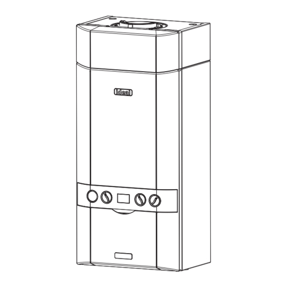
Advertisement
INSTALLATION
AND SERVICING
LOGIC Code Combi
26, 33, 38
For users guide see reverse of book
For details of document amendments, refer to page 3
When replacing any part on this appliance, use only spare parts that you can be
assured conform to the safety and performance specification that we require.
Do not use reconditioned or copy parts that have not been clearly authorised by Ideal.
For the very latest copy of literature for specification and maintenance practices visit our
website www.idealheating.com where you can download the relevant information in PDF format.
December 2010
UIN 206279 A01
Advertisement
Table of Contents

Related Manuals for Ideal Boilers LOGIC Code Combi 26


Summary of Contents for Ideal Boilers LOGIC Code Combi 26
- Page 1 INSTALLATION AND SERVICING LOGIC Code Combi 26, 33, 38 For users guide see reverse of book For details of document amendments, refer to page 3 When replacing any part on this appliance, use only spare parts that you can be assured conform to the safety and performance specification that we require.
- Page 2 Ideal Logic Code Combi - Installation and Servicing...
- Page 3 NOTEs FOR ThE INsTaLLER FOR aNy TEChNICaL qUERIEs pLEsE RINg ThE IDEaL INsTaLLER/TEChNICaL hELpLINE : 01482 445570 NOTE. BOILER REsET pROCEDURE - To reset boiler, turn mode knob to reset position and immediately turn knob back to required setting. The boiler will repeat the ignition sequence. DOCUMENT aMENDMENTs Relevant Installation changes implemented in this book from Mod Level ........a01 (Dec10) Ideal Stelrad Group reserve the right to vary specification without notice...
- Page 4 gENERaL Table 1 - general Data Ideal Logic Code Combi Gas supply 2H - G20 - 20mbar Gas Supply Connection 15mm copper compression Injector Size (mm) 4.15 4.65 Inlet Connection 15mm copper compression Outlet Connection 15mm copper compression Flow Connection Central Heating 22mm copper compression Return Connection...
- Page 5 gENERaL CONTENTs IDEAL LOGIC CODE COMBI air supply ..............9 Natural gas only Benchmark Commissioning Checklist ..... 62 Boiler size g.C. appliance No. pI No. Boiler Clearances ............10 (Benchmark No.) Boiler Exploded Diagram ........... 13 47-348-74 86-CL-151 Condensate Drain ........9, 22, 23, 38 47-348-75 86-CL-151 Electrical Connections ..........
-
Page 6: Safe Handling
gENERaL INTRODUCTION OpERaTION The Logic Code Combi range of boilers are wall mounted, full With no demand for CH, the boiler fires only when DHW is drawn sequence, automatic spark ignition, low water content, fanned off. flue, high efficiency, condensing, combination gas boilers. When there is a demand for CH, the heating system is supplied The boiler incorporates an additional recuperator to preheat the at the selected temperature of between 45... - Page 7 gENERaL OpTIONaL ExTRa KITs saFETy • Horizontal Flue Terminal (1000mm long). Current gas safety (installation and use) regulations or rules in force: • Flue Extension Ducts (1000mm long). 26-up to 9m The appliance is suitable only for installation in GB and IE and 33-up to 8m should be installed in accordance with the rules in force.
-
Page 8: Gas Supply
gENERaL gas sUppLy LOCaTION OF BOILER The local gas supplier should be consulted, at the installation The boiler must be installed on a flat and vertical internal wall, planning stage, in order to establish the availability of an adequate capable of adequately supporting the weight of the boiler and any supply of gas. -
Page 9: Air Supply
gENERaL TERMINaL 2. It is important that the position of the terminal allows the free passage of air across it at all times. The terminal assembly can be adapted to accommodate various 3. Minimum acceptable spacing from the terminal to obstructions wall thicknesses. - Page 10 gENERaL BOILER DIMENsIONs, sERVICEs & CLEaRaNCEs all dimensions in mm The boiler connections are made on the boiler connection tails. Bottom clearance Refer to Frame 30. Bottom clearance after installation can be reduced to 5mm. The following minimum clearances must be maintained for This must be obtained with an easily removable panel, to enable operation and servicing.
- Page 11 gENERaL sysTEM REqUIREMENTs - Central heating safety valve setting Notes Vessel charge pressure 0.5 to 0.75 a. The method of filling, refilling, topping up or flushing sealed primary hot water circuits from the mains via a temporary hose system pre-charge pressure bar None connection is only allowed if acceptable to the local water system volume...
-
Page 12: Domestic Hot Water
gENERaL sysTEM REqUIREMENTs - CONT sysTEM BaLaNCINg Domestic hot Water The boiler does not normally need a bypass but at least some radiators on the heating circuit, of load 1. The DHW service must be in accordance with BS5546 & BS6700. of at least 10% of the minimum boiler output, must 2. - Page 13 INsTaLLaTION BOILER assEMBLy - Exploded View Note that item numbers are linked to the spares list CH Return Valve Plate Heat Exchanger Recuperator Assy Electrode Detection CH Flow Valve Flow Sensor Hall Effect Air Duct Assy Ignitor Unit DHW Inlet & Outlet Flow Turbine Cartridge Recuperator Inlet Pipe Thermistor No Flow...
- Page 14 INsTaLLaTION UNpaCKINg The boiler is supplied fully assembled in one Pack A, together with a flue assembly for rear or side outlet in Pack B. Unpack and check the contents. pack a Contents Boiler Hardware Pack Box Wall Mounting Plate These Installation/Users Instructions Wall Mounting Template Turret Clamp...
- Page 15 INsTaLLaTION UNpaCKINg CONT’D pack B Contents Non-Telescopic Flue terminal Flue turret Rubber terminal wall seal Cutting Aid pack B Contents Telescopic (available as Option Kit Telescopic flue terminal Flue turret Rubber terminal wall seal Screw Sealing Tape isfu8751d DOOR paNEL REMOVaL pOD DOOR BOILER FRONT paNEL 1.
- Page 16 INsTaLLaTION 10 DETERMININg ThE FLUE LENgTh aND FLUE paCKs REqUIRED IMpORTaNT. The boiler MUST be installed in a vertical position Dimension x - Wall thickness. Dimension L - Wall thickness plus boiler spacing. Dimension s - Optional stand-off Frame depth 45mm. FLUE KITs pack B - supplied as standard pack B - optional telescopic...
- Page 17 INsTaLLaTION 11 DETERMININg ThE FLUE LENgTh aND FLUE paCKs REqUIRED CONT’D Notes. NON - TELEsCOpIC FLUE 1. It is recommended that a support bracket is fitted for every 1 metre of extension pipe Total Flue Length Dimension Flue used and a bracket should be used at every (measuring from CL of Turret to outside wall) joint, to ensure pipes are held at the correct Rear flue dim.
-
Page 18: Wall Mounting Template
INsTaLLaTION 13 WaLL MOUNTINg TEMpLaTE Extended centre line The wall mounting template is located on the internal protective packaging. V - See Diagram Below Note. The template shows the positions of the fixing holes and the rear flue hole centre for standard installation. Care MUST be taken to ensure the correct holes are drilled. - Page 19 INsTaLLaTION 15 TERMINaL WaLL sEaL assEMBLy / pOsITIONINg Prior to fitting the flue, the rubber terminal wall seal provided Once the flue is installed it is IMPORTANT that the rubber in the flue pack MUST be fitted to the flue terminal as shown terminal wall seal is pressed against the outside wall to create below in Figure 1.
- Page 20 INsTaLLaTION 17 sETTINg ThE FLUE - sIDE Wall thicknesses of 148 to 378mm non TelesCoPiC Flue - Wall thickness of 115mm to 440mm Notes. If using the extension ducts go to Frame 18. 1. Measure and note side flue length L. Refer to Frame 10. 2.
- Page 21 INsTaLLaTION 19 FLUE ExTENsION DUCTs - continued Use a maximum of 9m extended flue ONLY (26) Use a maximum of 8m extended flue ONLY (33) Use a maximum of 6m extended flue ONLY (38) general arrangement Flue length 1. A maximum number of extension ducts are possible for each boiler output with one suitably cut. 9 extension ducts for 26 Extension flue 8 extension ducts for 33 6 extension ducts for 38 Note.
-
Page 22: Mounting The Boiler
INsTaLLaTION 21 FITTINg ThE WaLL MOUNTINg pLaTE 22 MOUNTINg ThE BOILER 1. Ensure the plastic plugs are removed from both the CH Screw the wall mounting plate to the wall using 2 wall plugs and DHW connections before mounting the boiler. (previously fitted) with the 2 screws provided. - Page 23 INsTaLLaTION 24 CONDENsaTE pIpE TERMINaTION CONFIgURaTIONs notes: all exTernal PiPe runs MusT Be in aCCorDanCe WiTh Bs 6798 1. INTERNaL TO sINK WasTE UpsTREaM OF sINK WasTE TRap BOILER Open end of pipe direct into gulley below grating but above water level cla7771a Ground Level DRAIN...
-
Page 24: Connecting The Flue To The Boiler
INsTaLLaTION 25 CONNECTINg ThE FLUE TO ThE BOILER noTe. siDe Flue Notes. Select the orientation • Before fitting the flue turret fill the condensate before inserting turret into trap within the boiler by pouring a cupful of boiler flue manifold. water into the flue outlet. -
Page 25: Fitting The Optional Roof Flue Kit (Flat Or Pitched)
INsTaLLaTION 26 FITTINg ThE OpTIONaL ROOF FLUE KIT (Flat or pitched) Note. A flat or pitched roof flashing plate (not supplied) is required before proceeding with the installation of this kit. This kit is suitable for both flat and pitched roof terminations, using a concentric flue to run vertically from the top of the boiler and terminating above roof level. -
Page 26: Flue Terminal Position
INsTaLLaTION 28 FLUE TERMINaL pOsITION The terminal should be positioned so that products of combustion can safely disperse at all times. pluming may occur at the termination so, where possible, terminal positions where this could cause a nuisance should be avoided. Minimum dimensions are shown below 300mm 625mm... -
Page 27: Assembling The Roof Flue Kit
INsTaLLaTION 29 assEMBLINg ThE ROOF FLUE KIT Determine the correct height that the flue should terminate above the roof. If after calculating or measuring the overall flue height from the top of the boiler, it is necessary to cut both pipes of assembly A, then ensure they are cut equally leaving the inner flue tube longer than the outer air tube as supplied. -
Page 28: Connections & Filling
INsTaLLaTION 30 CONNECTIONs & FILLINg NOTEs. Note. The domestic hot water flow rate is Ensure all boss blanking plugs are removed before connecting hardware. Each automatically regulated to a maximum: valve must be fitted to the correct boss as shown in the picture. 26 = 10.7 l/m (2.4 gpm) Ensure each union is fitted with fibre seals provided. -
Page 29: Electrical Connections
INsTaLLaTION 31 ELECTRICaL CONNECTIONs Wiring should be 3 core PVC insulated cable, not less than Warning. This appliance MUST be earthed. 0.75mm (24 x 0.2mm), and to BS 6500 Table 16. For IE reference should be made to the current ETCI rules for A mains supply of 230Vac ~ 50 Hz is required. -
Page 30: External Electrical Controls
INsTaLLaTION 33 INTERNaL WIRINg DIAGRAM B DIAGRAM A Room External Internal Timer or Room Stat or Timer Stat Programmable Room Stat Prog. Room Stat ROOM ROOM STAT/ STAT/ TIMER TIMER Optional Optional Frost Stat Frost Stat FROST FROST STAT STAT OPTIONAL OPTIONAL Separate Timer and Room Stat... - Page 31 INsTaLLaTION 36 WIRINg DIagRaM Ideal Logic Code Combi - Installation and Servicing...
-
Page 32: Commissioning And Testing
INsTaLLaTION 37 COMMIssIONINg aND TEsTINg a. Electrical Installation B. gas Installation 1. Checks to ensure electrical safety should be carried out by a 1. The whole of the gas installation, including the meter, competent person. should be inspected and tested for tightness and purged in accordance with the recommendations of BS. -
Page 33: Initial Lighting
INsTaLLaTION 38 INITIaL LIghTINg Legend a. Blank B. DHW temperature control C. CH temperature control D. Off/Summer/Winter/Reset Control E. Boiler Status F. Burner ‘on’ indicator g. CH Flow Isolating Valve h. Pressure Gauge J. Gas Inlet Pressure Test Point K. Gas Service Cock L. - Page 34 INsTaLLaTION 39 gENERaL ChECKs Make the following checks for correct operation in: DOMEsTIC hOT WaTER (DhW) MODE WaTER CIRCULaTION sysTEM 1. Fully open all DHW taps in turn and ensure that water flows 1. With the system COLD, check that the initial pressure is freely from them.
-
Page 35: Handing Over
INsTaLLaTION 40 REsET pROCEDURE To reset boiler, turn the mode control knob (D) to reset position and immediately turn knob back to required setting. The boiler will repeat the ignition sequence. Legend a. Blank D. Off/Summer/Winter/Reset Control B. DHW temperature control E. -
Page 36: Servicing Schedule
sERVICINg 42 sERVICINg sChEDULE For the very latest copy of literature for specification & maintenance practices, visit our website www.idealheating.com, where you will be able to download the relevant information. N.B. Technical Bulletins are also available on www.idealheating.com. Warning. always turn OFF the gas supply at the gas service cock, and switch OFF and disconnect the electricity supply to the appliance before servicing. - Page 37 sERVICINg 43 BOILER TOp pOD DOOR & FRONT paNEL REMOVaL / REpLaCEMENT TOp pOD DOOR REMOVaL FRONT paNEL REMOVaL 1. Loosen the two screws securing the pod door. 1. Loosen the two screws retaining the front panel. 2. Remove the pod door lifting upwards & pulling forward. 2.
-
Page 38: Burner Removal And Cleaning
sERVICINg 45 BURNER REMOVaL aND CLEaNINg 1. Ensure the sump is fully drained 2. Undo the two screws and remove the sump cover retaining the lower flue manifold. 3. Lift the manifold to clear the bottom sealing gasket and remove manifold. -
Page 39: Cleaning The Heat Exchanger
sERVICINg 47 CLEaNINg ThE hEaT ExChaNgER note: Ensure the condensate trap/siphon is fully drained before cleaning. Refer to Ignition Electrode Flame Detection Frame 59. 1. Remove ignition and flame detection electrodes. Refer to Frames 54 & 55. 2. It is advisable to replace the sump cover prior to the water flush process. -
Page 40: Replacement Of Components
sERVICINg 49 REpLaCEMENT OF COMpONENTs gENERaL After replacing ANY component check operation of the boiler, including gas soundness, gas rate and combustion When replacing aNy component test. 1. Isolate the electricity supply. IMpORTaNT. When work is complete, the front panel must be correctly 2. -
Page 41: Burner Injector Replacement
sERVICINg 51 BURNER INJECTOR REpLaCEMENT 1. Refer to Frame 49. 2. Disconnect the electrical leads from the fan. 3. Undo the gas pipe union connection to the injector housing. 4. Loosen the screw retaining the fan mounting bracket. 5. Lift and remove the fan and venturi assembly. 6. -
Page 42: Ignition Electrode Replacement
sERVICINg 53 CONTROL ThERMIsTOR & RETURN ThERMIsTOR RENEWaL 1. Refer to Frame 49. 2. Unclip the control thermistor from the flow pipe and withdraw it from the boiler. 3. Unclip the return thermistor from the return pipe and withdraw it from the boiler. -
Page 43: Flame Detection Electrode Replacement
sERVICINg 55 FLaME DETECTION ELECTRODE REpLaCEMENT 1. Refer to Frame 49. 2. Remove the burner. Refer to Frame 52. 3. Unplug the flame detection lead from the electrode. Flame Detection Electrode 4. Remove the 2 screws retaining the detection electrode. 5. -
Page 44: Gas Control Valve Replacement
sERVICINg 57 gas CONTROL VaLVE REpLaCEMENT 1. Refer to Frame 49. 2. Unplug the electrical lead connection from the gas control valve and disconnect the earth wire. 3. Undo the union nut on the outlet of the gas control valve. 4. - Page 45 sERVICINg 59 CONDENsaTE TRap/sIphON REpLaCEMENT 1. Refer to Frame 49. Note: Ensure condensate trap is fully drained before removal. 2. Pull off the rubber pipe at the sump drain. 3. Disconnect the condensate drain pipe. 4. Remove the cleaning plug 5.
-
Page 46: User Control Pcb Replacement
sERVICINg 61 UsER CONTROL pCB REpLaCEMENT Note. Fit the earth strap provided with the PCB to your wrist and a suitable earth on the boiler chassis. 1. Refer to Frame 49. 2. Remove the main PCB, refer to Frame 60. 3. - Page 47 sERVICINg 63 DRaININg ThE BOILER Filling Loop CENTRaL hEaTINg CIRCUIT 1. Refer to Frame 49. 2. Close all the CH water isolating valves on the boiler inlet. 3. To drain the primary heat exchanger circuit: Open the drain valve and attach a length of hose to the CH drain point. 4.
-
Page 48: Pump Automatic Air Vent Replacement
sERVICINg 66 pUMp aUTOMaTIC aIR VENT REpLaCEMENT 1. Refer to Frame 49. 2. Drain the boiler. Refer to Frame 63. 3. Remove the expansion vessel. Refer to Frame 75. Dust Cap 4. Firstly, increase access area by disconnecting the 22mm pipe connection at top of pump chamber and bottom of heat exchanger and remove pipe Refer to Frame 65 (no’s 5,6 &... -
Page 49: Diverter Valve Internal Cartridge Replacement
sERVICINg 68 DIVERTER VaLVE INTERNaL CaRTRIDgE REpLaCEMENT FRONT CaRTRIDgE REpLaCEMENT REaR CaRTRIDgE REpLaCEMENT 1. Refer to Frame 49. 1. Refer to Frame 49. 2. Drain the boiler. Refer to Frame 63. 2. Drain the boiler. Refer to Frame 63. 3. Remove the diverter valve head. Refer 3. - Page 50 sERVICINg 71 Ch WaTER pREssURE sENsOR REpLaCEMENT 1. Refer to Frame 49. 2. Drain the boiler. Refer to Frame 63. 3. Remove condensate trap/siphon. Refer to Frame 59. 4. Using a suitable tool pull out the retaining clip. 5. Pull the pressure sensor upwards to remove. 6.
-
Page 51: Heat Engine Renewal
sERVICINg 74 hEaT ENgINE RENEWaL Refer also to Frame 6 - ‘Boiler Exploded View’ IMpORTaNT Before starting the removal procedure, protect the gas and electrical controls with a waterproof sheet or plastic bag. 1. Refer to Frame 49. 2. Drain the boiler. Refer to Frame 63. 3. -
Page 52: Boiler Sealing Panel Seal Replacement
sERVICINg 76 BOILER sEaLINg paNEL sEaL REpLaCEMENT 1. Refer to Frame 49. 2. Remove the old seal from the casing and thoroughly clean the casing surfaces. 3. Fit the new seal, ensuring the bottom joint provides an air tight seal. 4. - Page 53 sERVICINg 78 FaULT FINDINg ChaRT MaIN MENU gO TO FRaME 79 - aLTERNaTINg ‘L’ and ‘1’ FLOW TEMpERaTURE OVERhEaT LOCKOUT gO TO FRaME 80 - aLTERNaTINg ‘L’ and ‘2’ IgNITION LOCKOUT gO TO FRaME 81 - aLTERNaTINg ‘L’ and ‘3’ NO WaTER FLOW LOCKOUT 5 REsETs WIThIN 15 MINs - aLTERNaTINg ‘L’...
-
Page 54: Fault Finding
FaULT FINDINg 79 aLTERNaTINg ‘L’ aND ‘1’ - FLOW TEMpERaTURE OVERhEaT LOCKOUT Is the Boiler and CH System filled with water and all Fill and vent the system and open all isolation and radiator valves open? isolation valves, then reset boiler Is the Flow/Return Differential across the Boiler in Check that the Pump is rotating freely. - Page 55 FaULT FINDINg 81 aLTERNaTINg ‘L’ aND ‘3’ - NO WaTER FLOW LOCKOUT Is the Boiler and CH System filled with water and all Fill and vent the system and open all isolation and radiator valves open? isolation valves, reset the boiler. Check pump connection and check Reset the boiler.
- Page 56 FaULT FINDINg 84 aLTERNaTINg ‘F’ aND ‘2’ - FLaME LOss Is the Gas Working Pressure avail- Does the boiler ignite for a short Check gas supply and able at the Boiler Inlet (18 mbar)? time and then extinguish? rectify fault Check wiring from gas Is 215Vdc supply available at the Gas valve to PCB for continuity.
- Page 57 FaULT FINDINg 87 aLTERNaTINg ‘F’ aND ‘5’ - RETURN ThERMIsTOR FaULT Remove the Return Thermistor from the CH Return Pipe and disconnect the wires. Check the resistance using a suitable multimeter Fit a new Thermistor connected across the thermistor’s terminal pins. At 25 expect 9,700 - 10,300...
- Page 58 FaULT FINDINg 90 aLTERNaTINg ‘c’ aND ‘2’ - BCC FaULT (BOILER ChIp CaRD) Securely insert the correct BCC for the boiler Is the correct BCC for the boiler securely inserted into the into the PCB and after switching power on and slot at the rear right of the PCB? ‘c0’...
- Page 59 FaULT FINDINg 92 NO hW BUT Ch ON YES Is hot and cold Is the red neon Does the display show “d” when a tap is on? illuminated on the turbine pipework crossed? sensor? Adjust flow rates to achieve 35º Are the flow rates correct as per Frame 2.
-
Page 60: Short List Of Parts
shORT LIsT OF paRTs When ordering spares please quote: The following are parts commonly required due to damage or expendability. Their failure or absence is likely to affect safety or 1. Boiler model performance of this appliance. 2. Appliance G.C. No. The list is extracted from the British Gas List of Parts, which con- 3. - Page 62 Failure to install and commission according to the manufacturer’s instructions and complete this Benchmark Commissioning Checklist will invalidate the warranty. This does not affect he customer’s statutory rights. Gas Safe Register Number Telephone Number If yes, and if required by the manufacturer, has a water scale reducer been fitted? If the condensate pipe terminates externally has the pipe diameter been increased and weatherproof insulation fitted?
- Page 63 Gas Safe Register Number Gas Safe Register Number Gas Safe Register Number Gas Safe Register Number Gas Safe Register Number Gas Safe Register Number Gas Safe Register Number Gas Safe Register Number Gas Safe Register Number Gas Safe Register Number...
- Page 64 For additional fault finding advice please visit Ideal Boiler’s website www.idealheating.com Technical Training The Ideal Technical Training Centre offers a series of first class training courses for domestic, commercial and industrial heating installers, engineers and system specifiers. For details of courses please ring:....01482 498 432 Manufactured under an ISO 9001 the code of practice for the installation, registered quality management system commissioning &...
Need help?
Do you have a question about the LOGIC Code Combi 26 and is the answer not in the manual?
Questions and answers