Table of Contents
Advertisement
Advertisement
Table of Contents

Related Manuals for Ideal Boilers CF3/100


Summary of Contents for Ideal Boilers CF3/100
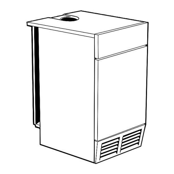
- Page 2 Mexico: The Floor Standing Gas Boiler The Ideal Mexico is a range of cast iron floor standing gas central heating boilers. Both balanced or conventional flue versions are available. A complete range of both natural gas and propane models. The range offers Super models and, for when space is tight, there are Slimline models available.
- Page 3 GENERAL Table 1 - General Data Boiler Size CF 3/100 CF 3/125 CF 3/140 Gas Supply Connection in. BSP Rc 1/2 (1/2) Rc 3/4 (3/4) Flue Connection mm (in.) 125 (5) 150 (6) 150 (6) Number of Boiler Sections Flow and Return Connections Rc 1 (1"...
-
Page 4: Table Of Contents
GENERAL Mexico Super CF Natural Gas only Mexico Super CF 3/100 ... G.C. No. 41 348 18 Appliance type: B Mexico Super CF 3/125 ... G.C. No. 41 348 20 Certified - P.I. No. 87 AT 15 Mexico Super CF 3/140 ... G.C. No. 41 348 21 Destination Countries: GB, IE INTRODUCTION CONTENTS... -
Page 5: Gas Safety
GENERAL The boiler may be fitted on a combustible floor. GAS SAFETY Gas safety (Installation and Use) Regulations, 1994 Insulation is not necessary, unless required by the local amendments 1996 or rules in force. authority. It is law that all gas appliances are installed by a CORGI The boiler must not be fitted outside. -
Page 6: Boiler Clearances
GENERAL 1 BOILER WATER CONNECTIONS 1. This appliance is NOT suitable for use in a direct hot water system. 2. If the boiler is to be used on a sealed system, an Overheat Thermostat Kit is available and must be installed in accordance with the instructions supplied with the kit. -
Page 7: Air Supply
GENERAL This device is not a substitute for an independently mounted FLUE INSTALLATION carbon monoxide detector. The flue must be installed in accordance with the recommendations of BS. 5440:1. In cases of repeated or continuous shutdown a competent person should be called to investigate and rectify the condition The following notes are intended for general guidance: causing this and carry out an operational test after each 1. -
Page 8: Electrical Supply
GENERAL Table 4 - High and low vent areas The central heating system should be in accordance with BS. 6798 and, in addition, for smallbore and microbore systems, Boiler Air from room/internal Air direct from outside BS. 5449:1. space cm (in. -
Page 9: Boiler Assembly - Exploded View
INSTALLATION 3 BOILER ASSEMBLY - Exploded View Mexico Super CF 3/100 shown (with the casing removed) 13. Front plate assy. LEGEND 21. Gas valve. 1. Heat exchanger. 23. Piezo spark generator. 2. End section. 27. Gas cock. 3. Middle section. 33. - Page 10 INSTALLATION UNPACKING The boiler is supplied fully assembled in Pack A. Unpack and check the contents. Pack A Contents complete boiler the Hardware Pack (listed separately below) these Installation and Servicing Instructions User's Instructions. HARDWARE PACK 1" BSP plugs - 6 off Thermostat pocket -1 off 1"...
-
Page 11: Boiler Casing Removal
INSTALLATION BOILER CASING REMOVAL To install the boiler the casing MUST be removed. 1. Lift off the lower front panel. 2. Remove 2 screws and lift off the grille assembly. 3. Remove the gas valve cover by removing the retaining screw. -
Page 12: Preparing The Boiler
INSTALLATION PREPARING THE BOILER Notes. Table 5 - Fully Pumped Systems • Before placing the boiler in the selected position any gas and water connections at the rear of the boiler Connections - as viewed at front Thermostat position should be prepared, due to the possible lack of Back Section Front Section access. -
Page 13: Pump
INSTALLATION WATER CONNECTION 1. Connect the system flow and return pipework Gravity pipework and connections must be at least: to the boiler as appropriate. Refer to Frames CF 100 - CF 125 28 mm (1" BSP) 10 and 11 for guidance on system design. CF 140 only 35 mm "... -
Page 14: Flue Connection
INSTALLATION 11 GRAVITY HOT WATER & PUMPED CENTRAL HEATING CF 3/140 ONLY Cylinder capacity: 1. Separate flow and return connections are used for 160 litres minimum each service. All possible configurations are given 360 litres maximum in Frame 7 and ONLY those shown should be used. -
Page 15: Electrical Connections
INSTALLATION 13 ELECTRICAL CONNECTIONS WARNING. Connection must be made in a way that allows complete The appliance MUST be efficiently earthed. isolation of the electrical supply - such as a double pole switch, having a 3mm (1/8") contact separation in both poles, A mains supply of 230 V ~ 50 Hz fused at 3A is required. -
Page 16: System Electrical Diagrams
INSTALLATION 16 PICTORIAL WIRING LEGEND blue black brown yellow/green 17 MID POSITION VALVE Pumped only Notes. 1. Some earth wires are omitted for clarity. Ensure proper earth continuity when wiring. 2. Numbering of terminals on thermostats is specific to the manufacturer. 3. -
Page 17: Frost Protection
INSTALLATION 18 TWO SPRING CLOSED VALVES Pumped only Notes. 1. Some earth wires are omitted for clarity. Ensure proper earth continuity when wiring. 2. Numbering of terminals on thermostats is specific to the manufacturer. 3. This is a fully controlled system - set the boiler thermostat to maximum. 4. -
Page 18: Fitting The Casing
INSTALLATION 21 FITTING THE CASING 1. Offer up the LH side panel, locating it with the peg in the baseplate, and push the panel back. 2. Secure the panel to the baseplate and collector hood. 3. Repeat steps 1 and 2 to refit the RH side panel. -
Page 19: Initial Lighting
INSTALLATION 23 INITIAL LIGHTING LEGEND E Gas service cock. Boiler controls A Gas control knob. F Sightglass. B Burner pressure test point. G Piezo ignition button. C Main burner pressure H Boiler thermostat knob. adjuster. J Overheat thermostat D Inlet pressure test point. (optional) reset button. -
Page 20: Handing Over
INSTALLATION 25 GENERAL CHECKS Make the following checks for correct operation: 4. Water circulation System a. With the system HOT, examine all water connections for 1. Turn the boiler thermostat OFF and ON to check that the soundness. main burner is extinguished and relit in response. b. -
Page 21: Servicing
SERVICING 27 SCHEDULE To ensure the continued safe and efficient operation of the g. Check that the flue is unobstructed and that the flue appliance, it is recommended that it is checked at regular system, including the flue cleanout cover, is sealed intervals and serviced as necessary. -
Page 22: Burner And Controls Assembly Removal
SERVICING 29 BURNER AND CONTROLS ASSEMBLY REMOVAL 1. Lift off the front panel and remove the grille assembly from the casing. 2. Undo the gas service cock union nut. 3. Remove the 4 wing nuts and withdraw the burner and controls assembly, complete, from the boiler. -
Page 23: Gas Pressure Adjustment
SERVICING 32 CLEANING THE LOWER FRONT PANEL LINT ARRESTING GAUZE 1. Unclip the gauze from the grille assembly and lift it clear of the bottom return edge. 2. Clean the gauze to remove any deposits of lint or fluff. 3. Refit the gauze by entering the bottom edge behind the grille return edge and engaging the top in the clips. -
Page 24: Replacement Of Parts
SERVICING REPLACEMENT OF PARTS 36 GENERAL 37 SIGHTGLASS REPLACEMENT When replacing any component: 1. Unfasten the 2 M5 hexagon nuts and washers. Remove the assembly from the front plate. 1. Isolate the electricity supply. 2. Fit the new sightglass and re-assemble, as 2. -
Page 25: Control Thermostat Replacement
SERVICING 40 CONTROL THERMOSTAT REPLACEMENT 1. Lift off the front door. Refer to Frame 28. 2. Pull off the thermostat knob. 3. Remove the 2 screws and pull down the control panel so that the tabs clear the top panel. 4. -
Page 26: Ignition Lead Replacement
SERVICING 42 IGNITION LEAD REPLACEMENT 1. Lift off front panel and remove the grille assembly. Refer to Frames 28 & 29. Undo the gas cock union and the 4 wing nuts to remove the burner / controls assembly. 2. Remove the purse clip. 3. -
Page 27: Ignition Electrode Replacement
SERVICING 44 IGNITION ELECTRODE REPLACEMENT Detail of pilot burner assembly 1. Lift off front panel and remove the grille assembly - refer to Frames 28 & 29. Undo the gas cock union and the 4 wing nuts to remove the burner / controls assembly. 2. -
Page 28: Main Burner Replacement
SERVICING 46 MAIN BURNER REPLACEMENT 4. Remove the 2 screws securing the pilot burner and pull the assembly clear of the main burner. 1. Lift off front lower panel and remove the grille assembly. 5. Remove the 2 nuts and washers securing the Refer to Frame 29. -
Page 29: Gas Valve Replacement
SERVICING 48 GAS VALVE REPLACEMENT 1. Lift off the front panel and remove the grille assembly. Refer to Frames 28 & 29. Remove the burner and controls assembly. 2. Undo the pilot supply connection. 3. Undo the thermocouple connection. 4. Unscrew the gas inlet pipe from the valve. -
Page 30: Fault Finding
FAULT FINDING Detailed instructions on the cleaning and adjustment or Before attempting any electrical fault finding ALWAYS carry replacement of faulty components are contained in the out preliminary electrical system checks, i.e. earth continuity, 'Servicing' section of this publication. polarity and resistance to earth using a suitable meter. 50 PILOT WILL NOT LIGHT Check that the gap between the electrode and the pilot burner is 3-4 mm. -
Page 31: Short List Of Parts
SHORT LIST OF PARTS The following are parts commonly required as replacement When ordering spares please quote: components, due to damage or expendability. Their failure or absence 1. Boiler model is likely to affect safety or performance of this appliance. 2. - Page 32 LIST OF PARTS 53 SHORT PARTS 54 BOILER CONTROL PANEL - Exploded View Legend 29. Controls panel complete assy. 30. Control box. 31. Boiler control thermostat. 32. Thermostat knob. 35. Controls panel. 36. Magnetic strip. 37. Controls front panel. Mexico Super CF 3/100, 3/125, 3/140 - Installation...
-
Page 33: Burner Assembly - Exploded View
LIST OF PARTS 55 BURNER AND CONTROLS ASSEMBLY - Exploded View Legend 13. Front plate. 14. Sightglass. 15. Burner manifold. 16. Pilot pipe. 17. Burner. 18. Burner injector - 2 off. 19. Pilot burner. 21. Gas valve. 22. 'O' ring. 23. - Page 34 THIS SYMBOL IS YOUR ASSURANCE OF QUALITY The code of practice for the installation, commissioning & servicing of central heating systems These appliances are designed for use with Natural CERTIFIED PRODUCT Gas only. They have been tested and conform with Manufactured under a BS EN ISO 9001: 1994 the provisions of BS.
- Page 35 Your feedback and your chance to win a free boiler At Ideal we've been leaders in the design and engineering of robust and reliable boilers for over 90 years. We want to continue as leaders by listening to your suggestions for how to improve our boilers and our service. We'll be giving away a free boiler for the five best ideas every year (to be selected by our Technical Director).
- Page 36 Further information If you would like information about Ideal Boilers please complete this sheet and fax it to us on 01482 498699 or post it to Caradon Plumbing Limited, PO Box 103, National Avenue, Kingston upon Hull, HU5 4JN. Installer details...
Need help?
Do you have a question about the CF3/100 and is the answer not in the manual?
Questions and answers