Advertisement
Quick Links
INSTALLATION & SERVICING MANUAL
Models covered by these instructions
CXC 40
CXC 70
CXC 94
CXC 116
THE IDEAL
Concord CXC 48 - 116
CAUTION:
To avoid the possibility of injury during the installation, servicing or cleaning of this appliance, care should be taken when handling
edges of sheet steel components.
Concord CXC 48-116 (Natural gas)
CONTENTS
Air Supply
Boiler Assembly - exploded view
Boiler Clearances
Burner Assemblies - exploded views
CXC 48-70
CXC 94-116
Casing Assembly
Commissioning
Condensate Drain Connection
Controls
Electrical Connections
Electrical Supply
Fault Finding
Flue System
Gas Connections
Gas Safety Regulations
Gas Supply
Hydraulic Resistance
Initial Lighting
Installation
Mandatory Requirements
Option Kits
Pump
Servicing
Short List of Parts
Static Head Requirements
Ventilation
Concord CXC 40
Concord CXC 70
Concord CXC 94
Concord CXC 116
B.G.
Certified -
P.I. No.
87/AQ/340
Destination
Countries:
GB and IE
Advertisement

Subscribe to Our Youtube Channel
Related Manuals for Ideal Boilers Concord CXC 40


Summary of Contents for Ideal Boilers Concord CXC 40
- Page 1 INSTALLATION & SERVICING MANUAL Models covered by these instructions CXC 40 Concord CXC 40 CXC 70 Concord CXC 70 CXC 94 Concord CXC 94 CXC 116 Concord CXC 116 THE IDEAL Concord CXC 48 - 116 CAUTION: To avoid the possibility of injury during the installation, servicing or cleaning of this appliance, care should be taken when handling edges of sheet steel components.
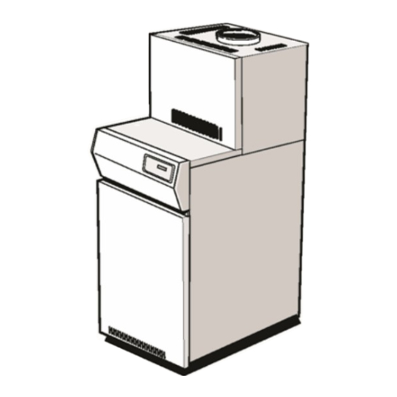
- Page 2 Water Circulation Water Connections Water Treatment Wiring Diagrams INTRODUCTION CONSTRUCTION BOILER BODY The Concord CXC boiler consists of 2 basic parts; a conventional Concord CXD boiler; plus an additional heat exchanger. The Concord CXC boiler body is constructed from cast iron sections, insulated by a foil backed fibre glass blanket. It is mounted on a sheet steel combustion chamber.
- Page 3 Boiler CXC 48 CXC 70 CXC 94 CXC 116 mbar 11.7 11.8 10.7 11.5 Manifold setting pressure High Rate in.w.g. Seasonal efficiency (SEDBUK)∗ [85.8]% [85.5]% [86.2]% [85.7]% ∗ The value is used in the UK government's Standard Assessment Procedure (SAP) for energy rating of dwellings. The test data from which it has been calculated have been certified by BGplc 0087.
- Page 4 Remote Indication Board (volt free): This provides the ability for remote indication of lockout and overheat conditions. Outside Sensor: This kit provides a sensor for temperature compensation when the outside temperature changes. Each boiler needs to be individually switched on therefore a sensor is required per boiler. DUTY The range of boilers is suitable for: Combined indirect pumped domestic hot water and central heating systems;...
- Page 5 Graph 2 - Heat Load/Water Volume Graph 3 - Hydraulic Resistance 2 CLEARANCES & DIMENSIONS POSITION OF BOILER Minimum clearances required from walls or other fixed objects to allow for the free access of combustion air are shown in Table 4 above.
- Page 6 Boiler Size CXC 48 CXC 70 CXC 94 CXC 116 Front clearance mm (in) 750 (29 ½) Rear clearance mm (in) 200 (8) see text Side clearance mm (in) 50 (2) 50 (2) 50 (2) 100 (4) 846(33 Dimension A mm (in) 723(28½) 969(38 1/8)
- Page 7 The wiring diagrams in Frames illustrate the control methods for achieving the above. 3. Pump selection should take account of the hydraulic resistance given in Graph 3. PUMP POSITIONS Whenever practically possible the circulating pump(s) should be positioned so that it pressurises the system being served. The vertical distance between the pump(s) and any cold feed and expansion cistern MUST comply with the pump manufacturers requirements in order to avoid cavitation.
- Page 8 MINIMUM FLOW OF WATER - Refer to Table 5 The system design must provide for an adequate flow rate through the boiler at all times when the boiler is firing. The minimum flow rate should correspond to a temperature difference across the boiler flow and return of 35°C (63°F), assessed at catalogue rating. It is essential that the main pump and shunt pump both overrun to dissipate the residual heat in the primary heat exchanger.
- Page 9 Pressure vessels used must comply with BS. 4814 and must be sized on the basis of the total system volume and initial charge pressure. Initial minimum charge pressure should not be less than 0.5 bar (7.2 psi) and must take account of static head and specification of the pressurising equipment.
- Page 10 Safe, efficient and trouble-free operation of conventionally flued gas boilers is vitally dependent on the provision of an adequate supply of fresh air to the room in which the appliance is installed. Ventilation by grilles communicating directly with the outside air is required at both high and low levels.
- Page 11 6 PACKAGING The Concord CXC boiler is despatched from the factory fully assembled except for the casing, controls and installation packs which are packed separately within the same wooden crate as the boiler. CONTROLS PACK contains Controls box complete ..1 off Controls installation pack ...
- Page 12 Upper middle rear panel ..1 off. Lower middle rear panel ..1 off. 7 PACKAGING AND BOILER REMOVAL 1. Remove the jacket carton and outer packaging frame. 2. Remove the jacket pack support frame. 3. Remove the controls package and installation pack. 4.
- Page 13 6. Position the overheat thermostat phial into the LH side thermostat pocket. The illustration shows the rear of the boiler with theflow and relative overheat thermostat position. Ensure that the overheat thermostat phial is correctly secured in the pocket. Refer to Frame 9 CONDENSATE DRAIN CONNECTION The condensate drain must be 1 ¼″...
- Page 14 The 150mm (6″) flue should conform to BS.715: Section 2 Stainless Steel or be of equivalent corrosion resistance. The flue must be designed to have no greater resistance than that of 30m of straight, smooth 150mm (6″) pipe. All joints must be impervious to condensate leakage. 11 GAS CONNECTION 1.
- Page 15 4. Screw lower side panel to support angles. Repeat for other side. 5. Fit clips to the top of each side panel. 6. Fit the spire clips to the side casing panels. 7. Hook on the control box to side panels. 8.
- Page 16 10. Ensure that the Heyco bush is correctly located and that the top of the bush is at the marked line. Route the cables from the temperature probe, air pressure switch and float switch through the clips on the RH side panel. Neatly coil up any excess length of cable and push in the plug-in connector into the connection box.
- Page 18 14 ELECTRICAL CONNECTIONS WARNING: This boiler must be efficiently earthed. The internal wiring of the boiler control box is shown in Frame Connection must be made in a way that allows complete isolation of the electrical supply - such as a double pole switch, having a 3mm (1/8″) contact separation in both poles, or a plug and socket serving only the boiler and system controls.
- Page 19 The live supply cable should be fitted before assembly of the jacket - see Frame 12 for details. All wiring between entry at the rear of the boiler and the connection box must be secured neatly under the cable clips provided. Wiring must never be allowed to come into contact with any heated surfaces.
- Page 20 16 ZONES WITH BI-DIRECTIONAL MOTORISED VALVES IMPORTANT: Terminal L2 may control the appropriate pump(s) directly, provided that the total running or starting current does not exceed 6A (resistive or inductive): if this rating would be exceeded, then appropriate switchgear must be used to control the pumps indirectly. Three zones are illustrated but the principles may be extended as required, provided the above conditions are met.
- Page 21 At the start of the next call for heat (or the next clock period) valves on the zones not calling for heat will motor-shut. Water circulation system - refer to page 7 17 ZONES WITH INDIVIDUALLY PUMPED ZONES (3 zones shown) IMPORTANT: Terminal L2 may control the appropriate pump(s) directly, provided that the total running or starting current does not exceed 6A (resistive or inductive): if this rating would be exceeded then appropriate switchgear must be used to control the pumps indirectly.
- Page 22 During overrun periods, Zone 1 pump performs the overrun facility; this zone, therefore, must satisfy the conditions in the foregoing paragraphs and Graph 2. Normal operation During a call for heat on Zone 1 only, Zone 1 thermostat energises the boiler, which in turn energises Zone 1 pump from terminal L2. During a call for heat on other zones, the appropriate relay directs power to L1 to energise the boiler, at the same time ensuring that Zone 1 pump is controlled by Zone 1 thermostat.
- Page 23 Extinguish all naked lights and open all doors and windows. DO NOT SMOKE. Check that the gas supply is turned ON at the meter and open the main gas inlet cock. Loosen the union and allow air to be purged from the gas line until gas is smelled. Refer to BS 6891 or IGE-UP-1 for further details. Retighten the union. TESTING FOR GAS SOUNDNESS Close the gas supply cock at the meter.
- Page 24 As the boiler flow temperature approaches the thermostat setting, the boiler is automatically reduced to low rate. NOTE: This feature is designed to improve overall operating efficiency and reduce short cycling under low load conditions. The controls will automatically switch the boiler between high and low upon demand. 22 CHECKING THE MANIFOLD PRESSURES Turn the boiler OFF by pressing the [0/1] button and allow the flow temperature to cool to less than 50°C.
- Page 25 24 ADJUSTING THE MANIFOLD PRESSURES CXC 94 & 116 ONLY 1. Press the [ENTER] button on the fascia panel, then press either the up or down arrow button until the display shows: COMMISSIONING then press [ENTER]. The microprocessor is now in commissioning mode. Failure to enter the commissioning mode will result in a fault condition being detected when the following actions are carried out.
- Page 26 adjusting screw (8). After setting to the indicated pressure replace the dust cover and allow the boiler to operate for about 5 minutes to stabilise then recheck the burner pressure. NOTE: If high rate pressure is not achievable as above check that the gas restrictor in the low-rate valve is fitted (see Frames 39 &...
- Page 27 In addition to the operational characteristics described above, the control system incorporates the following features accessible to the user or service engineer: ADJUSTABLE BOILER TEMPERATURE CONTROL This is factory pre-set at 82°C but may be adjusted by the user between 60°C and 85°C. Refer to Frame PROGRAMMER TIMER A maximum of 3 time periods per day can be programmed in to the boiler.
- Page 28 When this switch is in the STANDBY position the display will show :- STANDBY 0 On initial start up the boiler will indicate the hardware and software code, the boiler type and indicate if the boiler is ON or STANDBY. If the boiler is at STANDBY the rotating information screens will not be in evidence.
- Page 29 29 DESCRIPTION AND OPERATION OF BOILER CONTROLS - continued MENU To access the menu screen ensure that the information screens are being displayed. Any key, except the [1/0] button, may now be pressed to access this feature but, as indicated on the information screen, the [ENTER] button is the preferred means.
- Page 30 If the weather compensation option is fitted then a further screen will be displayed after commissioning. The [UP] button will access the above options in reverse. When the option required is displayed and the [ENTER] button pressed another set of menus will be available as discussed on the following pages.
- Page 31 PROGRAMME HOURS Enables a user- timed programme to be entered. The following display will be available:- with the hours, 06, flashing Using the [UP] or [DOWN] button select the correct hour and press [ENTER]. The minutes will now flash and the correct minutes should be selected, using the [UP] or [DOWN] button followed by pressing [ENTER].
- Page 32 The 2 screens will alternate to display this whole message. When using this option arrow keys will be in evidence to indicate if the [UP] or [DOWN] buttons should be used. It is IMPORTANT that these instructions are carried out precisely and in the order displayed. FAULT DIAGNOSIS In the unlikely event of a fault condition, the microprocessors will identify the fault area and display a message indicating the nature of the fault to assist a speedy and effective repair.
- Page 33 36 SERVICING - continued Remove lower top panel from the boiler casing. Unscrew the extended nuts at the top of the NOx duct behind the control box and lift the NOx duct clear of the burners as illustrated below. Undo the wing nuts securing the burner front plate. Pull the front plate forwards, at the top, and lift it out - taking care not to damage the insulation or the detection electrode.
- Page 34 Lift out the flue baffles. All boilers Remove all loose deposits from the primary heat exchanger, especially from between the fins (using the brush provided) and remove all debris from the combustion chamber floor. Examine the burner assembly. Clean the burner bars by brushing them down with a stiff bristle (not wire) brush. Check each bar carefully to ensure that all flame ports are clear, that there are no cracks and that all surfaces are free from accumulated deposits.
- Page 35 2. The electrodes are correctly positioned - see Frames 40 or 41. 37 SERVICING - continued Remove the secondary heat exchanger front plate (6 screws) then slide out the secondary heat exchanger baffles. Clean the fins with the brush provided and remove all debris. Reassemble in reverse order.
- Page 36 42 BURNER AND CONTROLS ASSEMBLY - Exploded View - CXC 94 & 116...
- Page 37 43 OVERHEAT THERMOSTAT 1. Remove the split pin from the overheat thermostat pocket and remove the phial. 2. Loosen the 2 - M3 screws and remove the thermostat assembly from its fixing bracket. 3. Undo R.H. M4 screw and remove the thermostat cover. 4.
- Page 38 44 CONTROL BOX - Exploded View 45 CONTROL SENSOR 1. Remove the upper front panel and lower top panel. 2. Remove the sensor from the thermostat pocket in the rear heat exchanger section by removing the Heyco bush.
- Page 39 3. Trace the lead back to the connector box behind the control box. Release the connector box plug (Frame 43). 4. Replace the sensor and reassemble in reverse order. Ensure that the lead is rerouted along the casing in the clips provided and check that the sensor is correctly fitted and secured in the thermostat pocket.
- Page 40 2. Remove the insulation boards. The replacement boards are supplied in a plastic bag. This bag should be retained and the discarded boards should now be placed into it. 3. Sweep any dampened particles and place in the plastic bag. 4.
- Page 41 1. Remove the casing upper front panel and lower top panel. 2. Hinge the cleanout cover insulation upward and to the left. Remove front access cover (secondary h/exchanger) insulation by releasing from the retention tabs. 3. Unclip the capacitor. 4. Disconnect the earth lead. 5.
- Page 42 53 BOILER CONTROL WARNING: The ON/STANDBY [1/0] button does NOT electrically isolate the boiler. Before attempting any electrical fault finding ALWAYS carry out the preliminary electrical system checks as detailed in the Instructions for the British Gas Multimeter or other similar commercially available meter. The preliminary electrical system checks are the FIRST electrical checks to be carried out during a fault finding procedure.
- Page 43 with indication of combustion lockout. In the unlikely event of a fault the display will indicate precisely the fault and give a step by step indication of the method of correcting the fault. If the HT generator should cease to function it is impossible to automatically display this condition. Should this fault occur then:- DETECTION FAULT would be displayed and the subsequent display screens would direct attention to the spark generator.
- Page 44 SHORT LIST OF PARTS The following are parts commonly required as replacements due to damage or expendability. Their failure or absence is likely to affect the safety and/or performance of this appliance. When ordering spare parts please quote: 1. Boiler model 2.
- Page 45 The Ideal Boilers Technical Training Centre offers a series of first class training courses for domestic, commercial and industrial heating installers, engineers and system specifiers. For details of courses please ring: ..01482 498 432 Ideal Boilers, P.O. Box 103, National Ave, Kingston upon Hull, HU5 4JN. Telephone: 01482 492 251 Fax: 01482 448 858. Registration No. London 322 137.
Need help?
Do you have a question about the Concord CXC 40 and is the answer not in the manual?
Questions and answers